
Related Manuals for Honeywell 3400


Summary of Contents for Honeywell 3400
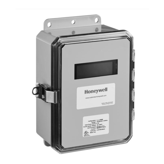
- Page 1 E-Mon Class 3400 Meter ADVANCED KWH/DEMAND METER WITH COMMUNICATIONS INSTALLATION INSTRUCTIONS 62-0398-02...
- Page 2 Before installing your new Honeywell E-Mon product, please read the information on the following pages carefully. We believe that you will find the Honeywell E-Mon meters easy to install and to use for monitoring and evaluating your electrical usage.
-
Page 3: Table Of Contents
RS-232 Communications Section 6.9 Modem Wiring Section 6.10 Modbus RTU Wiring Section 6.11 BACnet Wiring Section 6.12 Connecting E-Mon Class 3400 Meters to USB Key using RS485 Section 6.13 Ethernet Communications Section 7.0 Multiple-Load Monitoring Section 8.0 Preventative/Scheduled Maintenance Section 9.0 Lithium Battery Replacement Section 10.0... -
Page 4: Introduction
Verify the input voltage rating and configuration on the unit panel label to ensure that it is suitable for the intended electrical service. 3400 meters labeled for 120/ 208V service MUST NOT be installed on service feeds of 277/480 volts or 347/ 600 and vice versa. -
Page 5: Internal Electronic Assemblies
WARNING Use of this instrument, the Honeywell E-Mon Class 3400, in a manner inconsistent with this manual or not specified by the manufacturer in writing, can cause permanent damage to the unit and/or serious injury to the operator. -
Page 6: Main Power Board
E-MON CLASS 3400 METER 2.1 Main Power Board Connections to this board include the MAIN Power Input and current sensors.The MAIN Power Input terminals are positions one through four on the four position screw terminal block, TB1. These terminals are covered with a protective shield for safety purposes. -
Page 7: Display Board
The display board’s LCD readout indicates the metered values as well as errors associated with the E-Mon Class 3400 Meters, such as phase loss or sensor error conditions. -
Page 8: Meter Technical Specifications
A-BB-CCC-DDDD-E-FF-G-HHH, where: A = Brand: E for Honeywell E-Mon BB = designates Class: 3200 (32), 3400 (34), or 5000 (50) meter CCC = input voltage: (208, 480, 600, 120 volt for high voltage applications only) DDDD = current sensor rating: (100, 200, 400, 800, 1600, 3200, 25HV) - Page 9 E-MON CLASS 3400 METER 3.0 METER TECHNICAL SPECIFICATIONS (CONTINUED) Input Voltage 3-wire (Delta) Or 4-wire (Wye) Configuration Mains Voltage Up To 600 VAC RMS Available Input Input Power 6 VA Maximum Rating Current Sensor Up To 3200 Amps RMS AC Available...
- Page 10 E-MON CLASS 3400 METER 3.0 METER TECHNICAL SPECIFICATIONS (CONTINUED) RS-485 Serial Cable: UL-listed stranded Communications conductors, 22-26 AWG. Input/Output Voltage: Ground-isolated +/-5.4VDC Cable Connector: Screw terminal termination Circuit Input Isolation: 5.3kVAC Max Cable Distance: 4000 feet Max Network Nodes: 64 cabling nodes (including...
-
Page 11: Safety Label Definitions And Information
E-MON CLASS 3400 METER 4.0 SAFETY LABEL DEFINITIONS AND INFORMATION The E-Mon Class 3400 Meter may contain one or more of the following labels. Operator(s) should familiarize themselves with the meaning of each label to minimize risk. Notice This equipment has been tested and found to comply with the limits for a Class B digital device, pursuant to part 15 of the FCC Rules. -
Page 12: Precautionary/Safety Information
WARNING Failure to ground the enclosure creates a possible shock hazard. Do not operate the E-Mon Class 3400 Meter without a protective earth wire attached securely to the PE terminal screw. After installing protective earth wiring, secure the screw tightly (7 N-m torque.) WARNING NEVER open front panel of unit while unit has MAINS power applied. -
Page 13: Mounting The Class 3400 Meter
ESD protection. Prior to performing any unit wiring, be sure to discharge any static on your person. 2. Installing the E-Mon Class 3400 Meter protective earth ground: Connect an earth ground wire to the E-Mon Class 3400 Meter protective earth ground lug with a torque of 7 N-m. 62-0398—02... - Page 14 3. Wire Entry: E-Mon Class 3400 Meters are supplied with two 3/4” conduit K.O.s on the bottom of the 4X enclosure for all wiring. The Type1 enclosures are supplied with three 3/4” conduit K.O.s.
- Page 15 E-MON CLASS 3400 METER c. External Switch Mechanism/In-Line Fuse Installation To ensure a safe installation, the E-Mon Class 3400 Meter requires an external switch mechanism, such as a circuit breaker, be installed on the meter’s MAINS input wiring. The switch mechanism must be installed in close proximity to the meter and easily reachable for the operator.
-
Page 16: Phasing Of Line Voltage
E-MON CLASS 3400 METER 6.2 Main Power Board Connections (continued) Verify the voltage readings on Screen 5 using an AC voltmeter. Typical readings shown below are measured phase to neutral for 4 wire and phase to phase for 3 wire. Readings should be +/- 10% of nominal. -
Page 17: Current Sensor Installation & Wiring
9&10. Factory installed jumper should not be removed. The E-Mon Class 3400 Meter can be used with two types of 0-2V current sensors. 1. Split-core current sensor. This sensor opens so that it can be attached around the circuit being monitored without interrupting power. - Page 18 6.4.2 Current Sensor Wiring Once the current sensors are installed onto their appropriate phase conductors, you can begin terminating the current sensors onto the E-Mon Class 3400 Meter main board. The current sensors can be extended up to 500 feet for remote monitoring applications.
- Page 19 E-MON CLASS 3400 METER twice per second if there is a problem.If the monitored circuit is under load the LOAD LED will actively blink. A heavy load will cause the LED to blink faster than a light load. Very light loads will result in an extended blink time.
-
Page 20: Main Power & Current Sensor Wiring Diagram
E-MON CLASS 3400 METER 6.5 Main Power & Current Sensor Wiring Diagram LINE VOLTAGE CURRENT SENSORS 3-PHASE INSTALLATION DIAGRAM NOTES: LINE VOLTAGE CONNECTIONS: #14-22 AWG SENSOR CONNECTIONS: W = WHITE LEAD B = BLACK LEAD NEUTRAL NOT USED IN DELTA SYSTEM. -
Page 21: Line Voltage/Current Sensor Diagnostics
E-MON CLASS 3400 METER 6.6 Line Voltage/Current Sensor Diagnostics Following is a list of diagnostic messages that may appear on the meter display. DIAGNOSTIC MESSAGES SHOULD NOT BE ON CONTINUOUSLY WHEN THE METER IS INSTALLED PROPERLY AND IS IN WORKING ORDER. - Page 22 E-MON CLASS 3400 METER 6.6.2 Current Sensor Diagnostics The load current must be at least 1% of the meter’s rated load in order to use the diagnostic function. Current sensor diagnostics can detect: 1. Reversed current sensors 2. Incorrect phase correspondence 3.
-
Page 23: Rs-485 Wiring
RS-485 communication allows a computer or modem to communicate with one or more E-Mon Class 3400 Meters. You can connect as many as 52 meters along a 4000 foot RS-485 cable run. Class 3400 Smart meters are available with your choice of communication options: Honeywell E-Mon Energy (EZ7) standard, Modbus, BACnet. -
Page 24: Rs-232 Communications
6.8.1 Hard wired System using the RS-232 Communication Key The RS-232 communications key allows you to connect Class 3400 meters to a personal computer that has the Honeywell E-Mon Energy™ software installed. The computer communicates with the meters through the RS-232 key. - Page 25 LED (RS232 READY) will turn on. This indicator will light up as soon as the Honeywell E-Mon Energy software is booted up and the correct COM port is set up via the settings provided in the software’s Locations menu.
- Page 26 RS-232 key. Connect the other end of this cable to the meter via the RS- 485 port, at the bottom right of the Class 3400 meter main power board. “DATA Link” supplied with each RS-232 key should be utilized to connect key to meters.
-
Page 27: Modem Wiring
6.9.1 Built-In Modem (RS-232 KEY RM) The RS-232 key with built-in modem connects the entire RS-485 network of E- Mon Class 3400 Meters to a telephone line. ** Refer to Section 6.7 for RS-485 network connections. On the back panel of the RS-232 key/modem, the left jack (RS232) is not used in most cases since there is no local host computer. - Page 28 4 on the circuit board. There are four (4) selections: 9600 (factory default), 19200, 38400, and 76800. 1. Select 9600 when using the Class 3400 meter with a modem. 2. The baud rate on the meter must always match the baud rate selected in the Honeywell E-Mon Energy software;...
- Page 29 E-MON CLASS 3400 METER BAUD RATE 9600 19200 38400 OFF OFF 78600 M33277 Fig. 14. Baud Rate Selection. 6. Using other than 9600 BAUD will reduce the maximum cable length allowed for communication. 62-0398—02...
-
Page 30: Modbus Rtu Wiring
E-MON CLASS 3400 METER 6.10 Modbus RTU Wiring The E-Mon Class 3400 Modbus meter communicates with building automation equipment over a 2-wire (3-conductor) RS-485 network using Modbus RTU protocol. The meters are networked in a daisy-chain configuration (Section 6.7) with BELDEN 1120A cable or equivalent. The cable rating of 600V allows the RS- 485 network to be connected to 480-volt meters. -
Page 31: Bacnet Wiring
PC. UP TO 52, CLASS 3200 METERS, ON RS485 CABLING USB KEY PC WITH USB UP TO 4000 FEET TOTAL RS485 CABLE M34372 Fig. 16. Connecting Class 3400 Meters to the USB Key using RS485. 62-0398—02... -
Page 32: Ethernet Communications
RS-485 output. E- Mon Class 3400 Meters can be tied into a local Ethernet network individually. Multiple RS-485 meters to Ethernet requires optional “EKME” device. Each device that is connected directly to the ethernet network requires a unique IP address. -
Page 33: Multiple-Load Monitoring
E-MON CLASS 3400 METER 7.0 MULTIPLE-LOAD MONITORING The Honeywell E-Mon Class 3400 Meter provides extreme flexibility by allowing additional sets of current sensors to be used in parallel so multiple load locations can be monitored by one meter. This feature allows a totalized display readout from two or more load circuits. - Page 34 E-MON CLASS 3400 METER NOTE: One set of current sensors equates to three sensors, one per phase. The multiplier only applies when extra sets of current sensors are installed on one meter. If you are using only one set of three current sensors, the mul- tiplier is not required.
-
Page 35: Preventative/Scheduled Maintenance
No cleaning or decontamination procedures are required for this instrument. 9.0 LITHIUM BATTERY REPLACEMENT The E-Mon Class 3400 Meter has a Lithium Battery Cell, which is used to retain the contents of SRAM and the RTC during power outages. The battery has a life expectancy of greater than 5 years. - Page 36 E-MON CLASS 3400 METER – BATTERY M33278 Fig. 21. Lithium Battery Cell. Use the following procedure to replace the battery cell 1. Disconnect power from the meter at the unit external circuit breaker. 2. Remove the battery from its holder and place on a non-conductive surface.
-
Page 37: E-Mon Class 3400 Meter Operating Modes
E-MON CLASS 3400 METER 10.0 E-MON CLASS 3400 METER OPERATING MODES The Honeywell E-Mon Class 3400 Meter is used to monitor electric power usage of individual loads after the utility meter and store kW and kVAR data for automatic meter reading. - Page 38 E-MON CLASS 3400 METER 10.2 Normal Mode Display Screens The E-Mon Class 3400 Meter features seven Normal Mode Display Screens for monitoring the meter. Each screen is displayed for 5 second intervals, before scrolling onto the next screen. You can “lock” the scrolling display on any one of the seven screens. This will be explained in detail on following pages.
- Page 39 E-MON CLASS 3400 METER SELECT DOWN MENU M33320 Fig. 23. Push Buttons. 10.2 How to Program the Display Screens The display information can be programed using four push buttons switches. The push buttons (DOWN, UP, SELECT, MENU) are located at the top of the display board on the inside front door of the meter.
- Page 40 E-MON CLASS 3400 METER 10.2.1 Load Control Display Screen The E-Mon Class 3400 Meter Load Control Relay is an option (the card includes load control, pulse input [2], and pulse output [2] - for Load Control, order option “-X-”Expanded Feature Package); it is used to activate alarming or load control.
- Page 41 E-MON CLASS 3400 METER 3. Press the SELECT button. The Load Control Screen will appear. LOAD: 0.0 KW LIMIT:5.5 KW VAR: +3.5 KW R/H:5/20 4. Use UP or DOWN button to make changes, press the SELECT button to advance to the next setting. Repeat this step until all the settings have been updated.
- Page 42 E-MON CLASS 3400 METER 10.2.2 Date & Time Display Screen To change the date and time, complete the following steps: 1. Press the MENU button. 2. The following screen will appear: —> LOAD CONTROL DATE & TIME DEVICE ID IP SETTINGS 3.
- Page 43 E-MON CLASS 3400 METER 10.2.2 Device I.D. Display Screen To change Device I.D., complete the following steps: 1. Press the MENU button. 2. The following screen will appear: —> LOAD CONTROL DATE & TIME DEVICE ID IP SETTINGS 3. Use UP or DOWN button until the arrow is on the Device ID line.
- Page 44 E-MON CLASS 3400 METER 10.2.3 IP Setting Display Screen To Change the IP settings, complete the following steps: 1. Press the MENU button. 2. The following screen will appear: —> LOAD CONTROL DATE & TIME DEVICE ID IP SETTINGS 3. Use UP or DOWN button until the arrow is on the IP Setting line.
- Page 45 The board contains two pulse inputs for connection to external metering devices which have a dry-contact type of output pulse. The maximum frequency of pulses accepted by the E-Mon Class 3400 Meter is 10Hz. Pulse Output The board contains two pulse outputs for use by Building Automation Systems, etc.
- Page 46 E-MON CLASS 3400 METER 11.1 Expansion Feature Package Board Connections (Optional) – – – – INP1 INP2 OUT1 OUT2 IO - Terminals COM2 COM1 M33321 Relay - Terminals 62-0398—02...
-
Page 47: Pulse Type And Valve
E-MON CLASS 3400 METER 11.2 Pulse Type and Value The pulse outputs provided by the E-Mon Class 3400 Meter are watt-hours and var-hours. Output 1 is the watt-hour pulse and Output 2 is the var-hour pulse. The pulse value is dependent on the amperage size of the meter. See the chart below for the values also true for expansion board pulse output. -
Page 48: Frequently Asked Questions
When you read the meter, the final reading must be multiplied by the number of feed wires for each phase. Q. I have two subpanels I would like to monitor with one E-Mon Class 3400 Meter. These subpanels are fed by different transformers in the building. Can I parallel sensors and monitor both panels with one meter? A. - Page 49 Q. I’ve gone through the troubleshooting guides and I still can’t get my E-Mon Class 3400 Meter to work. What should I do? A. Before removing the unit, contact Honeywell E-Mon’s technical services department at (888) 516-9347. Honeywell E-Mon’s technical department will assist you in detailed troubleshooting of the meter installation and assist you in getting the unit running without having to remove and/or return it.
-
Page 50: Protocol Descriptions
E-MON CLASS 3400 METER 13.0 PROTOCOL DESCRIPTIONS ModBus Customer Point Map: CL3400 Address Registers Format Description Units 3400 Integer Energy delivered Wh Pulse 40001 Integer Energy received Wh Pulse 40003 Integer Reactive energy delivered VARh Pulse R/W 40005 Integer Reactive energy received... - Page 51 0000 0000 0000 0000 0000 0000 0000 0000. Remove Jumper J6 after changes have been made. 2. External inputs are standard on Class 5000 meters and optional on Class 3400 meters (Part of Expanded Feature Package).
- Page 52 E-MON CLASS 3400 METER BACnet Object Descriptors: CL3400 Instance BACnet BACnet Object Description Units Property 3400 Analog Energy delivered Present Input Value Analog Energy received Present Input Value Analog Reactive energy delivered kVARh Present Input Value Analog Reactive energy received...
- Page 53 E-MON CLASS 3400 METER BACnet Object Descriptors: CL3400 Instance BACnet BACnet Object Description Units Property 3400 Analog Reactive power phase C kVAR Present Input Value Analog Apparent power phase A Present Input Value Analog Apparent power phase B Present Input...
- Page 54 Remove J6 when changes have been completed. 2.External inputs are standard on Class 5000 meters and optional on Class 3400 meters (Part of Expanded Feature Package). To clear external inputs, select reset kW/kWh on the display menu of the meter. This function will also reset kW/ kVARh.
- Page 55 E-MON CLASS 3400 METER BACnet Device ID Device Max APDU length supported BACnet Device ID Device Segmentation supported BACnet Device ID Device Local time BACnet Device ID Device Local date BACnet Device ID Device APDU time out BACnet Device ID...
-
Page 56: High Voltage Metering
CT secondary is installed as a continuous “loop”, with a single conductor connected to both secondary terminals. To convert the 0~5 amp signal to a 0~ 2 volt signal, Honeywell E-Mon’s Current Sensors are installed on the CT secondary conductor. A set of 25 amp sensors is used in this application. - Page 57 E-MON CLASS 3400 METER PASS PASS PASS PASS PASS M34227 Fig. 25. High Voltage CTs. HIGH VOLTAGE CURRENT SENSORS WITH SECONDARY AT 5 AMP VOLT INPUT CURRENT INPUT A B C N W B W B W B 120 VAC...
- Page 58 The high voltage CT secondary is installed as a continuous “loop”, with a single lead connected to both secondary terminals. Honeywell E-Mon meters accept a 0~2 volt signal from their Current Sensors. To convert the 0~5 amp signal, the Current Sensors are installed on the CT secondary lead.
- Page 59 E-MON CLASS 3400 METER Number of Secondary Lead Passes Through Sensor]. The Honeywell E-Mon 25 amp HV kWh meter with 5 wraps of the high voltage CT secondary will have its multiplier calculated by the formula shown below. EXAMPLE: CT = 400:5 = 80:1 (CTr = 80)
- Page 60 2. Honeywell must be notified of the defect within ninety (90) days after the defect becomes apparent or known. 3. Buyer’s remedies shall be limited to repair or replacement of the product or component which failed to conform to Honeywell’s express warranty set...
- Page 61 Route the appropriate cabling to and through the respective enclosure opening. 2. Installing the Class 3400/5000 protective earth ground: Connect an earth ground wire to the Class 5000 protective earth ground lug with a torque of 7 N-m.
- Page 62 E-MON CLASS 3400 METER Chapter 6.7 RS-485 Wiring Addendum 1. Open the supplied Ferrite Bead. 2. Loop the RS-485 network cable around itself one time, creating a loop large enough to fit over the length of the Ferrite Bead. Be sure to make the loop so that the Ferrite Bead is no more than 2”...
- Page 63 E-MON CLASS 3400 METER 62-0398—02...
- Page 64 E-MON CLASS 3400 METER Home and Building Technologies In the U.S.: Honeywell 715 Peachtree Street NE ® U.S. Registered Trademark Atlanta, GA 30308 © 2018 Honeywell International Inc. 62-0398—02 M.S. Rev. 05-18 customer.honeywell.com Printed in United States...