
Related Manuals for Electrolux EDS

Summary of Contents for Electrolux EDS
- Page 1 Installation manual EDS, Efficient Dosing System 438 9196-50/EN Original instructions 2016.04.13...
-
Page 3: Table Of Contents
Language settings ........................19 Time and date settings ......................19 Priming the pumps ........................19 Calibrating the pumps ......................20 Basic settings in the EDS controller ...................23 Wash program set up .......................25 Download reports to a USB stick ....................27 Electrolux wash program allocation ...................28 3.10 Selection of operation mode .....................29... -
Page 5: Introduction
The EDS controller receives a signal from the washer extractor at predetermined times in the wash program. Once a signal is received the EDS injects specific product(s) at that time in proportion to the weight of the linen as de- termined via the automatic saving system. -
Page 6: Installation
• Do not locate the pump-stand under plumbing fittings that could leak. • Ensure that the installer has enough room to carry and lift the units when installing the EDS system. • Do not pick up unit by supply cord. -
Page 7: Requirements
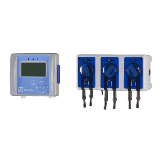
• The EDS controller must be mounted securely to a wall or on the washer extractor. The EDS controller can be mounted to a horizontal or vertical surface such as a wall or on the side panel on a washer extractor. - Page 8 Installation manual Connect the cable from the pump-stand to the J1 port on the EDS controller. fig.8055A Connect the hoses to the pump-stand. Connect the hose from the liquid detergent to the left on each pump. The hose from the pump to the washer extractor is connected to the right on each pump.
-
Page 9: Installation Of Flush Manifold (Option)
Installation manual The washer extractor is prepared for connection of external dosing systems or water re-use systems etc. The connections are closed at delivery. Open the connections (A) that shall be used by drilling a ⌀ 6 mm hole where the hoses shall be connected. -
Page 10: Installation Of The Eds Controller
The EDS controller can be mounted on a wall or on the side panel on a washer extractor. Connect the cables on the back of the EDS controller. Mount the mounting plate on its location and mount the EDS controller on the mounting plate. -
Page 11: Installation On Compass Control And Compass Pro
Remove one of the covers to the holes on the back of the machine. The location is different on different models. The cable from the J2 port on the EDS controller shall then be run through the hole (A) and connected to the RS232 port on the I/O module. - Page 12 Remove one of the covers to the holes on the back of the machine. The location is different on different models. The cable from the J2 port on the EDS controller shall then be run through the hole (A) and connected to the RS232 port on the I/O module.
- Page 13 Connect the cable from the J2 port on the EDS controller to the RS232 port on the I/O module. The connection is in the bottom of the I/O module. It might be necessary to temporarily demount the I/O module to be able to connect.
- Page 14 Remove one of the covers to the holes on the back of the machine. The location is different on different models. The cable from the J2 port on the EDS controller shall then be run through the hole (A) and connected to the RS232 port on the CPU module at the front of the machine.
- Page 15 Demount the cover. Connect the cable from the J2 port on the EDS controller to the RS232 port on the CPU module. fig.W01147 Strap the cable at suitable positions. The cable must not be in contact with the drum.
-
Page 16: Installation On Clarus Control
Disconnect the power to the machine. The cable from the RJ11 port on the EDS controller shall be run through a hole at the back of the machine (A) and connected to the X10 connection on the CPU card A1. - Page 17 Installation manual The cable from the RJ11 port on the EDS controller shall be run through a hole at the back of the machine (A) and connected to the X10 connection on the CPU card A1. Insert the cable and mount with the counter nut and cable gland according to the figure.
-
Page 18: Dual Controller
When more pumps are needed it is possible to connect two EDS controllers to the same washer extractor. This makes it possible to have up to eleven pumps. Connect one of the EDS controllers to the RS232 port on the I/O module and the other EDS controller to the RS232 port on the CPU module. -
Page 19: Programming
If changing from one of the pre-set languages, the language-enabled USB stick must be connected before powering up the EDS controller. Insert the language enabled USB stick. Power up the EDS controller, select language and press Enter to save. 3.3 Time and date settings When the language has been set the “Date and time menu”... -
Page 20: Calibrating The Pumps
Installation manual A password is needed to continue. The default password is set to 01234. When the password is set you will enter the INSTALLER MENU. Activate the INSTALLER SERVICE menu. INSTALLER MENU INSTALLER SERVICE INITIAL SYSTEM SETUP PROGRAM FORMULAS DATA TRANSFER SET UNITS OF MEASURE Activate the SERVICE PUMPS menu. - Page 21 Installation manual A password is needed to continue. The default password is set to 01234. When the password is set you will enter the INSTALLER MENU. Activate the INSTALLER SERVICE menu. INSTALLER MENU INSTALLER SERVICE INITIAL SYSTEM SETUP PROGRAM FORMULAS DATA TRANSFER SET UNITS OF MEASURE Activate the SERVICE PUMPS menu.
- Page 22 Installation manual Press enter to stop at exactly 250 ml. Repeat the calibration for all of the pumps. fig.8052 Note! If the pumps are not calibrated they will not run even if there is an amount programmed. Note! If the calibration time for each pump is longer than 52 seconds for 250 ml (50 seconds for 8 oz.) this indicates that the pump outlet is 25% below rated flow rate.
-
Page 23: Basic Settings In The Eds Controller
Installation manual 3.6 Basic settings in the EDS controller In order for the EDS system to work the following basic settings must be made in the EDS controller. Enter the MAIN MENU and activate the INSTALLER MENU. MAIN MENU EMERGENCY PUMP STOP... - Page 24 For a Compass Control/Compass Pro machine the EDS controller’s address is pre-set to 000. For a Clarus Control machine the EDS controller’s address is pre-set to 001. Make sure the washer extractor’s address is also set to 0 or change the EDS controller’s address to match the ad- dress in the washer extractor.
-
Page 25: Wash Program Set Up
• For Formula Editor Program the software is downloaded to a Windows based PC from the manufacturers web page. The formula/wash program is when ready saved to a .SUP-file that is loaded to the EDS controller via a USB stick. - Page 26 Installation manual Insert the USB stick with the downloaded wash programs in the EDS controller. Activate the READ SETUP menu. DATA TRANSFER WRITE REPORTS READ SETUP WRITE SETUP UPDATE FIRMWARE WRITE ACTIVITY LOG Activate the setup file from the list. Before uploading there will be a warning message on the display. Press Enter to upload the selected setup file.
-
Page 27: Download Reports To A Usb Stick
Activate the DATA TRANSFER menu. INSTALLER MENU INSTALLER SERVICE INITIAL SYSTEM SETUP PROGRAM FORMULAS DATA TRANSFER SET UNITS OF MEASURE Insert the USB stick in the EDS controller. Activate the WRITE REPORTS menu. DATA TRANSFER WRITE REPORTS READ SETUP WRITE SETUP UPDATE FIRMWARE WRITE ACTIVITY LOG Set the current date for the report and press Enter. -
Page 28: Electrolux Wash Program Allocation
Before resetting the data log there will be a warning message on the display. Press Enter. Set the current date and press Enter to reset the data log. Note! Resetting the data log will not affect the main program settings. 3.9 Electrolux wash program allocation Enter the MAIN MENU and activate the INSTALLER MENU. MAIN MENU EMERGENCY PUMP STOP... -
Page 29: Selection Of Operation Mode
F01 PROGRAM LIST E1 016 Assign the selected formula/wash program to the machine’s Electrolux wash program. This formula/wash program can be assigned to 6 different Electrolux wash programs. E1 PROGRAM 3.10 Selection of operation mode There are two different operation modes, Standard mapping and Euro mapping. - Page 30 Installation manual A password is needed to continue. The default password is set to 01234. When the password is set you will enter the INSTALLER MENU. Activate the INITIAL SYSTEM SETUP menu. INSTALLER MENU INSTALLER SERVICE INITIAL SYSTEM SETUP PROGRAM FORMULAS DATA TRANSFER SET UNITS OF MEASURE Activate the SET PUMP MAPS menu.
- Page 31 Installation manual Euro mapping Euro mapping shall only be used on machines with quick selection buttons or when rapid advance is used. In Euro mapping there are 6 available washer signals/programs: • Pre-wash • Main wash • Final rinse • Spare 1 •...
-
Page 32: Test Run
Installation manual 4 Test run Test run the system when the installation completed. Select a wash program, start the washer extractor and observe a test load to ensure that all products dispense only when they are supposed to dispense. 5 Technical specification •... -
Page 33: Trouble Shooting And Service
Flush manifold When Flush manifold is used, water flow is sensed whenever the EDS controller calls for water flush. If no water flow is sensed, or water flow falls below 2.5 l/min, all pumps will shut down. This provides a safety interlock in the event of low water flow or other water flush system failures. - Page 34 Symptom Observation Cause Solution 1. No power to unit 1. No power at source 1. Reset the power to the EDS EDS controller display is not working controller 2. No power to PI PCB 2. Tripped or defective circuit 2. Reset or replace circuit...
- Page 35 Installation manual Pump-stand disassembly Disconnect the power to the unit. Before disconnecting, make note of all connections. Remove the front of each pump by removing two captive thumbscrews per pump front. Remove the pump tubes. Re- move the pump spinners. Remove the cabinet of the pump-stand by removing four Phillips head screws, one at each corner and two at the bot- tom of the pump tube.
- Page 36 Installation manual Power wiring Incoming power wiring from the Wiring Harness Plate Assembly connects to the Pump Interface Printed Circuit Board power terminal block (Found on Item 1, Replacement Parts List). • 115 V The live wire goes to terminal 1. The neutral wire goes to terminal 4. Black jumper between terminal 1 and terminal 2.
- Page 40 Electrolux Laundry Systems Sweden AB 341 80 Ljungby, Sweden www.electrolux.com/professional Share more of our thinking at www.electrolux.com...