Quick Links
Installation Instructions
Important Safety Information
See the Important Safety and Product Information guide in the
product box for product warnings and other important
information.
When connecting the power cable, do not remove the in-line
fuse holder. To prevent the possibility of injury or product
damage caused by fire or overheating, the appropriate fuse
must be in place as indicated in the product specifications. In
addition, connecting the power cable without the appropriate
fuse in place voids the product warranty.
Always wear safety goggles, ear protection, and a dust mask
when drilling, cutting, or sanding.
When drilling or cutting, always check what is on the opposite
side of the surface.
To obtain the best performance and to avoid damage to your
boat, install the device according to these instructions.
Read all installation instructions before proceeding with the
installation. If you experience difficulty during the installation,
contact your Yamaha
dealer.
®
Tools Needed
• Appropriate pigtail bus wire for engine network connection
• Drill and drill bits
1
◦ 3.2 mm (
/
in.) drill bit, if using wood screws
8
9
◦ 3.6 mm (
/
in.) drill bit, if using the nut plates (optional
64
accessory)
9
◦ 7.2 mm (
/
in.) drill bit, if using the nut plates (optional
32
accessory)
• Mounting hardware
◦ 4 Wood screws (included)
◦ 4 M4 machine screws if using the nut plates (included with
nut plate accessory)
◦ 4 M3 machine screws if using the nut plates (included with
nut plate accessory)
• #2 Phillips screwdriver
• Jigsaw or rotary tool
• File and sandpaper
• Marine sealant (recommended)
Mounting Considerations
This device should be mounted in a location that is not exposed
to extreme temperatures or conditions. The temperature range
for this device is listed in the product specifications. Extended
exposure to temperatures exceeding the specified temperature
range, in storage or operating conditions, may cause device
March 2018
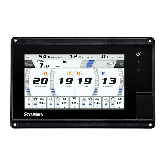
CL7 DISPLAY
WARNING
NOTICE
NOTICE
failure. Extreme-temperature-induced damage and related
consequences are not covered by the warranty.
When selecting a mounting location, you should observe these
considerations.
• The location should provide optimal viewing as you operate
your boat.
• The location should allow for easy access to all device
interfaces, such as the keypad, touchscreen, and card
reader, if applicable.
• The location must be strong enough to support the weight of
the device and protect it from excessive vibration or shock.
• To avoid interference with a magnetic compass, the device
should not be installed closer to a compass than the
compass-safe distance value listed in the product
specifications.
• The location must allow room for the routing and connection
of all cables.
• The location must not be a flat, horizontal surface. The
location should be in a vertical angle.
The location and viewing angle should be tested before you
install the device. High viewing angles from above and below
the display may result in a poor image.
Mounting the Device
Be careful when cutting the hole to flush mount the device.
There is only a small amount of clearance between the case and
the mounting holes, and cutting the hole too large could
compromise the stability of the device after it is mounted.
There are different options for hardware based on the mounting
surface material. You may need additional hardware depending
on the mounting option selected.
• You can drill pilot holes and use the included wood screws.
• You can drill holes and use nut plates and machine screws
(optional accessory). The nut plates can add stability to a
thinner surface.
1
Trim the template and make sure it fits in the location where
you want to mount the device.
2
Secure the template to the selected location.
3
1
Using a 13 mm (
/
in.) drill bit, drill one or more of the holes
2
inside the corners of the solid line on the template to prepare
the mounting surface for cutting.
4
Using a jigsaw or a rotary tool, cut the mounting surface
along the inside line on the template.
5
Place the device in the cutout to test the fit.
6
If necessary, use a file and sandpaper to refine the size of
the cutout.
7
After the device fits correctly in the cutout, ensure the
mounting holes on the device line up with the larger holes in
the corners of the template.
8
If the mounting holes on the device do not line up, mark the
new hole locations.
9
Based on your mounting surface, drill or punch and tap the
larger holes:
1
• Drill 3.2 mm (
/
in.) pilot holes for wood screws, and skip
8
to step 17.
9
• Drill 7.2 mm (
/
in.) holes for the nut plate and machine
32
screws, and continue to the next step.
10
If using the nut plates (optional accessory), starting in one
corner of the template, place a nut plate
hole
drilled in step 9.
NOTICE
over the larger
190-02076-02_0B
6YD-2819K-E0

Related Manuals for Yamaha CL7


Summary of Contents for Yamaha CL7
-
Page 1: Installation Instructions
When selecting a mounting location, you should observe these considerations. • The location should provide optimal viewing as you operate CL7 DISPLAY your boat. • The location should allow for easy access to all device interfaces, such as the keypad, touchscreen, and card Installation Instructions reader, if applicable. - Page 2 • The cables may be packaged without the locking rings installed. The cables should be routed before the locking rings are installed. • After installing a locking ring on a cable, you should make sure the ring is securely connected and the o-ring is in place so the power or data connection remains secure.
- Page 3 • The power cable from this device and the NMEA 0183 device must be connected to a common power ground. Item Description CL7 display N0183+, white GPS antenna N0183-, blue Ignition or in-line switch NMEA 0183 device...
-
Page 4: Specifications
BNC to RCA adapter to connect a composite-video source with RCA connectors to the CVBS IN port. © 2017–2018 YAMAHA Motor Co., LTD or its • Video is shared across the Garmin Marine Network, but it is subsidiaries not shared across the NMEA 2000 network.