Quick Links
ACU Wireless Analog Converter Unit – Quick Installation Guide
For Online Support visit: http://www.security.honeywell.com/hsc/resources/MyWebTech/
General Information
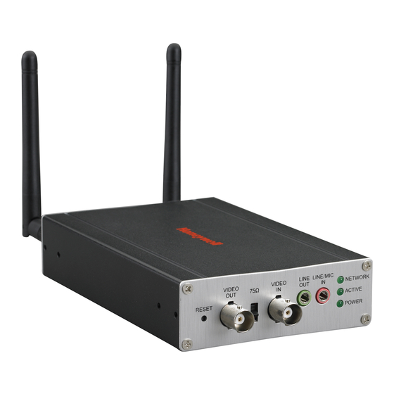
This guide provides information on installing and setting up Honeywell's ACU Wireless
Analog Converter Unit (referred to as the ACU). The ACU allows any camera that outputs
NTSC video to be used with Honeywell's Total Connect Video services.
Some major features of Honeywell's ACU Wireless Analog Converter Unit are:
Wired or Wireless communications. Wireless communications utilize the 802.11n
protocol with WPS security. WPS (Wi-Fi Protected Setup) is a standard for easy setup of
a secure wireless network.
Has a video pass-through connection for a direct NTSC video feed to a local monitor.
Status LEDs, and 10/100 Mbps Ethernet port connectivity.
IMPORTANT: This device is for indoor use only. DO NOT mount this ACU within one foot
(0.3m) of any wireless device.
To utilize the ACU, you must have:
An AlarmNet account for a GSM or Internet communicator, or a "Video Services Only"
account.
Total Connect account. (If an account does not exist, the dealer should use the
AlarmNet Direct website to set up a Total Connect account for the customer.)
Internet access with a router capable of DHCP hosting. For wireless use, the router
must also support one button WPS data encryption. If this is not available, order the
Honeywell WAP-PLUS Wireless Access Point for connection to your router.
Component Identification
75
LINE
VIDEO
VIDEO
OUT
OFF
OUT
IN
RESET
RESET and WPS switch – Used to reset the
ACU to factory defaults and is also used to initiate
WPS for wireless security.
Reset – Ensure the POWER LED is on and not
blinking. Then use a paper clip to depress for
12-seconds. After the unit reboots, the POWER
LED will blink 3 times to confirm the reset has
completed.
WPS – Refer to the topic on Configuring
Wireless Security.
VIDEO OUT – Pass through BNC connector.
Enables the NTSC video from the camera to be
fed to a local monitor. When a local monitor is
used, ensure the adjacent 75Ω OFF switch is set
to the UP position.
VIDEO IN – Attach the NTSC output from your
video camera here.
Planning the camera installation
The installation can be as simple as installing one ACU and NTSC camera, or multiple ACUs to support up
to six cameras per Total Connect account. Large installations may include a mix of wireless, and wired ACUs.
The installer should work closely with the customer to achieve a satisfactory installation.
Layout Considerations:
Depending on layout and distances, one or more WAP-PLUS units may be needed.
Wireless distance may be reduced by thick walls, wire lath, and large metal objects. For installations
where wireless connectivity is poor, see if the WAP-PLUS has the newer WAP-ANT5dB antennas.
They are approximately 6 inches (15cm) long. If not, they can be ordered to retrofit the WAP-PLUS.
When setting up a wireless configuration in very large buildings or buildings with dense walls, wireless
communications may be marginal. It is best to first configure the system's wireless security in the
same room (within 20 feet, 6m). Then upon successful configuration, place each camera in the
desired location, and verify in Total Connect that everything works.
For installations where multiple WAP-PLUS units are used, label the units to indicate which IP cameras
are linked to which WAP-PLUS.
Each IP camera or ACU (Analog Converter Unit) will communicate through its associated
WAP-PLUS.
Each WAP-PLUS must be spaced at least 4 feet (1.2m) from other wireless devices.
Ensure each device uses the correct power transformer. When needed, secure wires with cable ties.
Refer to the installation guides for the WAP-PLUS, ACU (Analog Converter Unit), and each IP camera
for detailed information about that product.
NETWORK
LINE/MIC
IN
ACTIVE
POWER
LINE OUT – (Not used.)
LINE / MIC IN – (Not used.)
NETWORK LED
Steady Green – The LAN is detected and active.
Blinking Green – Data is being transferred via
the LAN.
ACTIVE LED
Blinking Green – ACU camera is being viewed
via the internet.
Off – ACU camera is not being viewed via the
internet.
POWER LED
Blinking Green – Will blink during initial power
up condition, allow up to 2 minutes.
Steady Green – Power is on.
PACKAGE CONTENTS
ACU Wireless Analog Converter Unit
antenna connector – Orient the antennas vertically. Used for wireless connectivity
ETHERNET – For connection to any router (configured for DHCP), or Honeywell's
WAP-PLUS Wireless Access Point. Supports 10/100 Mbps.
(Using the Ethernet connector will disable the wireless communications.)
GPIO Connector – (Not used.)
POWER – Connection for the Power Transformer (12V/1A).
Wireless Range:
The wireless range and bandwidth (data rate) are dependent on the wireless
technology used; as determined by the 802.11b/g/n specifications. This deter-
mines the range and data transfer rate. For instance under ideal conditions,
802.11 g provides up to 125 ft. (38m) range, and 54Mbits/s data rate, and
802.11 n provides up to 230 ft. (70m) range, and 150Mbits/s data rate.
Other factors that reduce the range are thick walls, wire lath, large metal objects,
and the number of cameras sending data.
Because of the many variables, the best way to determine if the installation is
successful, is to test the finished installation by logging into the Total Connect
website and checking each camera.
Power Transformer
(6 ft., 1.8m)
Hardware Bag (includes)
Mounting brackets [2] with screws [4]
Antennas [2]
GPIO Connector
(Always use both antennas).

Related Manuals for Honeywell ACU


Summary of Contents for Honeywell ACU
- Page 1 Planning the camera installation The installation can be as simple as installing one ACU and NTSC camera, or multiple ACUs to support up Wireless Range: to six cameras per Total Connect account. Large installations may include a mix of wireless, and wired ACUs.
- Page 2 Transformer into an outlet. Ensure the ACU is powered up and fully booted (allow 2 2. If a local monitor is to be used, connect the VIDEO OUT on the ACU to the video input on the monitor. minutes for the boot process to complete).