Huawei BBU3900 Installation Manual
Hide thumbs
Also See for BBU3900:
- Hardware description (104 pages) ,
- Hardware maintenance manual (58 pages) ,
- Description (29 pages)

Related Manuals for Huawei BBU3900


Summary of Contents for Huawei BBU3900
- Page 1 BBU3900 Installation Guide Issue: 19 Date: 2011-01-20 HUAWEI TECHNOLOGIES Co., Ltd.
-
Page 2: Table Of Contents
Installing the BBU in the APM30H(Ver.B, +24V) …………………………… Installing the BBU in the OMB ………………… BBU Hardware Installation Checklist………… Powering On the BBU…………………………… Obtaining the ESN ……………………………… Appendix…………………………………………… Change History…………………………………… Copyright © Huawei Technologies Co., Ltd. 2011. All rights reserved. -
Page 3: Installation Tools
Installation Tools Measuring tape Phillips screwdriver (M3-M6) Flat-head screwdriver (M3-M6) Adjustable wrench Socket wrench Hammer drill Wire stripper ESD wrist strap Vacuum cleaner Torque wrench Marking pen Level Rubber Mallet RJ-45 crimping tool Multimeter Power cable crimping tool Cable cutter ESD gloves... -
Page 4: Installation Scenarios
Installation Scenarios The GTMU in this document is based on the first type of GTMU. In the APM30/APM30H(Ver.A) In the PS4890 In the 19-inch rack In the APM30H(Ver.B) In the TMC In the RRU3004 rack... - Page 5 Installation Scenarios In the TMC11H(Ver.B) In the APM30H Ver.B, +24V) On the wall In the OMB...
-
Page 6: Bbu Hardware
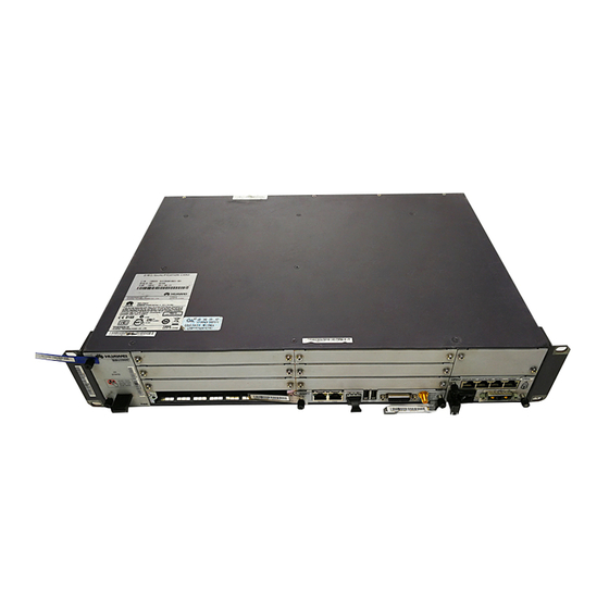
BBU Hardware 1. Exterior of the BBU 86 mm (2U) 2. Configuration Principles of the BBU Boards Board Mandatory/ Full Configuration Installation Remarks Optional Slot GTMU Mandatory S5 and S6 Can be installed only in S5 and S6. UPEU Mandatory S18 or S19 A single UPEU is preferentially configured in the S19 slot. -
Page 7: Installation Procedure
Installation Procedure When the equipment is unpacked, it must be powered on in seven days. The maximum duration of the power-off state of the equipment is 48 hours during maintenance. -
Page 8: Installing The Bbu In The Apm30
Installing the BBU in the APM30 Installing the BBU Case 1. Install the mounting ears at both sides of the BBU reversely. M6 bolt 2. Slide the BBU case into the cabinet. Installing the BBU Cables Cable connections of the BBU External power supply External monitoring device External alarm device... - Page 9 Installing the BBU in the APM30 Installing the BBU Cables 1. Install BBU power cable. Connect the OT terminal of the power cable to the LOAD3 terminal of the PDU, and then fix the 3V3 connector of the power cable to the PWR port on the BBU. LOAD3 NEG(-) RNT(+)
- Page 10 Installing the BBU in the APM30 Installing the BBU Cables 3. Install the E1/T1 surge protection transfer cable. Fix the DB25 connector of the E1/T1 surge protection transfer cable to the INSIDE port on the UELP and the DB26 connector to the E1/T1 port on the GTMU. 4.
- Page 11 Installing the BBU in the APM30 Installing the BBU Cables 5. Install the FE/GE surge protection transfer cable (FE/GE transmission mode). Connect one end of the FE/GE surge protection transfer cable to the FE0 port near the INSIDE label on the UFLP and the other end to the FE0 port on the GTMU.
- Page 12 Installing the BBU in the APM30 Installing the BBU Cables 8. Install the EMUA monitoring signal cable. (The EMUA is configured if there are external dry contacts or analog detection is required.) Cut off the RJ45 connector of the EMUA monitoring signal cable, and then connect the four exposed wires to the RX+, RX-, TX+, and TX- ports on the APMI.
- Page 13 Installing the BBU in the APM30 Installing the BBU Cables 9. Install the alarm cable. Connect one end of the alarm cable to the EXT-ALM port on the UPEU and the other end to the corresponding alarm device.
-
Page 14: Installing The Bbu In The Apm30H(Ver.a)
Installing the BBU in the APM30H(Ver.A) BBU Cable Connections The procedure for installing the BBU case in the APM30H is the same as that in the APM30. For details, see pages 7 to 12. The following figure shows the cable connections of the BBU. For details on how to install the monitoring signal cable between the HEUA and the BBU in the APM30H, see page 14. - Page 15 Installing the BBU in the APM30H(Ver.A) Installing the Monitoring Signal Cable Between the HEUA and the BBU HEUA COM IN MON1 UPEU on the...
-
Page 16: Installing The Bbu In The 19-Inch Rack
Installing the BBU in the 19-Inch Rack Space Requirements When the BBU3900 is installed in the 19-inch cabinet, no space is required on the left and right of the BBU3900. Installing the DCDU-03B Installing the BBU Case... - Page 17 Installing the BBU in the 19-Inch Rack Installing the BBU Cables Cable Installation Position One end is connected to... The other end is connected to... CPRI optical cable CPRI port on the GTMU CPRI port on the RRU External power BEG(-) and RTN(+) on the DCDU-03B External power equipment cable...
-
Page 18: Installing The Bbu In The Tmc
Installing the BBU in the TMC Installing the DCDU-03B Slide the DCDU-03B into the TMC. Then, tighten the four M6 screws. Installing the BBU Case Slide the BBU into the TMC. Then, tighten the four M6 screws. - Page 19 Installing the BBU in the TMC Installing the BBU Cables DCDU-03B input power cable For details on how to install the TMC alarm cable, see page 19. The DCDU-03B input power cable is connected to the external DC power supply system. For cable connections of the BBU, see page 7.
- Page 20 Installing the BBU in the TMC Installing the BBU Cables Procedure for installing the Door status TMC alarm cable: APMI panel sensor a. Fix the RJ45 connector at one end of the alarm cable to the EXT_ALM1 port on the BBU. b.
-
Page 21: Installing The Bbu In The Ps4890 Cabinet
Installing the BBU in the PS4890 Cabinet Installing the DCDU-03B 1. Slide the DCDU-03B into the 2. Install the DCDU-03B input power cable. PS4890 cabinet. Then, tighten the Connect one end of the power cable in blue to the four M6 screws. DC output terminal LOAD2(-) on the power subrack and the other end to the DC input terminal NEG(-) on the DCDU-03B . - Page 22 Installing the BBU in the PS4890 Cabinet Installing the BBU Cables Cable connections of the BBU Connect the BBU power cable to the DC output terminal LOAD6 of the DCDU-03B. CPRI optical cable BBU power cable E1/T1 cable Monitoring signal cable between the PMU BBU alarm cable and the BBU In addition to the BBU cables installed in the APM30, a monitoring signal cable between the PMU and the BBU needs to...
- Page 23 Installing the BBU in the PS4890 Cabinet Installing the BBU Cables Install the monitoring signal cable between the PMU and the BBU. Connect one end of the cable to the MON port on the BBU and the other end to the RS232/RS422 port on the PMU. Monitoring signal cable between the...
-
Page 24: Installing The Bbu In The Rru3004 Rack
Installing the BBU in the RRU3004 Rack Drilling Holes and Installing the Marking Anchor Points (Unit: mm) Expansion Bolt Assembly Bolt M10x60 Spring washer 12 Flat washer 12 Expansion tube Installing the H-shaped Stand 1. Secure the stand. 2. Adjust the level of the 3. - Page 25 Installing the BBU in the RRU3004 Rack Fitting the Tabs on One Side of the RRU3004 Removing the Washers Rack into the Anchor Slots on the Stand Fixing the Lower Part of the Installing the Adapting Pieces RRU3004 Rack Tighten the screws Installing the DCDU-03B (–48 V Installing the BBU Case...
- Page 26 Installing the BBU in the RRU3004 Rack Installing the BBU Cables –48 V input power DCDU Cable One End Is Connected to... The Other End Is Connected to... CPRI optical cable The end with the optical cable labels 2A and 2B is The end with the optical cable labels 1A and connected to CPRI ports 0 to 5 of the GTMU of the 1B is connected to the CPRI_W port of the...
- Page 27 Installing the BBU in the RRU3004 Rack Installing the BBU Cables 220 V input power 4815 The mounting ears need to be installed in an inverse manner during the installation of the Only two countersunk 4815. screws are required. Cable One End Is Connected to...
-
Page 28: Installing The Imb03 On The H-Shaped Stand
Installing the IMB03 on the H-Shaped Stand Installing the Mounting Ears for Installing the Bolts the IMB03 Upper Insulation mounting hole for the Fitting to the IMB03 mounting hole M6x16 Beam Lower mounting hole for the 3 N•m IMB03 Installing the IMB03 Securing the IMB03 M10x30 30 N•m... -
Page 29: Installing The Rru On The H-Shaped Stand
Installing the RRU on the H-Shaped Stand Preparing the Installation Installing the Main Bracket Auxiliary Bracket Main bracket Dual-nut bolt Brackets for installing the RRU Main bracket When the expansion bolt assemblies are used Only the main bracket is used for installing the to secure the H-shaped stand, only the bolt RRU on the H-shaped stand, and the dual-nut and spring washer are used, and the... -
Page 30: Installing The Bbu On The Wall
Installing the BBU on the Wall Space Requirements A single BBU BBU+DCDU-03B DCDU-03B The DCDU should be installed close to the BBU, but the distance between BBU and DCDU must be greater than 100 mm. Installing the Mounting Ears for Wall Installation Mounting ears on the BBU case Mounting ears for... - Page 31 Installing the BBU on the Wall Determining the Anchor Points on the Wall Place the BBU against the wall, and then use the marking pen to mark the anchor points. Wall Fixing the BBU Case on the Wall Installing the Expansion Bolts Bolt M6×60 Flat washer Spring washer 6...
- Page 32 Installing the BBU on the Wall Installing the DCDU-03B Case 2. Place the mounting ears for wall 1. Installing the mounting installation against the wall, and then ears for the DCDU-03B. use the marker to mark the holes of the mounting ears for wall installation.
- Page 33 Installing the BBU on the Wall Installing the BBU Cables External ground External power equipment External ground External transmission equipment External monitoring equipment Cable Installation Position One End Connected to... The Other End Connected to... RRU power cable LOAD0 to LOAD5 on the DCDU-03 Power supply socket on the RRU CPRI optical cable CPRI port on the BBU...
-
Page 34: Installing The Bbu In The Apm30H(Ver.b)
Installing the BBU in the APM30H(Ver.B) Installing the BBU Case 2. Installing the SLPU Case 1. Installing the BBU Case Slide the SLPU box into the 1U space above Slide the BBU into the 2 U space the EPS in the cabinet, and then fasten the close to the EPS along the guide rails, two M6 screws on the panel. - Page 35 Installing the BBU in the APM30H(Ver.B) Installing the BBU Cables 1. Install power cable. Link the easy power receptacle (pressfit type) connector at one end to the LOAD1 terminal of the EPS01, and then link the 3V3 connector at the other end to the -48V port on the BBU. LOAD1 2.
- Page 36 Installing the BBU in the APM30H(Ver.B) Installing the BBU Cables 3. Install the E1/T1 surge protection transfer cable. Fix the DB25 connector of the E1/T1 surge protection transfer cable to the INSIDE port on the UELP and the DB26 connector to the E1/T1 port on the GTMU.
- Page 37 Installing the BBU in the APM30H(Ver.B) Installing the BBU Cables 7. Install the monitoring signal cable between the CMUA and the BBU. COM_IN MON1...
-
Page 38: Installing The Bbu In The Tmc11H(Ver.b)
Installing the BBU in the TMC11H(Ver.B) Installing the BBU Slide the SLPU into the TMC11H along Slide the BBU into the TMC11H along the guide rails, and then tighten the guide rails, and then tighten the four two M6 screws on the SLPU panel. M6 screws on the BBU panel. - Page 39 Installing the BBU in the TMC11H(Ver.B) Installing the BBU Cable The procedure for installing BBU cables (except the power cable) in the TMC11H cabinet is the same as that in the APM30H(Ver.B). For details, see the description on pages 33 to 36. For details on the BBU cable connections, see BBU Cable Connections on pages 33.
- Page 40 Installing the BBU in the APM30H(Ver.B, +24V) Installing the BBU Slide the SLPU to the APM30H (+24V) Slide the BBU to the APM30H along guide rails, and then tighten (+24V) along guide rails, and then the two M6 screws on the SLPU tighten the four M6 screws on the panel.
- Page 41 Installing the BBU in the APM30H(Ver.B, +24V) Installing BBU Cables in the APM30H(+24 V) cabinet The procedure for installing BBU cables (except the power cable) is the same as that in the APM30H(Ver.B). For details, see the description on pages 33 to 36. For details on the BBU cable connections, see BBU Cable Connections on pages 33.
-
Page 42: Installing The Bbu In The Omb
Installing the BBU in the OMB Installing the Brackets on the Metal Pole and Mounting Plate 1. Install the brackets on the metal pole. Use a level to adjust the level of the brackets to ensure that the front and back brackets are on the same plane. - Page 43 Installing the BBU in the OMB Installing the OMB Remove the two ground screws on the right side of the BBU panel before installing the BBU. Ensure the FAN is in the bottom when installing the BBU. Installing the OMB Cabinet Installing the BBU Cables The procedures for installing the cables as follows in Slide the BBU case into the OMB...
- Page 44 Installing the BBU in the OMB Installing the BBU Cables 2. Install the input power cable for the DC OMB. RNT (+) NEG(-) 3. Install the input power cable for the AC OMB.
- Page 45 Installing the BBU in the OMB Installing the BBU Cables 4. Install the BBU power cable for the DC OMB. LOAD6 5. Install the BBU power cable for the AC OMB. DC INPUT LOAD1...
- Page 46 Installing the BBU in the OMB Installing the BBU Cables 6. Install the E1/T1 cable (E1/T1 transmission mode). E1/T1 OUTSIDE INSIDE PGND Shielding layer Shielding (25 mm) layer...
- Page 47 Installing the BBU in the OMB Installing the BBU Cables 7. Install the FE/GE cable (FE/GE transmission mode). The shielded straight-through cable must be used as the FE/GE Ethernet cable. 8. Install the CPRI optical cable. Insert the DLC connectors labeled 2A and 2B at one end of the CPRI optical cable into the optical module on the GTMU, and then insert the DLC connectors labeled 1A and 1B at the other end into the optical module on the RRU.
-
Page 48: Bbu Hardware Installation Checklist
BBU Hardware Installation Checklist Item All self-made PGND cables are copper-based with the proper wire diameters. No breaking device such as switch and fuse is allowed for the electric connection of the grounding system. No short circuit is allowed. Each terminal on the ground bar can be connected with only one wiring terminal of the PGND cable. -
Page 49: Obtaining The Esn
Obtaining the ESN Record the Electronic Serial Number (ESN) shown on the label attached to the mounting ear of the BBU, and report the ESN to the engineer for the commissioning of the base station. Appendix Setting the DIP Switches Remove the GTMU and UELP from the BBU. - Page 50 Appendix Setting the DIP Switches Set the DIP switches of the BBU. Settings of the DIP switches on the UELP 75-ohm E1 Mode Other Modes Settings of the DIP switches on the GTMU T1 Mode 75-ohm E1 Mode 120-ohm E1 Mode All the DIP bits of S2 on the GTMU are set to OFF by default in all modes.
- Page 51 Appendix Setting the DIP Switches Settings of S4 and S5 on the GTMU DIP Switch Setting of DIP Bit Description The E1 link can be bypassed. The E1 link cannot be bypassed. Miscellaneous Not available Setting of DIP Bit Description Switch The E1 link can be bypassed.
- Page 52 Appendix Setting the DIP Switches Function Operation 1 to 5 Defining the communication address of (1) Switches 1 to 5 correspond to bits the PMU 0 to 4. ON:1; OFF: 0 For example: to set the address of PMU to 3, set switches 3 to 5 as OFF.
- Page 53 Appendix Pin Assignment for the BBU Signal Cables 75-ohm E1 cable Pin of the DB26 Male Connector Wire Type Coaxial Series No. Label X1.1 RX1+ X1.2 Ring RX1- X1.3 RX2+ X1.4 Ring RX2- X1.5 RX3+ X1.6 Ring RX3- X1.7 RX4+ X1.8 Ring RX4-...
- Page 54 Appendix Pin Assignment for the BBU Signal Cables 120-ohm E1 cable Pin of the DB26 Male Connector Wire Color Wire Type Label X1.1 Blue RX1+ Twisted pair X1.2 White RX1- X1.3 Orange RX2+ Twisted pair X1.4 White RX2- X1.5 Green RX3+ Twisted pair X1.6...
- Page 55 Appendix Pin Assignment for the BBU Signal Cables Monitoring signal cable between the APMI and the BBU Pin of the RJ45 Wire Color Pins of X2, Wire Type Port on the Connector X3, X4, and APMI X1.1 White Twisted pair X1.2 Orange Twisted pair...
- Page 56 Appendix Pin Assignment for the BBU Signal Cables BBU alarm cable Pin of the RJ45 Pin of the RJ45 Wire Color Wire Type Connector Connector X1.1 X2.1 White/orange Twisted pair X1.2 X2.2 Orange X1.3 X2.3 White/green Twisted pair X1.6 X2.6 Green X1.5 X2.5...
-
Page 57: Change History
Change History This describes the changes in the BBU3900 Installation Guide. 19(2011-01-20) This is the ninth commercial release. Compared with issue 18(2010-11-30) of V300R008&R009, 1. Added the description about the difference between single-mode optical modules and multi-mode optical modules. 2. Modified the information about installing an SLPU. - Page 58 HUAWEI TECHNOLOGIES CO., LTD. Huawei Industrial Base Bantian Longgang Shenzhen 518129 People’s Republic of China www.huawei.com...