
Related Manuals for Siemens ACUSON Freestyle


Summary of Contents for Siemens ACUSON Freestyle
- Page 1 ACUSON Freestyle Diagnostic Ultrasound System User Manual 0123 0123 Siemens Medical Solutions USA, Inc. 11002778_01 English...
- Page 2 Printed in the United States of America according to the above reference Council Directive. Unauthorized changes to this product are not covered ACUSON and ACUSON Freestyle are trademarks of by the CE marking and the related Declaration of Siemens Medical Solutions USA, Inc.
- Page 3 Contents Chapter 1 Introduction General overview of the ultrasound system. Chapter 2 Safety and Care Detailed information on system safety and how to care for and maintain the system and transducers. Chapter 3 System Setup Detailed instructions on system setup and menus. Chapter 4 Patient Studies Detailed instructions on how to add and manage patient studies.
- Page 4 Freestyle User Manual ACUSON...
- Page 5 About the User and Reference Manuals The user and reference manuals consist of the following publications. Publication Includes User Manual ■ Intended Audience ■ Technical description of the ultrasound system ■ Safety and care information for the system and compatible transducers ■...
-
Page 6: Conventions
Conventions Read and understand these conventions used in this manual. Warnings, Cautions, and Notes WARNING: Warnings are intended to alert you to the importance of following the correct operating procedures where risk of injury to the patient or system user exists. CAUTION: Cautions are intended to alert you to the importance of following correct operating procedures to prevent the risk of damage to the system. -
Page 7: Intended Audience
Engineer the ultrasound system or workstation to a picture archiving and communication system (PACS) ■ Customer Service Engineers are Siemens representatives who configure the ultrasound system or workstation during software installation and support troubleshooting activities Freestyle User Manual ACUSON... -
Page 8: Table Of Contents
Freestyle Contents About the User and Reference Manuals ........v Conventions . - Page 9 Moving the System ........... . . 2-43 ACUSON Freestyle Rollstand Configuration ....... . . 2-44 System Upgrades .
- Page 10 Disposing of the Packaging Materials ........2-46 Disposing of Components and Accessories.
- Page 11 Probe Shortcuts for Save and Color........5-4 Connecting the Probe .
- Page 12 8 Connectivity Overview of Connectivity ..........8-3 Configuring the Network Settings .
-
Page 13: Introduction
Introduction 1 Introduction A general overview of the ultrasound system and instructions on how to turn it on and off. System Overview . . . . . . . . . . . . . . . . . . . . . . . . . . . . . . . . . . . . . . . . . . . . . . . . . . . . . . . . 1-3 System Console . -
Page 14: Introduction
Introduction Freestyle User Manual ACUSON... -
Page 15: System Overview
Introduction System Overview Freestyle ultrasound system is designed for ultrasound studies. The system ACUSON offers a variety of scanning modes and probes. The system probes may be operated in wireless mode, or using a probe Cable Adapter. The system provides an intuitive and easy-to- operate user interface. -
Page 16: Console Rear View
Introduction Console Rear View System Console: Rear View Hand grip I/O panel VESA mount locations Probe holders Power Cable connector Tilt stand Service Use Only System label Service Use Only 10. Probe battery charge bays Freestyle User Manual ACUSON... -
Page 17: Console Inputs/Outputs Panel
Introduction Console Inputs/Outputs Panel Inputs/Outputs Panel along right side of system console Probe Adapter Cable connector For Service Only Network connector USB ports 15-pin Video connector Freestyle User Manual ACUSON... -
Page 18: Turning The System On And Off
Introduction Turning the System On and Off The Power key is located in the bottom, left corner of the system console control panel. Location of Console Power Key Turn the System On To turn the system on, press the key, holding it down momentarily. You will hear a beep POWER when power is started. -
Page 19: Turn The System Off
Introduction Turn the System Off To power the system down, press the key, holding it down momentarily. POWER If you attempt to power the system down and the momentary pressing of the key does POWER not shut the system off, hold the key down continuously for five seconds to power POWER down. -
Page 20: Imaging Screen Layout
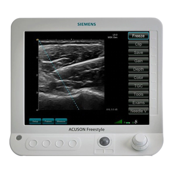
Introduction Imaging Screen Layout The console displays clinical images together with important operating parameters, patient data, and control commands. Sample Imaging Screen PATIENT NAME PATIENT ID L13-5 Nerve Gen 2.5cm CG 10 SC 3 SF 6 PP 10 55dB CF 1 CP 1 Vel 1 Pri 4... -
Page 21: Safety And Care
Siemens Authorized Care ........ - Page 22 Moving the System . . . . . . . . . . . . . . . . . . . . . . . . . . . . . . . . . . . . . . . . . . . . . . . . . . . . . 2-43 ACUSON Freestyle Rollstand Configuration ....... . . 2-44 System Upgrades .
-
Page 23: Operating Safety And Environment
Safety and Care Operating Safety and Environment Do not operate the ultrasound system until you fully understand the safety considerations and procedures presented in this manual. WARNING: Failure to comply with Warnings may pose a threat to patient and/or user safety. - Page 24 2002/96/EC on waste electrical and electronic equipment (WEEE), amended by directive 2003/108/EC. For collection and disposal of the product, its components, or its accessories, contact your local Siemens representative. Federal Communications Commission Manufacturer's declaration of product compliance with applicable EEC...
- Page 25 Safety and Care Symbol Explanation Bar Code Manufacturer Year of Manufacture symbol with the year below 20xx AC (alternating current) voltage source Indicates this side up Do not allow to get wet Fragile. Handle with care. IEEE 802.11b/g (WiFi) connected Battery (charge level) Power Plug I/O;...
-
Page 26: Intended Use
Safety and Care Intended Use WARNING: The analysis of results from an ultrasound examination requires that you are trained in the interpretation of diagnostic ultrasound studies and are qualified to make clinical diagnoses. Prescription Device Statement: In the United States of America, federal law restricts this device to sale or use by, or on the order of, a physician. -
Page 27: Indications For Use
Safety and Care Indications for Use The indications for use (intended use) for the Freestyle include fetal, abdominal, ACUSON intraoperative, intraoperative neurological, pediatric, small organs, neonatal cephalic, cardiac, peripheral vessel and vascular, and musculoskeletal. Scanning modes may include B-mode, Color Doppler, and Amplitude Doppler. Not all modes may be activated on the system or available with all transducers or for all indicated uses. -
Page 28: Pediatric
Safety and Care Pediatric Pediatric studies are performed in pediatric patients to obtain images that can be used to: detect presence or absence of organ abnormalities, detect abnormalities in superficial and bony structures, determine size, contour, and patency of vessels, and determine blood flow patterns and velocities. -
Page 29: Transducers And Intended Use
Safety and Care Transducers and Intended Use NOTE: Certain probes may require features not available on your system. Technical Data Transducer Name Frequency Range and Array Type Modes Intended Use Footprint L8-3 Linear B-Mode Fetal, abdominal, 3.0 – 8.0 MHz intraoperative, intraoperative neurological, Color Doppler... -
Page 30: Biohazard Considerations
Safety and Care Biohazard Considerations WARNING: Siemens makes every effort to manufacture safe and effective probes. You must take all necessary precautions to eliminate the possibility of exposing patients, operators, or third parties to hazardous or infectious materials. These precautions should be considered in the use of any application that may indicate the need for such care, for example, when scanning patients with open wounds. -
Page 31: Acoustic Output
Safety and Care Acoustic Output WARNING: Ultrasound procedures should be used for valid reasons, for the shortest period of time, and at the lowest mechanical/thermal index setting necessary to produce clinically acceptable images. NOTE: For ultrasound systems distributed in the United States of America, refer to the Medical Ultrasound Safety ultrasound education program brochure produced by the AIUM that is shipped with the system. -
Page 32: Acoustic Output: Global Maximum Values
Safety and Care Acoustic Output: Global Maximum Values No system/transducer combination is capable of exceeding either a Thermal Index (TI) of 1.0 or a Mechanical Index (MI) of 1.0, so, in accordance with relevant standards (NEMA UD3-2004), the system does not display MI or TI. The table below, Global Maximum Values, provides the mean of the global maximum of acoustic output values. -
Page 33: Acoustic Terms And Definitions
Safety and Care Acoustic Terms and Definitions Translations for language other than English. Term Definition Acoustic Output Global Maximum Values Term Definition ISPTA.3 (Intensity, spatial- peal temporal average) TI (Thermal Index) TIC (Thermal Index Cranial) TIS (Thermal Index Soft Tissue) TIB (Thermal Index Bone) MI (Mechanical Index) IPA.3@Mimax (Intensity,... - Page 34 Safety and Care Definition of Acoustic Terms Term Definition ISPTA .3 Intensity, spatial-peak temporal average: The value of the temporal- average intensity at the point in the acoustic field where the temporal- average intensity is a maximum, or is a local maximum within a specified region.
-
Page 35: Accuracies
Safety and Care Accuracies Measurement Accuracies Freestyle may be used to provide measurements and calculations derived from ACUSON ultrasound images. The quantified image data may be used along with other clinical information to assist a physician in making a patient diagnosis. The sole reliance on diagnostic ultrasound data to make a clinical diagnosis is not recommended. -
Page 36: Potential Sources Of Measurement Error During Scanning
Safety and Care Potential Sources of Measurement Error During Scanning The table below identifies potential sources of measurement error that may occur during scanning. Awareness of these sources can help you avoid errors they may cause. Potential Source of Error Explanation of Error Patient Variability The technical difficulty of patients in ultrasound imaging varies widely. -
Page 37: Electrical Safety
Safety and Care Electrical Safety WARNING: Explosion Hazard. Possible explosion hazard if used in the presence of flammable anesthetics. WARNING: To avoid electric shock, use a protective earth connection to connect the ultrasound system to the AC Mains power supply. The protective earth connection ensures that the mains circuit breaker will disconnect the power supply in the event of a short circuit. - Page 38 CAUTION: To ensure proper grounding and leakage current levels, it is the policy of Siemens to have an authorized Siemens representative or Siemens approved third party perform all on board connections of documentation and storage devices to the ultrasound system.
-
Page 39: Level Of Protection Against Electrical Shock For Probes
Safety and Care Level of Protection Against Electrical Shock for Probes According to EN 60601-1 and IEC 60601-1, the assemblies for the probes provide a “Level of Protection Against Electrical Shock” of “Type B.” The Type B icon is located on the probe and probe connector labels Defibrillators WARNING: To avoid the risk of injury to the operator, remove the probe from patient contact before the application of a high-voltage defibrillation pulse. -
Page 40: Implantable Devices
Safety and Care Implantable Devices WARNING: Ultrasound systems, like other medical equipment, use high-frequency electrical signals that can interfere with implantable devices such as pacemakers and implantable cardioverter-defibrillators (ICDs). If the patient has such an implantable device, you should be aware of any interference in its operation and immediately power off the ultrasound system. -
Page 41: Possible Combinations With Other Equipment And Peripheral Equipment
The ultrasound system supports a maximum of two documentation or storage devices connected to the system. Siemens recommends that you power off each device whenever the system is powered off. CAUTION: Any on-board peripheral devices must be installed by an authorized Siemens representative or by a Siemens-approved third party. - Page 42 Safety and Care Example of a peripheral equipment connection and patient environment Patient environment represented by shading, extending exactly 1.5 meters (1.83 meters [6 feet] in Canada and in the U.S.A.) around patient and ultrasound system Ultrasound system power cord Medically-approved isolation transformer power cord Medically-approved isolation transformer Peripheral equipment power cord...
- Page 43 Safety and Care Example of a peripheral equipment connection and patient environment 2.29 meters 1.5 meters (1.83 meters [6 feet] in Canada and the U.S.A.) Freestyle User Manual 2-23 ACUSON...
-
Page 44: Important Information For Maintaining Data Integrity
Safety and Care Important Information for Maintaining Data Integrity CAUTION: To prevent corruption of data stored on inserted media, do not interrupt the exporting process. Do not delete exported patient data from the local database until the exporting process is complete and the inserted media is determined to be full (or no more exporting is planned for the inserted media). -
Page 45: Caring For The Ultrasound System
Safety and Care Caring for the Ultrasound System It is the responsibility of the user to verify that the ultrasound system is safe for diagnostic operation on a daily basis. Each day, prior to using the system, perform each of the steps in the Daily Checklist. -
Page 46: Maintenance
■ The equipment is not used in accordance with the operating instructions. ■ The system is operated by personnel not adequately educated or trained. Siemens suggests that you request any person who performs maintenance or repairs to provide you with a certificate showing: ■... -
Page 47: Cleaning And Disinfecting
WARNING: To avoid electrical shock and damage to the ultrasound system, power off and unplug the equipment from the AC power outlet before cleaning and disinfecting. WARNING: Disinfectants and cleaning methods listed are recommended by Siemens for compatibility with product materials, not for biological effectiveness. Refer to disinfectant label instructions for guidance on disinfection efficacy and appropriate clinical uses. - Page 48 Safety and Care The following instructions describe cleaning the surface of the ultrasound system, including the Trackball and probe holder. See also, “Approved Disinfectant Wipes for the Ultrasound System Surfaces” on page 2-29. Do This Clean and disinfect 1. Power off the ultrasound system and unplug the power cord from the power the surface of the outlet.
-
Page 49: Approved Disinfectant Wipes For The Ultrasound System Surfaces
Safety and Care Approved Disinfectant Wipes for the Ultrasound System Surfaces The following matrix provides a list of approved disinfectant wipes for use on the ultrasound system and surfaces of the listed accessories. Sani-Cloth Sani-Cloth Sani-Cloth Super Sani- Sani-Cloth Bleach Wipe* Plus Cloth Ultrasound System... -
Page 50: Caring For Probes
Protective Case Due to the mechanical sensitivity of probes, Siemens recommends that you always use the probe case when you ship a probe or transport it from one place of examination to another. The case is specially designed to protect the sensitive parts of the probe. -
Page 51: Cleaning And Disinfecting Probes
Safety and Care Cleaning and Disinfecting Probes WARNING: Before cleaning and disinfecting, you must read and understand the cleaning and disinfecting topic, including the warnings and cautions for cleaning and disinfecting ultrasound system surfaces provided in this chapter. WARNING: Follow the instructions in this chapter, and your institution’s procedures to avoid risk of infection. -
Page 52: Intraoperative Neurological Important Warnings
WARNING: To avoid electrical shock and damage to the system, remove the probe battery or the probe adapter cable from the probe prior to cleaning or disinfecting. WARNING: Disinfectants and cleaning methods listed are recommended by Siemens for compatibility with product materials, not for biological effectiveness. Refer to disinfectant label instructions for guidance on disinfection efficacy and appropriate clinical uses. -
Page 53: Probe General Cleaning (Including Low Level Disinfection)
Safety and Care All probes should be cleaned and disinfected prior to their use on each patient. Probe General Cleaning (including Low Level Disinfection): Clean probes (including low level disinfection) after every patient use, including non-critical applications. Do not allow body fluids, such as blood, to dry on the probe. Routing cleaning steps are as follows: Immediately after completing the exam, turn the probe off and remove the battery module. -
Page 54: Probe High Level Disinfection
Safety and Care Probe High Level Disinfection Preparation Follow the Cleaning instructions above prior to high-level probe disinfection. High-Level Disinfection Soak the probe using a compatible disinfectant (listed below), following the manufacturer’s instructions and specifications. CAUTION: When disinfecting probes, be careful to immerse only the top portion of the probe, up to two inches (5 cm) from the transducer face in the disinfecting solution. -
Page 55: Probe Sterilization: Sterrad
Safety and Care Probe Sterilization: Sterrad The probe main module and battery module must be keep disassembled from each other, and packaged separately for sterilization. Carefully inspect the modules for cleanliness and dryness prior to packaging for Sterrad processing. If visible soil is present, the item must be re-cleaned and dried prior to sterilization. -
Page 56: Ipx8 Immersion Levels
Safety and Care IPX8 Immersion Levels CAUTION: To avoid damage to the probe, observe the continuous immersion levels indicated for each probe type. When disinfecting probes, be careful to continuously immerse only the top portion of the probe, up to two inches (5 cm) from the transducer face in the disinfecting solution. -
Page 57: Approved List Of Disinfectants
Safety and Care Approved List of Disinfectants The following matrix provides a list of approved disinfectants for all probes. NOTE: The approved disinfectants, such as Cidex OPA, may discolor probe housings, including the face of the probe. There is no associated degradation of imaging performance or probe reliability. -
Page 58: Caring For Probe Accessories
Ethylene Oxide (EO) methods. CAUTION: Siemens recommends that you follow all instructions provided by manufacturers of sterile goods (probe sheaths) to ensure proper handling, storage, and cycling of all sterile goods. -
Page 59: Recommended Use Of The Probe Sheaths
Safety and Care Recommended Use of the Probe Sheaths Siemens makes every effort to manufacture safe and effective probes. You must take all necessary precautions to eliminate the possibility of exposing patients, operators, or third parties to hazardous or infectious materials. These precautions should be considered in the use of any application that may indicate the need for such care, for example, when scanning patients with open wounds. -
Page 60: Battery Safety
To prevent the probe battery from bursting, igniting, or emitting fumes and causing personal injury or equipment damage, observe the following precautions. WARNING: Use only batteries supplied by Siemens Medical Solutions USA, Inc. with the system and probe. WARNING: Do not disassemble or alter the battery pack or remove the casing of the pack. - Page 61 CAUTION: Do not put the battery into a microwave oven or pressurized container. CAUTION: Store the battery between 5º C and 60º C (41º and 140º F). CAUTION: Use only Siemens-supplied batteries and charging devices. Freestyle User Manual 2-41...
-
Page 62: Good Ergonomic Practices
Safety and Care Good Ergonomic Practices WARNING: The operation of an ultrasound system may to linked to musculoskeletal disorders (MSDs). In ultrasound imaging, ergonomics may be defined as the physical interaction between the operator, the system, and the transducer, in the course of conducting exams. It is important for the operator of the system to practice good ergonomic techniques to reduce the risk of injury. -
Page 63: Moving The System
CAUTION: When moving the ultrasound system over longer distances, or shipping it, place it in the protective shipping case provided by Siemens and pack it according to the instructions. CAUTION: When moving the ultrasound system over longer distances, remove probe batteries from the probes. -
Page 64: Acuson Freestyle Rollstand Configuration
Safety and Care ACUSON Freestyle Rollstand Configuration WARNING: When operating and transporting the ultrasound system using the Freestyle ACUSON Rollstand, insure that the rollstand is configured according to the specifications provided in this manual. Failure to do so can cause the system to tip over and create a risk for injury to the user or patient and damage to the system. -
Page 65: System Upgrades
For more information, contact your local Siemens representative. To the extent required by local laws and regulations, Siemens has programs for the return of used products. For more information, contact your local Siemens representative. -
Page 66: Recycling Batteries
Recycle batteries according to local, state, and regional regulations. Use a battery collection program available in your country to recycle batteries. To the extent required by local laws and regulations, Siemens will collect and recycle batteries for this product at no charge. Contact your local Siemens representative for battery shipment instructions. -
Page 67: Disposing Of Components And Accessories
Safety and Care Disposing of Components and Accessories WARNING: Observe local, state, and regional regulations for the disposal of the ultrasound system components and accessories. Energy Conservation For improved energy conservation when the system is not in use, power off the system. Keep the system plugged into the power outlet. -
Page 68: Technical Description
Upon request, Siemens Medical Solutions USA, Inc. will make available circuit diagrams, component part lists, descriptions, calibration instructions, or other information that will assist service personnel to repair those parts of the system which are designated by Siemens Medical Solutions USA, Inc. as repairable by non-Siemens personnel. -
Page 69: System Setup
Setup 3 Setup This section describes the functions of the Setup Menu that is used to specify system settings. System Setup and Controls . . . . . . . . . . . . . . . . . . . . . . . . . . . . . . . . . . . . . . . . . . . . . . . 3-3 Overview of the Setup Menu . - Page 70 Setup Freestyle User Manual ACUSON...
-
Page 71: Setup
Setup System Setup and Controls This section explains how to setup the system. The Setup Menu includes patient data entry functions, patient study lists, system settings, and more. Overview of the Setup Menu To display the list of Setup options, press the Soft Key. -
Page 72: How To Select Items From The Setup Menu
Setup How to Select Items from the Setup Menu There are several ways to select an item from the menu list: SETUP ■ Turn the large, outer Rotary knob to highlight an item, then turn the small, inner Rotary knob to activate it. -
Page 73: Setup Menu Options
Setup Setup Menu Options Scan Activates the real-time imaging screen. When you are in a Setup page or menu the Soft SETUP Key changes to SCAN ■ To go to the real-time imaging screen from a Setup page, select SCAN ■... -
Page 74: Settings
Setup Settings The Settings options are used to configure the system: ■ User Exams ■ Network ■ DICOM User Exams Freestyle comes pre-loaded with a variety of factory exam types (e.g., cardiac, ACUSON vascular). This option lets you create custom User Exams with the parameters and settings that you specify. -
Page 75: System
Getting Help and Service Support Press the Soft Key to enter contact information for your local Service support HELPDESK representatives. Your Siemens Service Representative may access additional system information from the Helpdesk page. Closing the Active Page To close the active page select the option. -
Page 76: Patient Studies
Setup Administrative Options Soft Key provides a list of administrative settings for the system as described in the ADMIN following table. Admin Soft Key Settings Option Description Automatic Freeze When enabled, allows the system to freeze during real-time scanning when imaging is inactive. -
Page 77: Study List
Setup Option Description User Selected Keys Define shortcut keys that will appear in the Real-time Control bar. Two B-Mode and one Color shortcut can be defined. The function of the Probe middle keys can also be defined. Use the drop-down menus to specify the key functions. - Page 78 3-10 Freestyle User Manual ACUSON...
- Page 79 Patient Studies 4 Patient Studies This section describes how to create patient records and view, manage, and export patient studies. Protecting Patient Health Information . . . . . . . . . . . . . . . . . . . . . . . . . . . . . . . . . . . . . . . 4-3 About Patient Studies .
-
Page 80: Patient Studies
Patient Studies Freestyle User Manual ACUSON... -
Page 81: Protecting Patient Health Information
Patient Studies Protecting Patient Health Information Storing patient data on the Freestyle only temporarily, and then archiving the data to ACUSON your institution’s secured archival systems can enhance protection of your patient’s Protected Health Information (PHI). WARNING: Protected Health Information (PHI) such as patient records, is subject to privacy protection (such as is described in the US Health Insurance Accountability and Portability Act and the European Union Data Protection Directive, 95/46/EC.) Health care providers have a responsibility to protect PHI. -
Page 82: Patient Study Fields
Patient Studies Patient Study Fields To display the Patient Study fields press the Soft Key, then . When SETUP NEW PATIENT STUDY entering data into the Patient Study field, the [ key confirms an entry. The study information includes the fields described in the following table. Patient Study Information Fields Option(s) Description... -
Page 83: Patient Soft Keys
Patient Studies Patient Soft Keys Patient Soft Keys Soft Key Description SCAN Returns to the scan screen. Closes the record without saving unconfirmed entries. CANCEL CLEAR Lets you start over by clearing information from all the fields. WORKLIST Displayed if Worklist is configured for this system. For more information see, “Worklist Query”... -
Page 84: Using Patient Information From A Dicom Server
Patient Studies Using Patient Information from a DICOM Server If your system has the Worklist option and is configured and connected to a DICOM server you can obtain existing patient information (for more information, see “Overview of Connectivity” on page 8-3). Worklist Query This option provides a shortcut to entering patient information as you create new patient studies by accessing your DICOM Worklist Server (where patient information can be stored). -
Page 85: Factory Exam Types
Patient Studies Factory Exam Types The factory Exam Types provide real-time parameter presets optimized for specific types of exams (for information about creating user-defined exam types see “User Exams” on page 3-6). These standard exam types can help optimize imaging settings with minimal effort. Factory Exam Types are shown in the following table listed in alphabetical order. -
Page 86: User-Defined Exam Types
Patient Studies User-Defined Exam Types User defined Exam Types are preceded by “u”. You can create up to 64 different user exams. The User Exam page displays the list of User Exams that have been created, including the real-time settings by Probe type. Display the list of User Exams that have been created on the User Exams page: Press the Soft Key. -
Page 87: The Study List
Patient Studies The Study List The Study List includes all the patient study files that have been imaged and stored on the system. You can view studies from this list and send them (using the Export function) to a storage device such as a USB drive, or to a network destination such as a DICOM picture archival system (PACS). -
Page 88: Scrolling Through The Study List
Patient Studies Scrolling through the Study List To scroll through the study list, use the outer Rotary knobs. If a study contains saved images they are displayed as thumbnails. The inner knob highlights the images and allows you to view them full size. To return to scrolling through the Study List, turn the inner knob so the thumbnail image is no longer highlighted. -
Page 89: Managing Patient Studies
Patient Studies Managing Patient Studies Exporting Patient Studies The Export function sends selected studies to a storage medium (on a network or a compatible USB drive). How to Export Studies To export patient studies, follow these steps: Be sure you have the desired type of export hardware connected, e.g., a USB drive or a configured DICOM network. -
Page 90: Export Parameters
Patient Studies Export Parameters Pressing the Soft Key opens the Configure Export list with the following fields: EXPORT ■ Export Format: choose an export format: DICOM Network, DICOM Media, DICOM Media DSF (Decompressed Single Frame), or PC Viewable. DICOM Media and PC Viewable are used to store studies to a compatible USB external drive connected to the system. -
Page 91: Scanning
Scanning 5 Scanning This section describes the real-time scanning operation. Using the Probe . . . . . . . . . . . . . . . . . . . . . . . . . . . . . . . . . . . . . . . . . . . . . . . . . . . . . . . . . 5-3 About the Probe . - Page 92 Scanning Freestyle User Manual ACUSON...
-
Page 93: Using The Probe
Scanning Using the Probe About the Probe Probe Orientation The probe index marker is the side of the probe where the probe on/off symbol is located. This corresponds to the “a” symbol next to the image display. The probe model numbers, ACUSON such as “L8-3”... -
Page 94: Probe Controls
Scanning Probe Controls Functions in the real-time Control Bar can be adjusted or selected using the controls on the probe. These controls include the slider, the two circular buttons, and the two buttons in the middle of the probe. The slider mimics the function of the large Rotary knob on the console, moving the selection of the active item in the real-time control knob: ■... -
Page 95: Connecting The Probe
Scanning Connecting the Probe There are two ways to operate the probe with the system: ■ Cabled ■ Wireless Cabled Probe Operation To operate the probe with the removable probe Cable Adapter, plug the probe cable into the system I/O panel (see “Console Inputs/Outputs Panel” on page 1-5), and insert the probe end into the probe. -
Page 96: Wireless Probe Operation
Scanning Wireless Probe Operation To operate the system probe in wireless mode, insert a charged probe battery pack into the probe. NOTE: The battery pack is keyed to prevent improper connection. Do not use force when inserting the probe battery pack. ... -
Page 97: The Real-Time Scanning Screen
Scanning The Real-Time Scanning Screen L13-5 Nerve Gen 2.5cm CG 10 SC 3 SF 6 PP 10 55dB CF 1 CP 1 Vel 1 Pri 4 20 Hz ANL 0.0 dB Real-time Scanning Imaging Area Soft Keys ANL: Average Noise Level. A measure of wireless probe signal quality. See the Wireless Probe Operation chapter of the Manual for details about ANL. -
Page 98: Overview Of The Scanning Process
Scanning Overview of the Scanning Process Scanning is controlled using the Soft Keys, real-time Control Bar, and Rotary knobs. Basic steps to complete a scan and save it to the Study List: Press the console power button to turn the system on and allow it to boot up. To enter a new Patient Name and create a new Patient Study, press the Soft PATIENT... -
Page 99: Real-Time Scanning Controls
Scanning Real-Time Scanning Controls The Real-time Control Bar along the right side of the screen provides Soft Keys for the functions described in the following table. The larger, outer Rotary knob moves up or down the list, highlighting an active control. The smaller, inner Rotary knob adjusts the settings of the highlighted function. - Page 100 Scanning Real-time Control Bar Keys Description TGC (Time Gain Activates keys for Near, Mid, and Far Gain controls. “Auto” restores Compensation) default settings and “Exit” closes the TGC control list. 5-10 Freestyle User Manual ACUSON...
-
Page 101: Selecting An Exam Type From The List Of Exams
Scanning Selecting an Exam Type from the List of Exams Pressing the Soft Key on the Real-time Control Bar displays a list of factory Exam Exams Types and user-defined Exam Types that you can select from. Exam types provide presets of system controls in order to simplify optimization of images for different applications and patient types. -
Page 102: Scanning Soft Keys
Scanning Scanning Soft Keys The four Soft Keys along the bottom of the screen are controlled by the four circular buttons on the system console. They are described in the following table. Scanning Soft Keys Soft Key Description Displays the Setup page. SETUP PATIENT Displays the New Patient data entry page. -
Page 103: B-Mode Scanning
Scanning B-Mode Scanning The default scanning mode for the system is B-Mode. NOTE: Functions listed in the Tools menu will vary depending on how the System Administration / User Selected Keys are configured. B-Mode Tools The real-time Control Bar Tools Soft Key displays a number of secondary-level real-time imaging-related controls. - Page 104 Scanning Needle Visualization This setting improves the display of needles during procedures by brightening linear structures, such as needles, when they are perpendicular to steered frames activated by the user. It adjusts the system’s spatial compounding function to emphasize steering angles that may improve the display of needles.
-
Page 105: Color Flow Mode Scanning
Scanning Color Flow Mode Scanning Pressing on the real-time Control Bar activates color flow mapping mode. This key Color switches color flow on and off. In color flow mode the real-time controls include: – Color Gain controls the color flow overall gain. C Gain –... -
Page 106: Measurements
Scanning Measurements Performing a Measurement The measurements function can be performed from real-time scanning or starting with a frozen image. Up to ten individual measurements can be made on an image. To perform measurements on an image: Press the Soft Key. The image will freeze and the measurement choices will MEASURE appear in a menu above the key. -
Page 107: Area Measurement
Scanning Area Measurement To perform an area measurement: Activate the Area function by selecting from the sub-menu. AREA MEASURE Position the cross-hair cursor at the starting point by pressing the left Trackball button. NOTE: If you have selected the continuous trace method in the SETUP SYSTEM page, use the Trackball to trace the area. -
Page 108: Adding Text Annotations To Studies
Scanning Adding Text Annotations to Studies Text labels can be added and saved to images. To add text annotations or a pointer to an image screen: Press the Soft Key. Text Use the controls described in the Text Annotation Functions table to add text labels. To exit Text mode, press the Soft Key. - Page 109 Wireless Probes 6 Wireless Probes This chapter contains information about operating the Freestyle system with wireless ACUSON probes. Overview............. . . 6-3 Antenna Locations .
-
Page 110: Wireless Probes
Wireless Probes Freestyle User Manual ACUSON... -
Page 111: Overview
Wireless Probes Overview When the system is operated in “wireless mode” the probe Cable Adapter is not used; instead, the probe and console communicate wirelessly. To obtain successful results scanning wirelessly, follow the instructions provided here. NOTE: Consult the Safety chapter and System Reference manual for important information about wireless operation and electromagnetic compatibility issues associated with the system. -
Page 112: Equipment Setup For Optimal Scanning
Wireless Probes Equipment Setup for Optimal Scanning The radio frequency (RF) transmitters used in the Freestyle to send image data from ACUSON the probe to the console are designed to cover distances of no more than three (3) meters. It is important to make sure that the distance between the probe and the console does not exceed three (3) meters. -
Page 113: Connecting A Wireless Probe
Wireless Probes Connecting a Wireless Probe NOTE: For important information about the Wireless Signal Quality meter and the Average Noise Level index which are displayed during wireless scanning, see “Wireless Signal Quality” on page 6-6 in this chapter. To connect a wireless probe to the system: With the console unit powered on, hold the probe within three meters of the console, with a line-of-sight to the front of the console, and without obstructions between the probe and the console. -
Page 114: Wireless Signal Quality
Wireless Probes Wireless Signal Quality The Freestyle console has a wireless signal quality meter that represents the wireless probe signal quality. Always position the probe and system to maximize the signal quality. By staying inside the 3 meter range and maintaining a good line-of-sight between the probe and the console —... -
Page 115: Monitoring Wireless Signal Quality
Wireless Probes Monitoring Wireless Signal Quality The Freestyle has two methods of monitoring wireless signals: ■ Wireless Signal Quality meter ■ Average Noise Level indicator Each is described in the following sections. Wireless Signal Quality Meter The signal meter has a total of six bars. No Signal No Signal Wireless Signal Quality Meter;... -
Page 116: Average Noise Level Indicator
Wireless Probes Average Noise Level Indicator An additional indicator of wireless imaging quality, called the Average Noise Level (ANL) has been calculated for various conditions. ANL is another tool to guide wireless scanning. It provides a measure of the potential for a compromised wireless link to introduce noise artifact into the image. - Page 117 Wireless Probes The wireless Average Noise Level (ANL) is displayed in real-time. Examples are provided above. Values above the 0.0 level reflect an increased possibility of noise being introduced into the image because of a compromised wireless link. The upper range is approximately 4.0 dB. For best results position the probe and system such that ANL is not above 1.0 dB.
-
Page 118: Wireless Noise Examples
Wireless Probes Wireless Noise Examples B-Mode Wireless Noise In B-Mode, if the wireless signal quality is compromised, noise may occur as shown in the simulated image below. If you experience such noise, reposition to improve the link quality. B-Mode wireless noise (simulated image) Reasons for a Low Wireless Signal in B-Mode ■... -
Page 119: Finding/Locating Wireless Probes
Wireless Probes Finding/Locating Wireless Probes It is very important to carefully manage the location of your wireless probes and not misplace them. Do not leave probes behind when performing mobile procedures. The system provides a means of assisting in preventing the unintentional separation of the wireless probe from the console. -
Page 120: Using Multiple Probes
Wireless Probes Using Multiple Probes Multiple probes can be used with the system, but only one probe can be activated at a time. More than One Wireless Probe To use more than one probe in wireless mode during an exam: Turn the currently-connected probe off, thereby disconnecting it from the console. -
Page 121: Batteries
Batteries 7 Batteries This chapter contains information regarding the battery operation of the system and wireless probes. Overview of the Probe Battery . . . . . . . . . . . . . . . . . . . . . . . . . . . . . . . . . . . . . . . . . . . . . 7-3 Charging the Probe Battery . - Page 122 Batteries Freestyle User Manual ACUSON...
-
Page 123: Overview Of The Probe Battery
Batteries Overview of the Probe Battery WARNING: Read the Safety Chapter of this manual for important information regarding safe operation of the Freestyle batteries. ACUSON WARNING: To avoid the risk of electrical shock, do not insert the battery pack into probe or charger bays unless the battery pack, probe, or charger bays are dry and free of liquids. -
Page 124: Charging The Probe Battery
Batteries Charging the Probe Battery Successful wireless probe scanning without interruption requires a properly charged battery pack. To charge the probe batteries, use the on-board two-port charging bays built into the back of the console. For optimal charging in the console charging ports, the console should be plugged into AC Mains power outlet. -
Page 125: Inserting The Battery Into The Probe
Batteries Inserting the Battery into the Probe To insert a charged battery pack into a probe: Place the metal contact side facing into the well on the probe with the label facing down and the metal contacts towards the back of the probe. CAUTION: The battery pack is keyed to fit into the probe in the proper orientation. -
Page 126: Low Battery Alerts
Batteries Low Battery Alerts A pop-up message on the console will alert you when the probe battery approaches approximately 20% of remaining power. You should then take action to avoid an interruption to the exam: the image. Freeze Turn the probe off. Replace the probe battery with a fresh battery. -
Page 127: Connectivity
Connectivity 8 Connectivity This chapter tells you how to configure your system for connectivity, and how to operate connectivity commands. Overview of Connectivity . . . . . . . . . . . . . . . . . . . . . . . . . . . . . . . . . . . . . . . . . . . . . . . . . 8-3 Configuring the Network Settings . - Page 128 Connectivity Freestyle User Manual ACUSON...
-
Page 129: Connectivity
Connectivity Overview of Connectivity Freestyle includes the DICOM (Digital Imaging and Communications in Medicine) ACUSON networking capability. DICOM communications comply with the DICOM standard and provide links between the system and DICOM picture archival systems (PACS), modality worklist servers, and storage commitment servers. Consult with your PACS Administrator when using the DICOM features of the ACUSON Freestyle. -
Page 130: Wireless Network Setup
Connectivity Wireless Network Setup NOTE: The term “WiFi” is used here to represent the wireless networking standard IEEE 802.11b/g. Refer to the Safety chapter of this Manual and the System Reference Manual for important information about the operation of IEEE 802.11b/g on the Freestyle. -
Page 131: Configuring The Wifi Network
Connectivity Configuring the WiFi Network WiFi Network Configuration Fields Network Field Description Network Name Unique name to identify the network in the Network List. Network Type Select either Infrastructure or Adhoc. • Infrastructure uses central access points such as routers for communication. -
Page 132: Configuring The Dicom Setup
Connectivity Configuring the DICOM Setup To access the DICOM setup menus, select SETUP SETTINGS DICOM DICOM Configuration Fields DICOM Field Description PACS Configures the Freestyle to link to a DICOM-compliant ACUSON Picture Archival and Communications System (PACS). Storage Commitment When on, supported by your PACS system and, configured on the ultrasound system, confirms that a study has been received and stored by the target device. -
Page 133: Configuring A Dicom Storage Server
Connectivity Configuring a DICOM Storage Server To configure a DICOM storage server, Go to SETUP SETTINGS DICOM PACS Select New. Enter the DICOM storage server information as described in the following table. DICOM Storage Server Fields DICOM Storage Server Description Field Alias A name you create to identify the DICOM server. -
Page 134: Configuring A Dicom Storage Commitment Server
Connectivity Configuring a DICOM Storage Commitment Server To configure a DICOM Storage Commitment Server: Go to SETUP SETTINGS DICOM STORAGE COMMITMENT Select Enter the DICOM Storage Commitment information as described in the following table. DICOM Storage Commitment Fields Field Description Alias Name you define for the Storage Commitment Server. -
Page 135: Configuring A Modality Worklist Server
Connectivity Configuring a Modality Worklist Server To configure a DICOM Modality Worklist Server: Go to SETUP SETTINGS DICOM WORKLIST Select Enter the DICOM Worklist information as described in the following table. DICOM Worklist Fields Field Description Alias Name you define for the server. Limited to 16 characters. -
Page 136: Configuring The System Dicom Settings
Connectivity Configuring the System DICOM Settings To configure the Freestyle System DICOM settings: ACUSON Go to SETUP SETTINGS DICOM SYSTEM Enter the system information as described in the following table. DICOM System Settings Fields Field Description Freestyle AE Title Identifies the AE Title assigned to the system. Limited to 16 characters;... -
Page 137: Freestyle Mobile Link App
Connectivity Freestyle Mobile Link App NOTE: Images displayed using the App are for informational purposes only and are not intended for diagnostic use. For instructions on using the Mobile Link App on a mobile device, see the instructions provided with the App. Freestyle Mobile Link Settings Freestyle Mobile Link App Settings Function... -
Page 138: Privacy And Security
Connectivity Privacy and Security To insure proper protection of Protected Health Information and networking security when using the App, note the following recommendations and instructions. ■ For important information about 802.11 (WiFi), refer to the Freestyle User Manual and System Reference Manual. ■...