Siemens SIMATIC S7-1500 System Manual
Automation system
Hide thumbs
Also See for SIMATIC S7-1500:
- Function manual (402 pages) ,
- System manual (393 pages) ,
- Manual (188 pages)

Related Manuals for Siemens SIMATIC S7-1500


Summary of Contents for Siemens SIMATIC S7-1500
- Page 2 ___________________ Automation system Preface ___________________ Documentation guide ___________________ System overview ___________________ SIMATIC Application planning ___________________ Installation S7-1500, ET 200MP ___________________ Automation system Wiring ___________________ Configuring ___________________ Basics of program processing System Manual ___________________ Protection ___________________ Flexible automation concepts ___________________ Commissioning SIMATIC memory card ___________________ CPU display...
- Page 3 Note the following: WARNING Siemens products may only be used for the applications described in the catalog and in the relevant technical documentation. If products and components from other manufacturers are used, these must be recommended or approved by Siemens. Proper transport, storage, installation, assembly, commissioning, operation and maintenance are required to ensure that the products operate safely and without any problems.
-
Page 4: Preface
Basic knowledge required A basic knowledge of automation technology is required to understand the documentation. Scope of validity of the documentation This documentation is valid for all products from the SIMATIC S7-1500 and SIMATIC ET 200MP product families. Conventions STEP 7: In this documentation, "STEP 7" is used as a synonym for all versions of the configuration and programming software "STEP 7 (TIA Portal)". - Page 5 Please go online (https://www.automation.siemens.com/WW/newsletter/guiThemes2Select.aspx?HTTPS=RE DIR&subjectID=2) and register for the following newsletters: • SIMATIC S7-300/S7-300F • SIMATIC S7-400/S7-400H/S7-400F/FH • SIMATIC S7-1500/SIMATIC S7-1500F • Distributed I/O • SIMATIC Industrial Software Select the "Current" check box for these newsletters. Note...
- Page 6 Siemens recommends strongly that you regularly check for product updates. For the secure operation of Siemens products and solutions, it is necessary to take suitable preventive action (e.g. cell protection concept) and integrate each component into a holistic, state-of-the-art industrial security concept.
-
Page 7: Table Of Contents
Table of contents Preface ..............................4 Documentation guide ..........................11 System overview ........................... 13 What is the SIMATIC S7-1500 automation system? .............. 13 What is the SIMATIC ET 200MP distributed I/O system? ............16 Components ..........................19 Application planning ..........................23 Hardware configuration ...................... - Page 8 Table of contents Connecting interfaces for communication ................64 Front connector for the I/O modules ..................65 5.8.1 Wiring front connectors for I/O modules without shield contact element ....... 67 5.8.2 Wiring front connectors for I/O modules with shield contact element ........70 5.8.3 Bringing the front connector into final position ...............
- Page 9 Table of contents Flexible automation concepts ......................123 Standard machine projects ....................123 Configuration control ......................124 9.2.1 Rules ............................. 126 9.2.2 Control data record for the S7-1500 Automation System ............. 128 9.2.3 Control data record for the ET 200MP distributed I/O system ..........130 9.2.4 Feedback data record of the ET 200MP distributed I/O system ...........
- Page 10 Table of contents Maintenance ............................183 13.1 Removing and inserting I/O modules ................... 183 13.2 Replacement of I/O modules and front connectors ............. 184 13.2.1 Coding element on the I/O module and on the front connector ........... 184 13.2.2 Replacing an I/O module ..................... 186 13.2.3 Replacing a front connector ....................
-
Page 11: Documentation Guide
This arrangement enables you to access the specific content you require. Basic information System Manual and Getting Started describe in detail the configuration, installation, wiring and commissioning of the SIMATIC S7-1500 and ET 200MP systems. The STEP 7 online help supports you in the configuration and programming. Device information Product manuals contain a compact description of the module-specific information, such as properties, terminal diagrams, characteristics and technical specifications. - Page 12 Documentation guide Manual Collection S7-1500/ET 200MP The Manual Collection contains the complete documentation on the SIMATIC S7-1500 automation system and the ET 200MP distributed I/O system gathered together in one file. You can find the Manual Collection on the Internet (http://support.automation.siemens.com/WW/view/en/86140384).
-
Page 13: System Overview
System overview What is the SIMATIC S7-1500 automation system? SIMATIC S7-1500 The SIMATIC S7-1500 automation system is the further development of the SIMATIC S7-300 and S7-400 automation systems. Through the integration of numerous new performance features, the S7-1500 automation system offers you excellent operability and the highest performance. - Page 14 System overview 2.1 What is the SIMATIC S7-1500 automation system? Customer benefits of the system Figure 2-1 SIMATIC S7-1500 automation system - Customer benefits Field of application The S7-1500 automation system offers the required flexibility and performance for a high bandwidth of controller applications in machine and plant engineering.
- Page 15 System overview 2.1 What is the SIMATIC S7-1500 automation system? Configuration The SIMATIC S7-1500 automation system is made up of the following components: ● CPU ● Digital and analog I/O modules ● Communications modules (PROFINET/Ethernet, PROFIBUS, point-to-point) ● Technology modules (counting, position detection) ●...
-
Page 16: What Is The Simatic Et 200Mp Distributed I/O System
System overview 2.2 What is the SIMATIC ET 200MP distributed I/O system? What is the SIMATIC ET 200MP distributed I/O system? SIMATIC ET 200MP The ET 200MP is a scalable and highly flexible distributed I/O system for connecting the process signals to a central controller via fieldbus. Customer benefits of the system Figure 2-3 SIMATIC ET 200MP distributed I/O system - customer benefits... - Page 17 System overview 2.2 What is the SIMATIC ET 200MP distributed I/O system? Configuration The SIMATIC ET 200MP distributed I/O system is made up of the following components: ● Interface module (PROFINET or PROFIBUS) ● Digital and analog I/O modules ● Communications modules (point-to-point) ●...
- Page 18 System overview 2.2 What is the SIMATIC ET 200MP distributed I/O system? Example of a configuration with the IM 155-5 DP ST interface module ① Interface module ② I/O modules ③ Mounting rail with integrated DIN rail profile Figure 2-5 Example of a configuration of the ET 200MP with IM 155-5 DP ST See also Accessories/spare parts (Page 224)
-
Page 19: Components
System overview 2.3 Components Components Components of the S7-1500 automation system/ET 200MP distributed I/O system Table 2- 1 Components S7-1500/ET 200MP Components Function Diagram Mounting rail The mounting rail is the rack of the S7-1500 automation system. You can use the entire length of the mounting rail (marginless assembly). The mounting rails may be ordered as accessories (Page 224). - Page 20 System overview 2.3 Components Components Function Diagram Interface module for The interface module: PROFIBUS DP Can be used as DP slave on PROFIBUS DP • Links the ET 200MP distributed I/O system with the DP master. • Exchanges data with the I/O modules via the backplane bus. •...
- Page 21 System overview 2.3 Components Components Function Diagram Shielding bracket The shielding bracket is an insertable bracket for modules with EMC-critical signals (e.g., analog modules, technology modules), and (together with the shielding clamp) permits the low impedance application of shielding with minimal installation times. The shielding bracket is included in the scope of delivery of the analog and technology modules, and may be ordered as an accessory (Page 224).
- Page 22 System overview 2.3 Components Components Function Diagram Load current supply The system power supply (PS), central modules (CPU), input and (PM) output circuits of the I/O modules are supplied with 24 V DC through the load current supply (PM). A load current supply does not occupy a slot in the configuration and is not included in the system diagnostics.
-
Page 23: Application Planning
Application planning Hardware configuration Introduction The S7-1500 automation system/ET 200MP distributed I/O system consists of a single-row configuration in which all modules are installed on one mounting rail. The modules are connected by means of U connectors, and thus form a self-assembling backplane bus. 3.1.1 Hardware configuration of the S7-1500 automation system Maximum configuration... - Page 24 Application planning 3.1 Hardware configuration Applicable modules The following table shows which modules may be used in the various slots: Table 3- 1 Assignment of slot numbers Module type Permissible slots Maximum number of modules Load current supply (PM) Unlimited / only 1 PM can be configured in STEP 7 System power supply (PS) 0;...
-
Page 25: Hardware Configuration Of The Et 200Mp Distributed I/O System With Profinet Interface Module
Application planning 3.1 Hardware configuration 3.1.2 Hardware configuration of the ET 200MP distributed I/O system with PROFINET interface module Maximum configuration ● The integrated system power supply of the interface module feeds 14 W into the backplane bus. The exact number of the I/O modules operated with the interface module depends on the power budget (see section Power balance calculation (Page 34)). -
Page 26: Hardware Configuration Of The Et 200Mp Distributed I/O System With Profibus Interface Module
Application planning 3.2 System and load power supply 3.1.3 Hardware configuration of the ET 200MP distributed I/O system with PROFIBUS interface module Maximum configuration The integrated system power supply of the interface module feeds 14 W into the backplane bus. The exact number of the I/O modules operated with the interface module depends on the power budget (see section Power balance calculation (Page 34)). -
Page 27: System And Load Power Supply
Application planning 3.2 System and load power supply System and load power supply Types of power supplies The S7-1500 automation system/ET 200MP distributed I/O system distinguishes between two types of power supply: ● System power supply (PS) ● Load current supply (PM) System power supply (PS) The system power supply has a connection to the backplane bus (U connector) and supplies solely the internally required system voltage. - Page 28 Application planning 3.2 System and load power supply Total configuration with power supplies Figure 3-4 Total configuration with load current supply (PM) and system power supply (PS) Optionally, you can insert up to two system power supplies (PS) in the slots to the right of the CPU/interface module (power segments).
-
Page 29: Use Of System Power Supplies
Application planning 3.2 System and load power supply 3.2.1 Use of system power supplies Introduction If the power fed from the CPU/interface module into the backplane bus is not sufficient to supply all connected modules with power, system power supplies (PS) are required. You can also use system power supplies with 120/230 V AC and supply the CPU/interface module by means of the backplane bus. - Page 30 (Page 34). Additional information on the performance values (power feed, power consumption) of the CPU, interface module, system power supply, and I/O modules can be found in the manuals (http://support.automation.siemens.com/WW/view/en/57251228) of the respective modules. Automation system System Manual, 12/2014, A5E03461182-AC...
-
Page 31: Special Considerations For The Use Of A System Power Supply In The First Power
Application planning 3.2 System and load power supply 3.2.2 Special considerations for the use of a system power supply in the first power segment Infeed options There are three options for the infeed of the required system voltage in the backplane bus: ●... - Page 32 Application planning 3.2 System and load power supply Procedure To set up the supply by means of the CPU/interface module and system power supply, follow these steps: 1. Open the "Properties" tab of the CPU/interface module in STEP 7 and select the "System power supply"...
-
Page 33: Use Of Load Power Supplies
24 V DC from the control cabinet. Reference More information on load current supplies can be found on the Internet (https://mall.industry.siemens.com) in the online catalog and in the online ordering system. Automation system System Manual, 12/2014, A5E03461182-AC... -
Page 34: Power Balance Calculation
Application planning 3.4 Power balance calculation Power balance calculation Principle of power balance calculation In order to ensure the supply of the modules from the backplane bus, the infed power is compared with the required power. The power balance calculation checks whether the power provided by the system power supplies including CPU/interface module is greater than or equal to the power used by the consumers (modules). - Page 35 Application planning 3.4 Power balance calculation Power balance calculation during planning with STEP 7 STEP 7 checks compliance with the power balance during the configuration. Proceed as follows to evaluate the power balance calculation: 1. Perform the configuration of the S7-1500/ET 200MP with all the required modules. 2.
- Page 36 Application planning 3.4 Power balance calculation Response of the CPU to negative power balance or failure of system power supplies As soon as a negative power balance/overload is detected by the CPU in a power segment, the following actions are executed: ●...
-
Page 37: Installation
Installation Basics Introduction All modules of the S7-1500 automation system/ET 200MP distributed I/O system are open equipment. This means that you may only install this system in housings, cabinets or electrical operating rooms. These housings, cabinets or electrical operating rooms must only be accessible with a key or tool. - Page 38 Installation 4.1 Basics Minimum clearances Modules can be mounted up to the outer edge of the mounting rail. Maintain the following minimum clearances at the top and bottom when installing or removing the S7-1500 automation system/ET 200MP distributed I/O system. ①...
-
Page 39: Installing The Mounting Rail
Installation 4.2 Installing the mounting rail Installing the mounting rail Lengths and drill holes The mounting rails are delivered in five lengths: ● 160 mm ● 245 mm ● 482.6 mm (19 inches) ● 530 mm ● 830 mm ● 2000 mm The part numbers can be found in the Accessories/spare parts (Page 224) section. - Page 40 Installation 4.2 Installing the mounting rail Required accessories You can use the following screw types for fastening of the mounting rails: Table 4- 1 Required accessories For ... you can use ... Explanation M6 fillister head screws according to Choose a suitable screw length for your outer fixing screws •...
- Page 41 Installation 4.2 Installing the mounting rail Preparing the 2000 mm mounting rail for installation To prepare the 2000 mm mounting rail for installation, follow these steps: 1. Cut the 2000 mm mounting rail to the required length. 2. Mark the holes. The necessary dimensions can be found in the table "Dimensions for the drill holes": –...
- Page 42 Installation 4.2 Installing the mounting rail Attaching the protective conductor The S7-1500 automation system/ ET 200MP distributed I/O system has to be connected to the protective conductor system of the electrical system to ensure electrical safety. To connect the protective conductor, follow these steps: 1.
-
Page 43: Installing A System Power Supply
Installation 4.3 Installing a system power supply Installing a system power supply Introduction The system power supply has a connection to the backplane bus and supplies the configured modules with the internal supply voltage. Requirements The mounting rail is installed. Tools required Screwdriver with 4.5 mm blade Installing a system power supply... -
Page 44: Installing A Load Current Supply
Installation 4.4 Installing a load current supply Uninstalling a system power supply The system power supply is wired up. To uninstall the system power supply, follow these steps: 1. Turn off the feed supply voltage. 2. Open the front cover. 3. - Page 45 Installation 4.4 Installing a load current supply Installing a load current supply To install a load current supply, follow these steps: 1. Hook the load current supply on the mounting rail. 2. Swivel the load current supply to the rear. Figure 4-5 Installing a load current supply 3.
-
Page 46: Installing The Cpu
Installation 4.5 Installing the CPU Uninstalling the load current supply The load current supply is wired up. To uninstall a load current supply, follow these steps: 1. Turn off the feed supply voltage. 2. Open the front cover. 3. Shut down the load current supply. 4. - Page 47 Installation 4.5 Installing the CPU Installing the CPU To install a CPU, follow these steps: 1. Insert a U-connector into the back right on the CPU. 2. Hook the CPU on the mounting rail and slide the CPU up to the left-hand system power supply.
-
Page 48: Installing The Interface Module
Screwdriver with 4.5 mm blade Installing the interface module Watch video sequence (http://cache.automation.siemens.com/media/67462859_installing_web_en/start.htm) To install an interface module, proceed as follows: 1. Mount the U-connector on the back right-hand side of the interface module. 2. Hook the interface module on the rail. -
Page 49: Installing I/O Modules
Installation 4.7 Installing I/O modules Uninstalling the interface module The interface module is wired and is followed by additional modules. To uninstall the interface module, follow these steps: 1. Switch off the supply voltage for the interface module. 2. Open the front cover. 3. - Page 50 Installation 4.7 Installing I/O modules Installing I/O modules Proceed as follows to install an I/O module: 1. Insert a U connector into the back right on the I/O module. Exception: the last I/O module in the assembly 2. Hook the I/O module on the mounting rail and slide the I/O module up to module on the left.
-
Page 51: Wiring
Wiring Rules and regulations for operation Introduction When installing the S7-1500 automation system/ ET 200MP distributed I/O system as part of a plant or system, special rules and regulations need to be adhered to depending on the area of application. This section provides an overview of the most important rules that must be observed for the integration of the S7-1500 automation system/ ET 200MP distributed I/O system in a plant or system. - Page 52 Suitable components for the lightning and overvoltage protection are specified in the Defining interference-free controllers (http://support.automation.siemens.com/WW/view/en/59193566) function manual. Protection against electrical shock The mounting rail of the S7-1500 automation system/ET 200MP distributed I/O system has to be connected conductively with the protective conductor as protection against electrical shock.
-
Page 53: Operation On Grounded Infeed
Wiring 5.2 Operation on grounded infeed Operation on grounded infeed Introduction Information is provided below on the overall configuration of an S7-1500 automation system/ET 200MP distributed I/O system on a grounded infeed (TN-S system). The specific subjects discussed are: ● Disconnecting devices, short-circuit and overload protection to IEC 60364 (corresponding to DIN VDE 0100) and IEC 60204 (corresponding to DIN VDE 0113) ●... - Page 54 Wiring 5.2 Operation on grounded infeed Short-circuit and overload protection Various measures as protection against short-circuits and overloads are required for setting up a full installation. The nature of the components and the degree to which the required measures are binding depends on the IEC (DIN VDE) regulation applicable to your plant configuration.
- Page 55 Wiring 5.2 Operation on grounded infeed S7-1500/ET 200MP in the overall configuration The figure below shows the overall configuration of the S7-1500/ET 200MP (load current supply and grounding concept) with infeed from a TN-S system. ① Main switch ② Short-circuit and overload protection on the primary side ③...
-
Page 56: Electrical Configuration
Wiring 5.3 Electrical configuration Electrical configuration Galvanic isolation With the S7-1500 automation system/ET 200MP distributed I/O system, there is galvanic isolation between: ● The primary side of the system power supply (PS) and all other circuit components ● The (PROFIBUS/PROFINET) communication interfaces of the CPU/interface module and all other circuit components ●... - Page 57 Wiring 5.3 Electrical configuration Potential relationships ET 200MP on PROFINET IO The following figure shows a simplified representation of the potential relationships of the ET 200MP distributed I/O system on PROFINET IO. Figure 5-3 Potential relationships for ET 200MP using an IM 155-5 PN HF interface module as an example Automation system System Manual, 12/2014, A5E03461182-AC...
- Page 58 Wiring 5.3 Electrical configuration Potential relationships ET 200MP on PROFIBUS DP The following figure shows a simplified representation of the potential relationships of the ET 200MP distributed I/O system on PROFIBUS DP. Figure 5-4 Potential relationships for ET 200MP using an IM 155-5 DP ST interface module as an example Automation system System Manual, 12/2014, A5E03461182-AC...
-
Page 59: Wiring Rules
Wiring 5.4 Wiring rules Wiring rules Table 5- 2 Wiring rules for CPU, interface module, system power supply and load current supply Wiring rules for... CPU/interface module System power and load current supply Connectible conductor cross-sections for solid wires Connectible conductor Without end sleeve 0.25 to 2.5 mm 1.5 mm... - Page 60 Wiring 5.5 Connecting the supply voltage Table 5- 3 Wiring rules for front connector Wiring rules for... 40-pin front connector 40-pin front connector 40-pin front connector (screw terminal, (push-in terminal, (push-in terminal, for 35 mm module) for 35 mm module) for 25 mm module) Connectible conductor cross-sections for solid up to 0.25 mm²...
-
Page 61: Connecting The Supply Voltage
Wiring 5.5 Connecting the supply voltage Connecting the supply voltage Introduction The supply voltage of the CPU/interface module is supplied by means of a 4-pole connection plug, which is located on the front of the CPU. Connection for supply voltage (X80) The connections of the 4-pole connector have the following meaning: ①... -
Page 62: Connecting System Power Supply And Load Current Supply
Wiring 5.6 Connecting system power supply and load current supply Connection of wires: multi-wire (stranded), without end sleeve, unprocessed To connect a wire without end sleeve, follow these steps: 1. Strip 8 to 11 mm of the wires. 2. Using a screwdriver, press the spring release and insert the wire into the push-in terminal as far as it will go. - Page 63 5.6 Connecting system power supply and load current supply Connecting the supply voltage to a system power supply/load current supply Watch video sequence (http://cache.automation.siemens.com/media/67462859_connecting_supply_web_en/start.ht To connect the supply voltage, follow these steps: 1. Swing the front cover of the module up until the front cover latches.
-
Page 64: Connecting Interfaces For Communication
Wiring 5.7 Connecting interfaces for communication Reference Further information about connecting the 24 V DC output voltage of the load voltage supply modules is available in the manuals of the corresponding modules. Connecting interfaces for communication Connecting interfaces for communication The communication interfaces of the CPU/interface module are connected using standardized connectors. -
Page 65: Front Connector For The I/O Modules
Wiring 5.8 Front connector for the I/O modules Front connector for the I/O modules Introduction The sensors and actuators of your plant are connected to the automation system by means of front connectors. Wire the sensors and actuators to the front connector and then plug it into the I/O module. - Page 66 Wiring 5.8 Front connector for the I/O modules Properties of the front connectors The three different front connectors are characterized as follows: ● 40 clamping points each ● Connection technology: Screw terminal (for 35 mm modules only) or push-in terminal ●...
-
Page 67: Wiring Front Connectors For I/O Modules Without Shield Contact Element
Wiring 5.8 Front connector for the I/O modules 5.8.1 Wiring front connectors for I/O modules without shield contact element Requirements ● The I/O modules are installed on the mounting rail. ● The supply voltages are turned off. ● The wires are prepared according to the utilized clamping technology, take the wiring rules (Page 59) into account for this purpose. - Page 68 3. Swing the front cover of the wired I/O module up until the front cover latches (Figure 2). Watch video sequence (http://cache.automation.siemens.com/media/67462859_wiring_front_web_en/start.htm) 4. Bring the front connector into the pre-wiring position. To do this, hook the front connector into the bottom of the I/O module and swivel the front connector upward until the front connector latches (Figure 3).
- Page 69 Wiring 5.8 Front connector for the I/O modules Figure 5-9 Wiring front connectors for I/O modules without shield contact element 5. Begin to completely wire the front connector. 6. Put the strain relief around the cable harness, and pull the strain relief for the cable harness tight.
-
Page 70: Wiring Front Connectors For I/O Modules With Shield Contact Element
Wiring 5.8 Front connector for the I/O modules 5.8.2 Wiring front connectors for I/O modules with shield contact element Requirements ● The I/O modules are installed on the mounting rail. ● The supply voltages are turned off. ● The wires are prepared according to the clamping technology used. To do this, follow the wiring rules (Page 59). - Page 71 5.8 Front connector for the I/O modules Preparing front connectors for I/O modules with shield contact element Watch video sequence (http://cache.automation.siemens.com/media/67462859_wiring_shield_web_en/start.htm) To prepare the front connector for wiring, follow these steps: 1. Remove the connection separator from the lower part of the connector (Figure 1).
- Page 72 Wiring 5.8 Front connector for the I/O modules 5. Swing the front cover up until the front cover latches (Figure 5). 6. Bring the front connector into the pre-wiring position. To do this, hook the front connector into the bottom of the I/O module and swivel it upwards until the front connector latches (Figure 6).
- Page 73 Wiring 5.8 Front connector for the I/O modules 7. Wire the power supply element (Figure 8). Terminals 41/42 and 43/44 are galvanically connected to each other. If you connect the supply voltage to 41 (L+) and 44 (M), you can then loop-through the potential to the next module with terminals 42 (L+) and 43 (M).
- Page 74 Wiring 5.8 Front connector for the I/O modules 3. Put the strain relief (cable tie) around the cable harness, and pull the strain relief for the cable harness tight (Figure 2). Figure 5-15 Wiring front connectors for I/O modules with shield contact element (2) 4.
-
Page 75: Bringing The Front Connector Into Final Position
Wiring 5.8 Front connector for the I/O modules 5.8.3 Bringing the front connector into final position Bring the front connector from the pre-wiring position into final position Proceed as follows to bring the front connector from the pre-wiring position into final position: 1. - Page 76 Wiring 5.8 Front connector for the I/O modules Bringing the front connector directly into final position Proceed as follows to bring the front connector directly into final position: 1. Grip the front connector by the unlocking strap. 2. Push the guide pin of the front connector into the guide channel that has been displaced downwards.
-
Page 77: Marking The I/O Modules
Wiring 5.9 Marking the I/O modules Marking the I/O modules 5.9.1 Labeling strips Introduction Mark the pin assignment of the I/O modules using labeling strips. You can label the labeling strips as desired and slide them into the outside of the front cover. The labeling strips are available in the following models: ●... -
Page 78: Optional Marking
Wiring 5.9 Marking the I/O modules 5.9.2 Optional marking Introduction On the I/O modules there is free space on the front cover, that permits an additional labeling or marking on the part of the customer. Optional marking The front cover provides about 30 mm x 10 mm of space in its lower part for an optional identifier label. -
Page 79: Configuring
Configuring Introduction You transfer the configuration (preset configuration) and mode of operation to the S7-1500 automation system/ET 200MP distributed I/O system by configuring, assigning parameters to and connecting the individual hardware components. The work needed for this is undertaken in the device and network view in STEP 7. "Configuring"... -
Page 80: Configuring The Cpu
Configuring 6.1 Configuring the CPU Configuring the CPU Requirements for configuration of the CPU Table 6- 1 Requirements for installation Configuration software Installation information STEP 7(TIA Portal) as of V12.0 STEP 7 online help The following CPUs can configured as of V12: CPU 1511-1 PN, CPU 1513-1 PN, CPU 1516-3 PN/DP Please note that all other CPUs can be configured only as of a later version (e.g., as of V12 SP1). - Page 81 Configuring 6.1 Configuring the CPU Procedure for reading out an existing configuration 1. Create a new project and configure an "Unspecified CPU 1500". Figure 6-1 Unspecificd S7-1500 CPU in the device view 2. In the device view (or network view), select the "Hardware detection" command in the "Online"...
- Page 82 Configuring 6.1 Configuring the CPU 3. Select the CPU in the "Hardware detection for PLC_x" dialog box, and click "Detect". Figure 6-3 Hardware detection dialog box Note Alternative to step 2 and step 3, you can also click directly on the link "Detect" shown in step 1, to get to the "Hardware detection for PLC_x"...
- Page 83 Configuring 6.1 Configuring the CPU Result of the hardware detection STEP 7 has read out the hardware configuration and the modules and transferred these to your project. STEP 7 assigns a valid default parameter assignments for all modules. You can change the parameter assignment subsequently.
-
Page 84: Address Assignment
Configuring 6.1 Configuring the CPU Reference Information about the individual settings can be found in the online help and in the manual of the respective CPU. 6.1.2 Address assignment 6.1.2.1 Addressing - overview Introduction In order to address the automation components or I/O modules, unique addresses must be assigned to them. - Page 85 Configuring 6.1 Configuring the CPU Hardware identifier STEP 7 automatically assigns a hardware identifier (HW identifier) to identify modules and submodules. The HW identifier is used, for example, for diagnostics alarms or for instructions, to identify the faulty module or the addressed module. Figure 6-6 Example of a Hardware identifier from STEP 7 The "System constants"...
-
Page 86: Addressing Digital Modules
Configuring 6.1 Configuring the CPU 6.1.2.2 Addressing digital modules Introduction The addressing of digital modules is described below. In your user program, you require the addresses of the channels of the digital module. Digital module addresses The address of a digital module's input or output is composed of the byte address and the bit address. - Page 87 STEP 7. An example of the evaluation of the value status in the user program is available in the function manual Diagnostics (http://support.automation.siemens.com/WW/view/en/59192926). Automation system System Manual, 12/2014, A5E03461182-AC...
-
Page 88: Addressing Analog Modules
Configuring 6.1 Configuring the CPU 6.1.2.3 Addressing analog modules Introduction The addressing of analog modules is described below. In your user program, you require the addresses of the channels of the analog module. Analog module addresses The address of an analog channel is always a word address. The channel address depends on the module start address. - Page 89 STEP 7. A detailed description of the value status for analog modules is available in the function manual Analog value processing (http://support.automation.siemens.com/WW/view/en/67989094). An example of the evaluation of the value status in the user program is available in the function manual Diagnostics (http://support.automation.siemens.com/WW/view/en/59192926).
-
Page 90: Process Images And Process Image Partitions
Configuring 6.1 Configuring the CPU 6.1.3 Process images and process image partitions 6.1.3.1 Process image - overview Process image of the inputs and outputs When the user program addresses the input (I) and output (O) operand areas, it does not query the signal states directly from the I/O modules. -
Page 91: Assign Process Image Partitions To An Ob
Configuring 6.1 Configuring the CPU 6.1.3.2 Assign process image partitions to an OB Update process image partition You can assign a process image partition to an OB. In this case, the process image partition is automatically updated. The process image partition of the inputs (PIPI) is always read in/updated before the processing of the associated OB. -
Page 92: Backing Up And Restoring The Cpu Configuration
You also have direct read and write access to the I/O, as an alternative to access via the process image, should direct access be required for programming reasons. Reference Additional information on process image partitions is available found in the function manual, Cycle and response times (http://support.automation.siemens.com/WW/view/en/59193558). 6.1.4 Backing up and restoring the CPU configuration 6.1.4.1... - Page 93 Configuring 6.1 Configuring the CPU Overview of backup types The table below shows the backup of CPU data depending on the selected type of backup and its specific characteristics: Backup from online Upload from device Upload device as Snapshot of the device (software) new station...
-
Page 94: Backup From Online Device
Configuring 6.1 Configuring the CPU 6.1.4.2 Backup from online device Full backup of the CPU With the option "Backup from online device" you create a full backup of the CPU in an opened project with STEP 7. The following data are backed up: ●... - Page 95 Configuring 6.1 Configuring the CPU Procedure To create a backup of the current configuration of a CPU, follow these steps: 1. Select the PLC station in the project tree. 2. Select the "Backup from online device" command in the "Online" menu. You may have to enter and confirm the password for read access and confirm that the CPU may be set to STOP mode.
- Page 96 Configuring 6.1 Configuring the CPU Requirements The following requirements must be met before you start the restore: ● You have previously configured the CPU and stored a backup of the device in the project. ● The CPU is connected to the programming device/PC via the PROFINET interface. ●...
-
Page 97: Upload From Device (Software)
Configuring 6.1 Configuring the CPU 6.1.4.3 Upload from device (software) Loading software project data from the CPU to a project With the option "Upload from device (software)" you back up the software components from the CPU to a project. The option uploads the following data from the CPU to a project: ●... - Page 98 Configuring 6.1 Configuring the CPU Upload blocks from the CPU to a project You use this option to load blocks from the CPU back to the offline project. The following requirements must be met before you start to backup the blocks: ●...
-
Page 99: Upload Device As New Station
Configuring 6.1 Configuring the CPU 6.1.4.4 Upload device as new station Upload device as new station (hardware and software) With this option you upload existing project data of a CPU to your project as a new station. The option can be used, for example, to save the project data of a new plant as a new project in your programming device/PC. -
Page 100: Snapshot Of The Monitor Values
Configuring 6.1 Configuring the CPU Procedure To upload CPU to your project, follow these steps: 1. Select the project name in the project tree. 2. In the "Online" menu, select the "Upload the device as new station (hardware and software)". The "Upload device to PG/PC"... - Page 101 Configuring 6.1 Configuring the CPU The following options exist for the application of actual values from the snapshot as start values: ● Apply the values of an opened data block You can apply all values or only the values of the tags marked as a "Setpoint" as start values in an open data block.
- Page 102 Configuring 6.1 Configuring the CPU Applying monitored values To apply all actual values or only the values of the tags marked as "Setpoint" in a data block, follow these steps: 1. Open the data block. 2. Start the monitoring by clicking the "Monitor all" button. The "Monitor value"...
-
Page 103: Overwriting Actual Values Of A Data Block With Snapshot Values
Configuring 6.1 Configuring the CPU 6.1.4.6 Overwriting actual values of a data block with snapshot values Overwrite actual values with a snapshot With the option "Copy all values from the snapshot to the actual values of the CPU" you overwrite the actual values of a data block with momentary values. The values from the snapshot are then written to the CPU work memory. - Page 104 Configuring 6.1 Configuring the CPU Dependency on the CPU mode You can execute this function in "RUN" mode as well as in "STOP" mode. The table below shows the reactions of the CPU in the different modes: Table 6- 2 Reaction of the CPU depending on the mode Action System reaction...
-
Page 105: Configuring Et 200Mp Distributed I/O System
STEP 7 online help firmware version V2.0.0 IM 155-5 PN HF: as of firmware version V1.0.0 STEP 7 V5.5 SP3 or higher PROFINET IO GSD file: GSDML-Vx.y-siemens- STEP 7 online help et200mp-"Date in format yyyymmdd".xml Software of another manufacturer Manufacturer documentation (http://support.automation.siemens.com/WW/view/en/1... -
Page 106: Basics Of Program Processing
Basics of program processing Events and OBs Response to triggers The occurrence of a trigger results in the following reaction: ● If the event comes from an event source to which you have assigned an OB, this event triggers the execution of the assigned OB. The event enters the queue according to its priority. - Page 107 Basics of program processing 7.1 Events and OBs Triggers The table below provides an overview of the triggers, including the possible values for OB priority, possible OB numbers, default system reaction and number of OBs. The table is sorted in ascending order by OB numbers. Table 7- 1 Triggers Types of event sources...
- Page 108 Basics of program processing 7.1 Events and OBs Assignment between event source and OBs The type of OB determines where you make the assignment between OB and event source: ● With hardware interrupts and isochronous mode interrupts, the assignment is made during the configuration of the hardware or when the OB is created.
-
Page 109: Cpu Overload Behavior
Basics of program processing 7.2 CPU overload behavior CPU overload behavior Requirements For the event scenarios considered in the following section, it is assumed that you have assigned an OB to each event source and that these OBs have the same priority. The second condition, in particular, is only for the sake of a simplified representation. - Page 110 Basics of program processing 7.2 CPU overload behavior If the CPU, for example, first discards a trigger for a cyclic interrupt OB, its further behavior depends on the OB parameter "Report event overrun into diagnostics buffer": If the check box is selected, the CPU enters the event DW#16#0002:3507 once in the diagnostics buffer for the overload situation at this event source.
-
Page 111: Protection
Protection Overview of the protection functions Introduction This chapter describes the following functions for protecting the S7-1500 automation system/ET 200MP distributed I/O system against unauthorized access: ● Access protection ● Know-how protection ● Copy protection ● Protection by locking the CPU/interface module Further measures for protecting the CPU The following measures additionally increase the protection against unauthorized access to functions and data of the S7-1500 CPU from external sources and via the network:... -
Page 112: Configuring Access Protection For The Cpu
Protection 8.2 Configuring access protection for the CPU Configuring access protection for the CPU Introduction The CPU offers four access levels to limit access to specific functions. By setting up the access levels and the passwords for a CPU, you limit the functions and memory areas that are accessible without entering a password. - Page 113 Protection 8.2 Configuring access protection for the CPU Properties of the access levels Each access level allows unrestricted access to certain functions without entering a password, e.g. identification using the "Accessible devices" function. The CPU's default setting is "No restriction" and "No password protection". In order to protect access to a CPU, you must edit the properties of the CPU and set up a password.
- Page 114 Protection 8.2 Configuring access protection for the CPU Parameterizing the procedure at access levels To configure the access levels of an S7-1500 CPU, follow these steps: 1. Open the properties of the S7-1500 CPU in the Inspector window. 2. Open the "Protection" entry in the area navigation. A table with the possible access levels appears in the Inspector window.
- Page 115 For the fail-safe CPUs, there is an additional access level in addition to the four described access levels. For additional information on this access level, refer to the description of the fail-safe system SIMATIC Safety Programming and Operating Manual SIMATIC Safety - Configuring and Programming (http://support.automation.siemens.com/WW/view/en/54110126). Automation system System Manual, 12/2014, A5E03461182-AC...
-
Page 116: Using The Display To Set Additional Access Protection
Protection 8.3 Using the display to set additional access protection Using the display to set additional access protection Blocking access to a password-protected CPU On the display of an S7-1500, you can block access to a password-protected CPU (local lock). The access lock is only in effect, when the mode selector is in the RUN position. The access block requires a configured protection level in STEP 7. -
Page 117: Know-How Protection
Protection 8.5 Know-how protection Know-how protection Application You can use know-how protection to protect one or more blocks of the OB, FB, FC type and global data blocks in your program from unauthorized access. You can enter a password to restrict access to a block. - Page 118 Protection 8.5 Know-how protection Setting up block know-how protection To set up block know-how protection, follow these steps: 1. Open the properties of the respective block. 2. Select the "Protection" option under "General". Figure 8-2 Setting up block know-how protection (1) 3.
- Page 119 Protection 8.5 Know-how protection Opening know-how protected blocks To open a know-how protected block, follow these steps: 1. Double-click the block to open the "Access protection" dialog. 2. Enter the password for the know-how protected block. 3. Click "OK" to confirm your entry. Result: The know-how-protected blockopens.
-
Page 120: Copy Protection
Protection 8.6 Copy protection Copy protection Application The copy protection allows you to protect your program against unauthorized duplication. Copy protection allows you to link the program or the blocks to a specific SIMATIC memory card or CPU. Through the linking of the serial number of a SIMATIC memory card or of a CPU the use of this program or of this block is only possible in combination with a specific SIMATIC memory card or CPU. - Page 121 Protection 8.6 Copy protection 4. Activate the option "Serial number is inserted when downloading to a device or a memory card" if the serial number is to be inserted automatically during the uploading process (dynamic binding). Assign a password using the "Define password" to link the use of a block/program additionally to be input of a password.
-
Page 122: Protection By Locking The Cpu/Interface Module
Protection 8.7 Protection by locking the CPU/interface module Protection by locking the CPU/interface module Locking options Protect your CPU/interface module from unauthorized access by additionally using a sufficiently secured front cover. You have e.g. the following options: ● Affix a seal ●... -
Page 123: Flexible Automation Concepts
Flexible automation concepts Standard machine projects Introduction Standard machine projects are STEP 7 projects that use a set of innovative functions allowing simple configuration and commissioning of flexible automation solutions for standard machines or for machines with a modular structure. A hardware configuration consisting of an S7-1500 CPU as the IO controller and any connected IO devices represents a "PROFINET IO system master". -
Page 124: Configuration Control
(Page 124). You can find additional information on multiple use IO systems and on configuration control for IO systems in the function manual PROFINET with STEP 7 V13 (http://support.automation.siemens.com/WW/view/en/49948856). Configuration control Operating principle of configuration control You can use configuration control to operate different real configurations (station options) with a single configuration of the S7-1500 automation system/ET 200MP distributed I/O system. - Page 125 Flexible automation concepts 9.2 Configuration control Figure 9-1 Operating principle of configuration control You use a control data record you have programmed to notify the CPU/interface module as to which modules in a station option are missing or located on different slots in the real installation as compared to the station master.
-
Page 126: Rules
Flexible automation concepts 9.2 Configuration control 9.2.1 Rules General rules Observe the following rules: ● Slot entries in the control data record outside the station master are ignored by the CPU/interface module. ● The control data record must contain the entries up to the last slot of the station option. ●... - Page 127 Flexible automation concepts 9.2 Configuration control Special features of the S7-1500 automation system ● If you have enabled configuration control, the CPU is not ready for operation without a control data record. The CPU returns from startup to STOP if a valid control data record is not transferred to the startup OB.
-
Page 128: Control Data Record For The S7-1500 Automation System
Flexible automation concepts 9.2 Configuration control 9.2.2 Control data record for the S7-1500 Automation System Slot assignment The following table shows the slot assignment of the modules for the S7-1500 automation system: Table 9- 1 Slot assignment Slot Modules Comment System power supply (optional) Upstream of CPU Slot 1 is always the CPU... - Page 129 Flexible automation concepts 9.2 Configuration control Structure of a control element A control element contains the information on which module is inserted in which slot. The byte numbers represent the station master slots in ascending order: ● Byte 4 stands for the slot 0 of the station master ●...
-
Page 130: Control Data Record For The Et 200Mp Distributed I/O System
Flexible automation concepts 9.2 Configuration control 9.2.3 Control data record for the ET 200MP distributed I/O system Slot assignment The following table shows the slot assignment of the modules for the ET 200MP distribution I/O system: Table 9- 4 Slot assignment Slot Modules Comment... - Page 131 Flexible automation concepts 9.2 Configuration control Structure of a control element A control element contains the information on which module is inserted in which slot. The byte numbers represent the station master slots in ascending order: ● Byte 4 stands for the slot 0 of the station master ●...
-
Page 132: Feedback Data Record Of The Et 200Mp Distributed I/O System
Flexible automation concepts 9.2 Configuration control 9.2.4 Feedback data record of the ET 200MP distributed I/O system Operating principle The feedback data record informs you about the accuracy of the module assignment and gives you the option of detecting assignment errors in the control data record. The feedback data record is mapped by means of a separate data record 197. - Page 133 Flexible automation concepts 9.2 Configuration control Feedback data record Table 9- 8 Feedback data record Byte Element Code Meaning Block length Header Block ID Version Status slot 0 Bit 0 = 1: Reserved Module from station master is inserted in the station •...
-
Page 134: Configuring And Programming Configuration Control
Flexible automation concepts 9.2 Configuration control Error messages The following error messages are returned if an error occurs during reading of the feedback data record: Table 9- 9 Error messages Error code Meaning 80B1 Invalid length; the length information in data record 197 is not correct. 80B5 Configuration control not configured 80B8... - Page 135 Flexible automation concepts 9.2 Configuration control Required steps 1. Enable the "Allow to reconfigure the device via the user program" parameter when configuring the CPU/interface module. – The "Allow to reconfigure the device via the user program" parameter is located in the "Configuration control"...
-
Page 136: Transferring Control Data Record In The Startup Program Of The Cpu
Flexible automation concepts 9.2 Configuration control 3. Transfer the control data record with the WRREC instruction. For the CPU: The configuration control for the centrally inserted modules is only effective when the operating state of the CPU changes from STOP to RUN. This means you have to call the extended WRREC instruction (write data record) in the startup OB and transfer the created control data record to the CPU. - Page 137 Flexible automation concepts 9.2 Configuration control Example in FBD: Use the LABEL (jump label) and JMP (jump at RLO=1) instructions to program a loop. Figure 9-4 Transferring control data record in the startup program Automation system System Manual, 12/2014, A5E03461182-AC...
- Page 138 Flexible automation concepts 9.2 Configuration control Below, you will find explanations of individual parameters of the WRREC instruction which you must supply with specific values in the configuration control context. You can find additional information on the WRREC instruction in the STEP 7 online help. Hardware identifier •...
-
Page 139: Behavior During Operation
Flexible automation concepts 9.2 Configuration control 9.2.7 Behavior during operation Effect of discrepancy between station master and station option: ● For the online display and for the display in the diagnostics buffer (module OK or module faulty), the station master is always used and not the differing station option. Example: A module outputs diagnostics data. - Page 140 Flexible automation concepts 9.2 Configuration control Station option 1 with module that is not present The station master contains all modules that can be present in a final configuration stage. The module that is located in slot 3 in the station master is not present in the station option 1. Slot 3 must be designated in the control data record accordingly with "FF "...
- Page 141 Flexible automation concepts 9.2 Configuration control Station option 2 with subsequently added module The module present in slot 3 in the station master is added "to the back" of the station option 2 by inserting it as the last module in slot 4. Adapt the control data record accordingly.
-
Page 142: Commissioning
Commissioning 10.1 Overview Introduction This section includes information on the following topics: ● Check before powering on for the first time ● Removing/inserting the SIMATIC memory card ● First power-on of the CPU ● Commissioning the ET 200MP for PROFINET IO ●... - Page 143 Commissioning 10.1 Overview PRONETA SIEMENS PRONETA PC-based software tool that is provided free-of-charge, which simplifies the commissioning of PROFINET systems by performing the following tasks: ● Topology overview that automatically scans PROFINET and displays all connected components. This overview can be exported in the form of a device list. You have the option of "Initializing"...
-
Page 144: Check Before Powering On For The First Time
Commissioning 10.2 Check before powering on for the first time 10.2 Check before powering on for the first time Check before powering on for the first time Before the first power-on, check the installation and the wiring of the S7-1500 automation system/ET 200MP distributed I/O system. -
Page 145: Procedure For Commissioning The S7-1500 Automation System
● The SIMATIC memory card is as delivered or has been formatted. Commissioning procedure For the first commissioning of an S7-1500 automation system, we recommend the following procedure: Table 10- 1 Procedure for commissioning the SIMATIC S7-1500 Step Procedure See... Configure hardware in STEP 7 and perform power balance Section Power balance calculation (Page 34) calculation (see also "Requirements: CPU as bus device") - Page 146 – The CPU is connected to the subnet. – The terminating resistors at the segment boundaries are switched on. See the PROFIBUS Function Manual (http://support.automation.siemens.com/WW/view/en/59193579) ● PROFINET interface – The integrated PROFINET interface of the CPU is configured using STEP 7 (IP address and device name configured).
-
Page 147: Removing/Inserting A Simatic Memory Card On The Cpu
Commissioning 10.3 Procedure for commissioning the S7-1500 automation system 10.3.1 Removing/inserting a SIMATIC memory card on the CPU Requirements The CPU only supports pre-formatted SIMATIC memory cards. If applicable, delete all previously stored data before using the SIMATIC memory card. Additional information about deleting the contents of the SIMATIC memory card can be found in the section, SIMATIC memory card - overview (Page 167). - Page 148 Commissioning 10.3 Procedure for commissioning the S7-1500 automation system Removing the SIMATIC memory card To remove a SIMATIC memory card, follow these steps: 1. Open the front cover. 2. Switch the CPU into STOP mode. 3. Press the SIMATIC memory card into the CPU with light pressure. After audible unlatching of the SIMATIC memory card, remove it.
-
Page 149: First Power-On Of The Cpu
Commissioning 10.3 Procedure for commissioning the S7-1500 automation system 10.3.2 First power-on of the CPU Requirements ● An S7-1500 automation system is installed and wired. ● The SIMATIC memory card is inserted in the CPU. Procedure To commission a CPU, follow these steps: 1. -
Page 150: Procedure For Commissioning The Et 200Mp Distributed I/O System
Switch on supply voltages for IO controller Documentation of the IO controller Switch on supply voltages for IO devices Interface module (http://support.automation.siemens.com/WW/vie w/en/67295970/133300) manual Download configuration to the IO controller STEP 7 online help Switch IO controller to RUN mode... -
Page 151: Commissioning The Et 200Mp For Profibus Dp
Install ET 200MP (with IM 155-5 DP ST) Section Installation (Page 37) Set the PROFIBUS address on the inter- Interface module IM 155-5 DP ST face module (http://support.automation.siemens.com/WW/view /en/77910801/133300) manual Connect ET 200MP Section Wiring (Page 51) Supply voltages •... -
Page 152: Operating Modes Of The Cpu
Commissioning 10.5 Operating modes of the CPU 10.5 Operating modes of the CPU Introduction Operating modes describe the states of the CPU. The following operating states are possible via the mode selector: ● STARTUP ● RUN ● STOP In these operating modes, the CPU can communicate, for example, via the PROFINET IO interface (X1). - Page 153 Commissioning 10.5 Operating modes of the CPU ● The CPU processes the startup OBs in the order of the startup OB numbers. The CPU processes all programmed startup OBs regardless of the selected startup mode. ● If a corresponding event occurs, the CPU can start the following OBs in startup: –...
- Page 154 Commissioning 10.5 Operating modes of the CPU Setting the startup behavior To set the startup behavior, follow these steps: 1. Select the CPU in the device view of the STEP 7 hardware network editor. 2. In the properties under "General" select the "Startup" area. Figure 10-2 Setting the startup behavior ①...
-
Page 155: Stop Mode
Commissioning 10.5 Operating modes of the CPU Example for the "Comparison preset to actual configuration" parameter "Startup CPU only if compatible" The DI 32x24VDC HF input module with 32 digital inputs can be a compatible replacement for a DI 16x24VDC HF input module with 16 digital inputs. The pin assignment and all electrical and functional properties are identical. -
Page 156: Run Mode
Further events such as hardware interrupts, diagnostics interrupts and communication can interrupt the cyclic program flow and prolong the cycle time. Reference Further information about cycle and response times is available in the Function Manual Cycle and response times (http://support.automation.siemens.com/WW/view/en/59193558). Automation system System Manual, 12/2014, A5E03461182-AC... -
Page 157: Operating Mode Transitions
Commissioning 10.5 Operating modes of the CPU 10.5.4 Operating mode transitions Operating modes and operating mode transitions The following figure shows the operating modes and the operating mode transitions: Figure 10-3 Operating modes and operating mode transitions The table below shows the effects of the operating mode transitions: Table 10- 4 Operating mode transitions Operating mode transitions... -
Page 158: Cpu Memory Reset
Commissioning 10.6 CPU memory reset Operating mode transitions Effects ⑤ STARTUP → RUN The CPU goes to the "RUN" mode in the following cases of "START-UP": The CPU has initialized the PLC tags. • The CPU has executed the startup blocks •... -
Page 159: Automatic Memory Reset
Commissioning 10.6 CPU memory reset How can I tell if the CPU is performing a memory reset? The RUN/STOP LED flashes yellow at 2 Hz. After completion the CPU goes into STOP mode, and the RUN/STOP LED is switched on (unchanging yellow). Result after memory reset The following table provides an overview of the contents of the memory objects after memory reset. -
Page 160: Manual Memory Reset
Commissioning 10.6 CPU memory reset 10.6.2 Manual memory reset Reason for manual memory reset Memory reset is required to reset the CPU to its "original state". CPU memory reset There are three options for performing a CPU memory reset: ● Using the mode selector ●... -
Page 161: Identification And Maintenance Data
Commissioning 10.7 Identification and maintenance data Procedure using STEP 7 To perform a memory reset of the CPU via STEP 7, follow these steps: 1. Open the "Online Tools" task card of the CPU. 2. Click the "MRES" button in the "CPU control panel" pane. 3. - Page 162 Commissioning 10.7 Identification and maintenance data Procedure for reading I&M data via the user program To read the modules' I&M data in the user program, use the RDREC instruction. The record structure for centrally inserted modules as well as for distributed modules that are accessible via PROFINET IO/PROFIBUS DP, is described in the chapter Record structure for I&M data (Page 164).
- Page 163 During the loading of the hardware configuration, the maintenance data (I&M 1, 2, 3) are also loaded. Procedure for reading I&M data via the Web server The procedure is described in detail in the Web server Function Manual (http://support.automation.siemens.com/WW/view/en/59193560). Automation system System Manual, 12/2014, A5E03461182-AC...
-
Page 164: Record Structure For I&M Data
Commissioning 10.7 Identification and maintenance data 10.7.2 Record structure for I&M data Reading I&M records via user program (centrally and distributed via PROFINET IO) Use Read data record ("RDREC" instruction) to access specific identification data. Under the associated record index you obtain the corresponding part of the identification data. The records are structured as follows: Table 10- 6 Basic structure of data records with I&M identification data... - Page 165 Access Example Explanation Identification data 0: (record index AFF0 VendorIDHigh read (1 bytes) 0000 Vendor name (002A = SIEMENS AG) VendorIDLow read (1 bytes) 002A Order_ID read (20 bytes) 6ES7516-3AN00-0AB0 Part number of the module (e.g. CPU 1516-3 PN/DP) IM_SERIAL_NUMBER...
-
Page 166: Shared Commissioning Of Projects
Commissioning 10.8 Shared commissioning of projects Reading I&M records with record 255 (distributed configuration via PROFIBUS) Use Read data record ("RDREC" instruction) to access specific identification data. The modules support standardized access to identification data using DR 255 (index 65000 to 65003). -
Page 167: Simatic Memory Card
SIMATIC memory card 11.1 SIMATIC memory card - overview Introduction The S7-1500 automation system uses a SIMATIC memory card as the program memory. The SIMATIC memory card is a preformatted memory card compatible with the Windows file system. The memory card is available in different memory sizes and can be used for the following purposes: ●... - Page 168 SIMATIC memory card 11.1 SIMATIC memory card - overview Labeling of the SIMATIC memory card ① Part number ② Serial number ③ Product version ④ Memory size ⑤ Slider for enabling write protection: Slider up: not write-protected • Slider down: write-protected •...
- Page 169 SIMATIC memory card 11.1 SIMATIC memory card - overview Table 11- 2 File structure File type Description S7_JOB.S7S Job file SIMATIC.HMI\Backup\*.psb Panel backup files SIMATICHMI_Backups_DMS.bin Protected file (required to use panel backup files in STEP 7) __LOG__ Protected system file (required in order to use the card) crdinfo.bin Protected system file (required in order to use the card) DUMP.S7S...
- Page 170 SIMATIC memory card 11.1 SIMATIC memory card - overview Deleting the contents of the SIMATIC memory card You have the following options for deleting the contents of the SIMATIC memory card: ● Delete files using Windows Explorer ● Format with STEP 7 Note If you format the card with Windows utilities, you will render the SIMATIC memory card unusable as a storage medium for a CPU.
-
Page 171: Setting The Card Type
SIMATIC memory card 11.2 Setting the card type 11.2 Setting the card type Introduction You can use the SIMATIC memory card as a program card or as a firmware update card. Procedure 1. To set the card type, insert the SIMATIC memory card into the card reader of the programming device. -
Page 172: Data Transfer With Simatic Memory Cards
SIMATIC memory card 11.3 Data transfer with SIMATIC memory cards 11.3 Data transfer with SIMATIC memory cards Transferring objects from the project to a SIMATIC memory card When the SIMATIC memory card is inserted in the programming device or in an external card reader, you can transfer the following objects from the project tree (STEP 7) to the SIMATIC memory card: ●... -
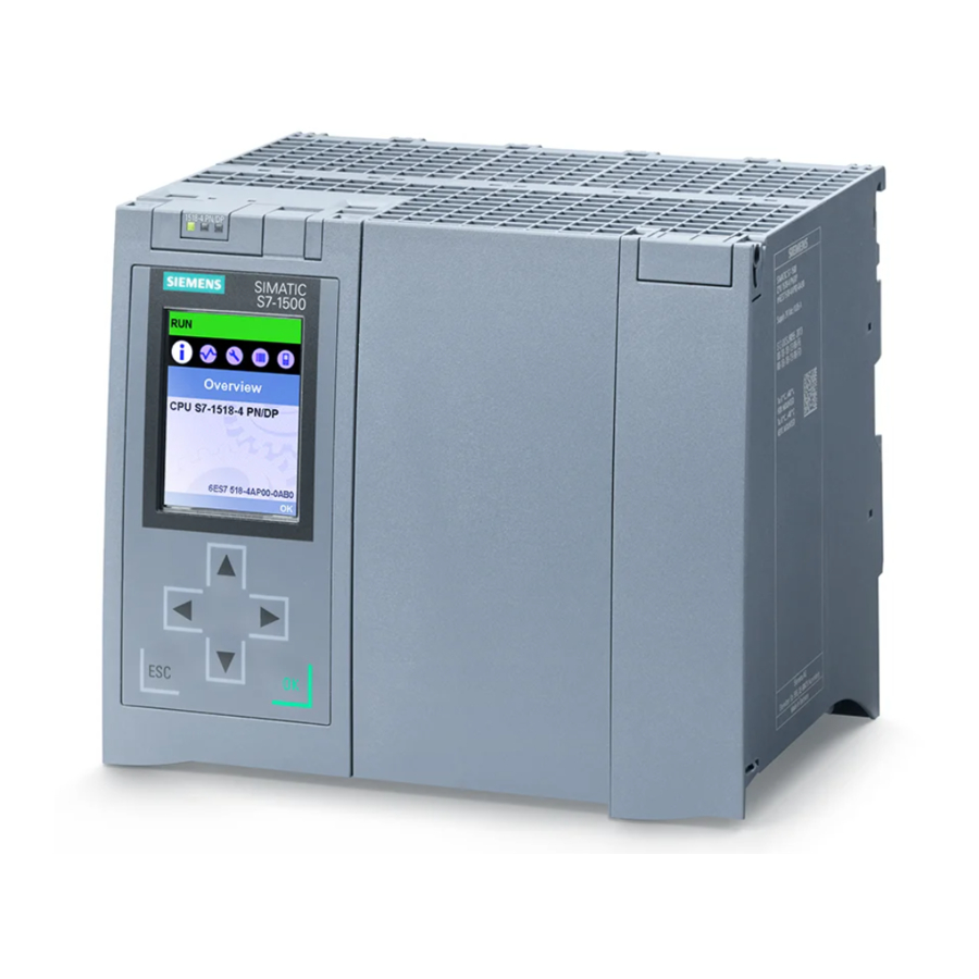
Page 173: Cpu Display
The section below gives an overview of the mode of operation of the CPU display. Detailed information on the individual options, a training course and a simulation of the selectable menu items is available in the SIMATIC S7-1500 Display Simulator (http://www.automation.siemens.com/salesmaterial-as/interactive-manuals/getting- started_simatic-s7-1500/disp_tool/start_en.html). - Page 174 CPU display Display The figures below show an example view of the displays of a CPU 1515-2 PN, CPU 1516-3 PN/DP, CPU 1517-3 PN/DP or CPU 1518-4 PN/DP on the left and a CPU 1511-1 PN or CPU 1513-1 PN on the right. ①...
- Page 175 CPU display ① Regarding : CPU status information The following table shows the CPU status information that can be retrieved via the display. Table 12- 1 CPU status information Color and icons for Meaning the status data Green Orange STOP •...
- Page 176 CPU display ② Regarding : Names of the menus The following table shows the available menus of the display. Table 12- 2 Names of the menus Main menu Meaning Description items Overview The "Overview" menu contains information about the properties of the CPU and the properties of the inserted SIMATIC memory card, as well as information on whether a know-how protection or a linking of the serial number exists.
- Page 177 CPU display Menu icons The following table shows the icons that are displayed in the menus. Table 12- 3 Menu icons Icon Meaning Editable menu item Select the desired language here. There is an alarm in the next lower level object. There is a fault in the next lower level object.
- Page 178 CPU display Handling the front cover The front cover is pluggable. You can remove or replace the front cover during operation (RUN). Removing or replacing the front cover has no effect on the running CPU. To remove the front cover from the CPU, follow these steps: 1.
- Page 179 CPU display Control keys The following keys are available on the CPU's display: ● Four arrow buttons: "up", "down", "left", "right" An automatic scroll function occurs if you hold the arrow button pressed for two seconds ● One ESC key ●...
- Page 180 CPU display Tooltips Some of the values shown on the display (e.g., station name, plant designation, location identifier, PROFINET device name, etc.) can exceed the available display width. This applies in particular to the display of the CPU 1511-1 PN or CPU 1513-1 PN. A tooltip appears when you focus on the respective value on the display and then press the "Left"...
- Page 181 CPU display Uploading image to the display via STEP 7 You can use the "User-defined logo" function under "Display" in the device view of the CPU to load an image from your file system into the display of the CPU via STEP 7. Figure 12-5 Uploading image to CPU To correctly show the aspect ratio of the uploaded image, use the following dimensions...
- Page 182 CPU display Available language settings You can set the following languages separately for menu and alarm texts: ● Chinese ● German ● English ● French ● Italian ● Japanese ● Korean ● Portuguese (Brazil) ● Russian ● Spanish ● Turkish You select the required language directly at the display in the "Display"...
-
Page 183: Maintenance
Maintenance 13.1 Removing and inserting I/O modules Requirement Remove or insert front connectors and I/O modules only when the voltage is switched off. NOTICE Physical damage can occur If you install or uninstall front connectors and/or I/O modules with switched-on voltage, this can lead to undefined conditions in your plant. -
Page 184: Replacement Of I/O Modules And Front Connectors
Maintenance 13.2 Replacement of I/O modules and front connectors 13.2 Replacement of I/O modules and front connectors 13.2.1 Coding element on the I/O module and on the front connector Function All front connectors for the I/O modules of the S7-1500 automation system/ET 200MP distributed I/O system are identical. - Page 185 Maintenance 13.2 Replacement of I/O modules and front connectors Coding element in the front connector When the front connector is inserted into the I/O module for the first time, one half of the coding element latches into the front connector. When you remove the front connector from the I/O module, this half of the coding element remains in the front connector, while the other half remains in the I/O module.
-
Page 186: Replacing An I/O Module
Maintenance 13.2 Replacement of I/O modules and front connectors 13.2.2 Replacing an I/O module Introduction When the front connector is first inserted into the I/O module, a part of the coding element clips onto the front connector. When you replace an I/O module with the same type of module, the correct coding element is already present in the front connector. -
Page 187: Replacing A Front Connector
Maintenance 13.2 Replacement of I/O modules and front connectors 13.2.3 Replacing a front connector Introduction When the front connector is first inserted into the I/O module, a part of the coding element clips onto the front connector. When you replace a defective front connector with a new front connector, then you must transfer the coding element into the new front connector. -
Page 188: Replacing The Coding Element At The Power Connector Of The System Power Supply And Load Current Supply
Maintenance 13.3 Replacing the coding element at the power connector of the system power supply and load current supply 13.3 Replacing the coding element at the power connector of the system power supply and load current supply Introduction The coding consists of a 2-part coding element. Ex factory a part of the coding element is inserted into the back side of the power connector. - Page 189 Maintenance 13.3 Replacing the coding element at the power connector of the system power supply and load current supply Procedure To replace the coding element on the power connector of the system power supply and load current supply, follow these steps: 1.
-
Page 190: Firmware Update
– For the S7-1500 automation system: Automation technology > Automation systems > SIMATIC industrial automation system > Controllers > SIMATIC S7 modular controllers > SIMATIC S7-1500. – For the distributed I/O system ET 200MP: Automation technology > Automation systems > SIMATIC industrial automation systems > SIMATIC ET 200 distributed I/O >... - Page 191 Maintenance 13.4 Firmware update Installation of the firmware update WARNING Impermissible plant states possible The CPU switches to STOP mode or the interface module to "station failure" as a result of the firmware update being installed. STOP or station failure can have an adverse effect on the operation of an online process or a machine.
- Page 192 Procedure using the Web server The procedure is described in the Web server (http://support.automation.siemens.com/WW/view/en/59193560) Function Manual. Special feature at a firmware update of analog modules If you want to carry out a firmware update for analog modules, you have to supply 24 V DC load supply to the module through the power supply element.
-
Page 193: Reset To Factory Settings
Maintenance 13.5 Reset to factory settings 13.5 Reset to factory settings 13.5.1 Resetting the CPU to factory settings Function The CPU can be reset to its factory state using "Reset to factory settings". The function deletes all information that was stored internally on the CPU. Recommendation: If you want to remove a PROFINET CPU and use it elsewhere with a different program, or put it into storage, restore the CPU to the factory state. - Page 194 Maintenance 13.5 Reset to factory settings Perform a reset to factory settings as follows: 1. Set the mode selector to the STOP position. Result: The RUN/STOP LED lights up yellow. 2. Set the mode selector to the MRES position. Hold the mode selector in this position until the RUN/STOP LED lights up for the 2nd time and remains continuously lit (this takes three seconds).
- Page 195 Maintenance 13.5 Reset to factory settings Procedure using STEP 7 To reset a CPU to factory settings via STEP 7, follow these steps: Make sure that there is an online connection to the CPU. 1. Open the Online and Diagnostics view of the CPU. 2.
-
Page 196: Resetting Interface Module (Profinet Io) To Factory Settings
Additional information on "Reset to factory settings" can be found in the Function Manual Structure and use of the CPU memory (http://support.automation.siemens.com/WW/view/en/59193101) in the section on memory areas and retentivity, and in the online help for STEP 7. For information on the memory reset of the CPU, refer to the chapter CPU memory reset (Page 158). - Page 197 Maintenance 13.5 Reset to factory settings Result after resetting to factory settings Table 13- 3 Properties of the interface module when shipped Properties Value Parameter Default setting IP address Not present (can be set when resetting: "Keep IP address"/"Delete IP address") Device name Not present MAC address...
-
Page 198: Test Functions And Fault Resolution
Test functions and fault resolution 14.1 Test functions Introduction You have the option of testing the operation of your user program on the CPU. You can then monitor signal states and values of tags and can assign values to tags to simulate specific situations in the running of the program. - Page 199 Test functions and fault resolution 14.1 Test functions Testing with program status The program status allows you to monitor the execution of the program. You can display the values of operands and the results of logic operations (RLO) allowing you to recognize and fix logical errors in your program.
- Page 200 Test functions and fault resolution 14.1 Test functions Testing with watch tables The following functions are available in the watch table: ● Monitoring of tags You can use the watch tables to monitor the current values of the individual tags of a user program or a CPU on the programming device/PC, on the display of the CPU, and on the web server.
- Page 201 Test functions and fault resolution 14.1 Test functions Testing with a force table The following functions are available in the force table: ● Monitoring of tags You can use the force tables to display the current values of the individual tags of a user program or a CPU on the programming device/PC, on the display of the CPU, and on the web server.
- Page 202 "Traces". With regard to the trace functions, also note the FAQ with the entry ID 102781176 on the Service&Support Internet page (http://www.siemens.com/automation/service&support). Simulation With STEP 7 you can run and test the hardware and software of the project in a simulated environment.
-
Page 203: Reading Out/Saving Service Data
If you have defined your user page as the home page of the Web server, direct access to the service data by inputting the IP address of the CPU is not possible. For more information on reading out service data via a user-defined page, refer to the Web server (http://support.automation.siemens.com/WW/view/en/59193560) function manual. Automation system System Manual, 12/2014, A5E03461182-AC... - Page 204 Test functions and fault resolution 14.2 Reading out/saving service data Procedure using STEP 7 A description of how to save service data is available under the keyword "Save service data" in STEP 7 online help. Procedure via the SIMATIC memory card Use the SIMATIC memory card to read out the service data only if you are no longer able to communicate with the CPU via Ethernet.
-
Page 205: Technical Specifications
Technical specifications Introduction This chapter lists the technical specifications of the system: ● The standards and test values which the modules of the S7-1500 automation system/ET 200MP distributed I/O system comply with and fulfill. ● The test criteria according to which the S7-1500 automation system/ET 200MP distributed I/O system was tested. -
Page 206: Standards And Approvals
Technical specifications 15.1 Standards and Approvals 15.1 Standards and Approvals Currently valid markings and authorizations Note Details on the components of the S7-1500 automation system/ET 200MP distributed I/O system The currently valid markings and approvals are printed on the components of the S7-1500 automation system/ET 200MP distributed I/O system. - Page 207 ● 94/9/EC on "equipment and protective systems for use in hazardous areas" (explosion protection directive) The EC declaration of conformity is held on file available to competent authorities at: Siemens AG Digital Factory Factory Automation DF FA AS DH AMB...
- Page 208 Technical specifications 15.1 Standards and Approvals Installation Instructions for cULus haz.loc. ● WARNING - Explosion Hazard - Do not disconnect while circuit is live unless area is known to be non-hazardous. ● WARNING - Explosion Hazard - Substitution of components may impair suitability for Class I, Division 2 or Zone 2.
- Page 209 Technical specifications 15.1 Standards and Approvals Tick mark for Australia and New Zealand The S7-1500 automation system/ET 200MP distributed I/O system meets the requirements of the standard AS/NZS CISPR 16. Korea Certification KC registration number: KCC-REM-S49-S71500 Please note that this device corresponds to limit value class A in terms of the emission of radio frequency interference.
- Page 210 ● Installation of the S7-1500 automation system/ET 200MP distributed I/O system in grounded control cabinets/control boxes ● Use of noise filters in the supply lines Reference The certificates for the markings and approvals can be found on the Internet under Service&Support (http://www.siemens.com/automation/service&support). Automation system System Manual, 12/2014, A5E03461182-AC...
-
Page 211: Electromagnetic Compatibility
±1 kV (signal lines < 30 m) High-energy single pulse (surge) in accordance with IEC 61000-4-5 External protective circuit required (not for 230 V modules) (see the Defining interference-free controllers (http://support.automation.siemens.com/WW/view/en/59193566) Function Manual) ±2 kV (power supply lines) asymmetric coupling •... - Page 212 Technical specifications 15.2 Electromagnetic compatibility Sinusoidal disturbances The following table shows the electromagnetic compatibility of the S7-1500 automation system/ET 200MP distributed I/O system with regard to sinusoidal disturbances (RF radiation). Table 15- 3 Sinusoidal disturbances with RF radiation RF radiation in accordance with IEC 61000-4-3/NAMUR 21 Corresponds with degree of severity Electromagnetic RF field, amplitude-modulated...
-
Page 213: Shipping And Storage Conditions
Technical specifications 15.3 Shipping and storage conditions Emission of radio interference Interference emission of electromagnetic fields in accordance with EN 55016: Limit value class A, group 1 (measured at a distance of 10 m). Table 15- 5 Interference emission of electromagnetic fields Frequency Interference emission 30 MHz to 230 MHz... -
Page 214: Mechanical And Climatic Ambient Conditions
Technical specifications 15.4 Mechanical and climatic ambient conditions 15.4 Mechanical and climatic ambient conditions Operating conditions The S7-1500 automation system/ET 200MP distributed I/O system is suitable for use in weather-proof, fixed locations. The operating conditions exceed requirements according to DIN IEC 60721-3-3: ●... -
Page 215: Information On Insulation Tests, Protection Class, Degree Of Protection And Rated Voltage
Technical specifications 15.5 Information on insulation tests, protection class, degree of protection and rated voltage Climatic ambient conditions The following table shows the permissible climatic ambient conditions for the S7-1500 automation system/ET 200MP distributed I/O system: Table 15- 9 Climatic ambient conditions Ambient conditions Permissible range Comments... -
Page 216: Use Of The S7-1500/Et 200Mp In Zone 2 Hazardous Areas
Static value: Creation as functional extra-low voltage with safe galvanic isolation according to IEC 60364-4-41. 15.6 Use of the S7-1500/ET 200MP in zone 2 hazardous areas Reference See product information Deployment of the modules in zone 2 hazardous atmospheres (http://support.automation.siemens.com/WW/view/en/19692172). Automation system System Manual, 12/2014, A5E03461182-AC... -
Page 217: Dimension Drawings
Dimension drawings Dimension drawings of the mounting rails Mounting rail 160 mm Figure A-1 Mounting rail 160 mm Automation system System Manual, 12/2014, A5E03461182-AC... - Page 218 Dimension drawings A.1 Dimension drawings of the mounting rails Mounting rail 245 mm Figure A-2 Mounting rail 245 mm Mounting rail 482.6 mm Figure A-3 Mounting rail 482.6 mm Automation system System Manual, 12/2014, A5E03461182-AC...
- Page 219 Dimension drawings A.1 Dimension drawings of the mounting rails Mounting rail 530 mm Figure A-4 Mounting rail 530 mm Mounting rail 830 mm Figure A-5 Mounting rail 830 mm Automation system System Manual, 12/2014, A5E03461182-AC...
-
Page 220: Dimension Drawing Of Shielding Bracket For 35 Mm Modules
Dimension drawings A.2 Dimension drawing of shielding bracket for 35 mm modules Mounting rail 2000 mm Figure A-6 Mounting rail 2000 mm Dimension drawing of shielding bracket for 35 mm modules Figure A-7 Dimension drawing of shielding bracket for 35 mm modules Automation system System Manual, 12/2014, A5E03461182-AC... -
Page 221: Dimension Drawing Of Shielding Bracket For 25 Mm Modules
Dimension drawings A.3 Dimension drawing of shielding bracket for 25 mm modules Dimension drawing of shielding bracket for 25 mm modules Figure A-8 Dimension drawing of shielding bracket for 25 mm modules Dimension drawing of shielding bracket for 35 mm modules Figure A-9 Dimension drawing of shielding bracket for 35 mm modules Automation system... -
Page 222: Dimension Drawing Of Shielding Bracket For 25 Mm Modules
Dimension drawings A.5 Dimension drawing of shielding bracket for 25 mm modules Dimension drawing of shielding bracket for 25 mm modules Figure A-10 Dimension drawing of shielding bracket for 25 mm modules Dimension drawing of shielding bracket for 35 mm modules Figure A-11 Dimension drawing of shielding bracket for 35 mm modules Dimension drawing of shielding bracket for 25 mm modules... -
Page 223: Dimension Drawings Of The Labeling Strips
Dimension drawings A.8 Dimension drawings of the labeling strips Dimension drawings of the labeling strips Figure A-13 Dimension drawing labeling strips for 35 mm modules Figure A-14 Dimension drawing labeling strips for 25 mm modules Automation system System Manual, 12/2014, A5E03461182-AC... -
Page 224: Accessories/Spare Parts
Accessories/spare parts Accessories for the S7-1500 automation system/ET 200MP distributed I/O system Table B- 1 General accessories Description Part number Mounting rail 6ES7590-1AB60-0AA0 Mounting rail, 160 mm (with drill holes) • 6ES7590-1AC40-0AA0 Mounting rail, 245 mm (with drill holes) • 6ES7590-1AE80-0AA0 Mounting rail, 482 mm (with drill holes) •... - Page 225 Accessories/spare parts Description Part number Power cable connector with coding element for power supplies 6ES7590-8AA00-0AA0 (spare part), 10 units Potential bridge for front connector (spare part), 20 units 6ES7592-3AA00-0AA0 Universal front cover for 35 mm I/O modules (spare part), 5 units 6ES7528-0AA00-7AA0 Consists of: 5 x front cover...
- Page 226 Accessories/spare parts Online catalog Other article numbers for the S7-1500 automation system/ET 200MP distributed I/O system can be found on the Internet (https://mall.industry.siemens.com) in the online catalog and the online order system. Automation system System Manual, 12/2014, A5E03461182-AC...
-
Page 227: Service & Support
Our Service & Support accompanies you worldwide in all matters concerning automation and drive technology from Siemens. We provide direct on-site support in more than 100 countries through all phases of the life cycle of your machines and plants. - Page 228 The comprehensive online information platform supports you in all aspects of our Service & Support at any time and from any location in the world. You can find Online Support on the Internet at the following address: Internet (http://www.siemens.com/automation/service&support). Technical Consulting Support in planning and designing your project: From detailed actual-state analysis, definition of the goal and consultation on product and system questions right through to the creation of the automation solution.
- Page 229 At your service locally, around the globe: your partner for consultation, sales, training, service, support, spare parts... for the entire range of products supplied by Industry Automation and Drive Technologies. You can find your personal contact in our contacts database at: Internet (http://www.siemens.com/automation/partner). Automation system System Manual, 12/2014, A5E03461182-AC...
-
Page 230: Glossary
Glossary Actuator Actuators can be power relays or contactors for switching on loads, or they can be loads themselves (e.g., directly controlled solenoid valves). Automation system Programmable logic controller for the closed-loop and open-loop control of process chains in the process engineering industry and manufacturing technology. The automation system consists of different components and integrated system functions according to the automation task. - Page 231 Glossary The CPU uses the integrated system power supply to supply the electronics of the modules via the backplane bus. The CPU contains the operating system and executes the user program. The user program is located on the SIMATIC memory card and is processed in the work memory of the CPU.
- Page 232 Glossary F-CPU An F-CPU is a central processing unit with fail-safe capability that is permitted for use in SIMATIC Safety. A standard user program can also be run on the F-CPU. Firmware update Updating the firmware of modules (interface modules, I/O modules, etc.), for example after functional expansions, to the latest firmware version (update).
- Page 233 Glossary Interface module Module in the distributed I/O system. The interface module connects the distributed I/O system to the CPU (IO controller) via a fieldbus, and prepares the data for and from I/O modules. Isolated modules In the case of isolated input/output modules, the reference potentials of the control and load circuits are galvanically isolated, e.g.
- Page 234 Glossary Process image (I/O) The CPU transfers the values from the input and output modules in this memory area. At the start of the cyclic program the signal states of the input modules are transmitted to the process image of the inputs. At the end of the cyclic program the process image of the outputs is transmitted as signal state to the output modules.
- Page 235 Glossary PROFINET IO device Distributed field device that can be assigned to one or more IO controllers (e.g. distributed I/O system, valve terminals, frequency converters, switches). Push-in terminal Terminal for the tool-free connection of wires. Reference potential Potential from which the voltages of the circuits involved are observed and/or measured. Restart During a restart (warm restart), all non-retentive bit memory is deleted and non-retentive DB contents are reset to the initial values from load memory.
- Page 236 Glossary Switch PROFIBUS is a linear network. The communication nodes are linked by means of a passive cable - the bus. By contrast, Industrial Ethernet consists of point-to-point connections: each communication node is interconnected directly with precisely one other communication node. If a communication node is linked to several communication nodes, this communication node is connected to the port of an active network component - the switch.
- Page 237 Glossary Warm restart See "Restart" Automation system System Manual, 12/2014, A5E03461182-AC...
-
Page 238: Index
Index Components Overview of the ET 200MP, 19 Configuration, 53 Basics, 81 24 V DC supply, 52 Electrical, 56 ET 200MP, 17 On grounded reference potential, 53 Configuration control, 123, 124 Accessories, 224 Configuration control for IO systems, 123 Addressing, 84 Configuring, 105 Analog modules, 88 Properties of the CPUs, 83... - Page 239 Index Installing, uninstalling, 50 Marking, 77 Electromagnetic compatibility (EMC), 211 replacing, 186 Electrostatic discharge, 211 Identification data, 161 EMC (Electromagnetic compatibility), 211 Record structure, 164 Disturbances, 211 IEC 60204, 51 Radio interference, 213 IEC 61131, 209 EMERGENCY-STOP devices, 51 Infeed, 53 ET 200MP, 16 Infeed, grounded, 53 Accessories, 224...
- Page 240 Index Reset to factory settings, 193 Test functions, 198 PE connection element, 19 Marking, 77, 78 PELV, 53 Labeling strips, 77 Pollution degree, 215 optional, 78 Potential bridge, 20 Maximum configuration Front connectors, 65 with PROFIBUS interface module, 26 Power balance calculation, 34 with PROFINET interface module, 25 Overload, 35 Memory reset...
- Page 241 Index Shielding bracket, 21, 220, 220, 221 General rules for the S7-1500 CPU/the ET 200MP Shipping conditions, 213 interface module, 51 Short-circuit and overload protection, 54 Front connectors, (Analog modules), 71 SIMATIC memory card, 167, 171, 172 Front connectors, (Analog modules), 71 Basics, 167 Load current supply, 62 Firmware card, 171...