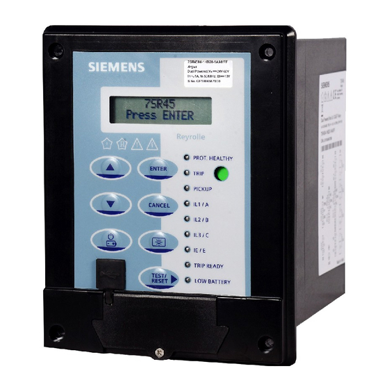
Siemens 7SR45 Argus User Manual
Self powered/dual powered non-directional overcurrent and earth fault relay
Hide thumbs
Also See for 7SR45 Argus:
- Device manual (118 pages) ,
- Manual (102 pages) ,
- User manual (68 pages)

Related Manuals for Siemens 7SR45 Argus


Summary of Contents for Siemens 7SR45 Argus
- Page 1 Reyrolle Protection Devices 7SR45 Argus Self Powered/Dual Powered Non-Directional Overcurrent and Earth Fault Relay...
- Page 2 © 2018 Siemens Protection Devices Limited...
- Page 3 Limited. No part of this document shall be reproduced or modified or stored in another form, in any data retrieval system, without the permission of Siemens Protection Devices Limited, nor shall any model or article be reproduced from this document unless Siemens Protection Devices Limited consent.
-
Page 4: Description Of Operation
Limited. No part of this document shall be reproduced or modified or stored in another form, in any data retrieval system, without the permission of Siemens Protection Devices Limited, nor shall any model or article be reproduced from this document unless Siemens Protection Devices Limited consent. -
Page 5: Table Of Contents
3.13.1 BO Trip/Reset on Battery/USB .................... 40 3.13.2 BO Trip/Reset on CT Input or Auxiliary Voltage ..............40 3.14 Pulse Output ........................... 41 3.15 Remote Flag Output ........................41 ©2018 Siemens Protection Devices Limited Chapter 1 Page 2 of 48... - Page 6 Figure 2-2 7SR45 Argus Relay Front Fascia without Flag Output................ 14 Figure 2-3 7SR45 Argus Relay Connectors with 4 BI and 4 BO ................15 Figure 2-4 7SR45 Argus Relay Connectors with 2 BI and 2 BO ................16 Figure 2-5 7SR4501/7SR4502/7SR4503 Argus Self Powered Relay LED Indication Label ........
-
Page 7: Siemens Protection Devices Limited
The following notational and formatting conventions are used within the remainder of this document: • Setting Menu Location MAIN MENU>SUB-MENU • Setting: Elem name -Setting • Setting value: value • Alternatives: [1st] [2nd] [3rd] ©2018 Siemens Protection Devices Limited Chapter 1 Page 4 of 48... - Page 8 7SR45 Argus Relay is “not in the battery power mode” and paper strip is inserted between the battery clip and battery. The lithium metal cells for 7SR45 Argus Relay (as a spare part) are also subject to the special provision (SP)188 mentioned above, but classified according to: ...
-
Page 9: Open Source Software
Source Software is licensed royalty-free. Insofar as the applicable Open Source Software License Conditions provide for it you can order the source code of the Open Source Software from your Siemens sales contact - against payment of the shipping and handling charges - for a period of at least 3 years since purchase of the Product. -
Page 10: Section 1: Introduction
7SR45 Argus is a member of Siemens Reyrolle protection devices Argus product family. 7SR45 Argus Self Powered/Dual Powered Non-Directional Overcurrent and Earth Fault Relay is housed in a 4U high, size 4 non draw-out case and provides protection, monitoring, and instrumentation functions with integrated input and output logic and fault reports. -
Page 11: Ordering Options
51G/51N Time delayed earth fault 50LC/SOTF Switch-On-To-Fault Additional functionality No additional functionality 4CT is configured as 3PF + EF Use the following ordering information to order 7SR45 Argus Relay battery spares. Table 1-1 Battery Spares Ordering Options Variants Description 7XG1900-1AA00-0AA0... -
Page 12: Functional Diagram
Chapter 1 - 7SR45 Description of Operation Functional Diagram 7SR45 50LC/ SOTF (x2) 50LC/ SOTF (x2) 50LC/ SOTF (x2) (x2) (x2) Figure 1-1 Functional Diagram of 7SR45 Argus Relay ©2018 Siemens Protection Devices Limited Chapter 1 Page 9 of 48... -
Page 13: Terminal Diagram
Chapter 1 - 7SR45 Description of Operation Terminal Diagram The 7SR45 Argus Relay is housed in a non draw-out 4U size 4 case. The rear connection comprises of user-friendly pluggable type terminals: • Binary Input (BI) • Binary Output (BO) •... -
Page 14: Figure 1-3 Terminal Diagram Of Self Powered (7Sr4501-Xgb10-1Aa0) And
- ve + ve - ve NOTES: Items shown in BOLD are ordering options Figure 1-4 Terminal Diagram of Dual Powered (7SR4501/7SR4503-x[H/J]B10-1AA0) Non-Directional Overcurrent and Earth Fault Relay with Flag ©2018 Siemens Protection Devices Limited Chapter 1 Page 11 of 48... -
Page 15: Figure 1-5 Terminal Diagram Of Dual Powered (7Sr4502/7Sr4504) Non-Directional Overcurrent And Earth Fault Relay With Flag
Terminal Diagram of Dual Powered (7SR4502/7SR4504) Non-Directional Overcurrent and Earth Fault Relay with Flag The CT terminals are suitable for ring type lug connection and to provide a secure and reliable termination. ©2018 Siemens Protection Devices Limited Chapter 1 Page 12 of 48... -
Page 16: Section 2: Hardware Description
Section 2: Hardware Description General The structure of the 7SR45 Argus relay is based on the compact hardware platform. The 7SR45 Argus relay is supplied in a non draw-out 4U high size 4 case. The hardware design provides a commonality between the products and components across the range of relays. -
Page 17: Front Fascia Without Flag Output
For AC connections, the auxiliary supply is made with the live connection to positive terminal and neutral connection to negative for consistency and safety. If the power supply voltage levels are falling below the relay minimum operate level, the 7SR45 Argus relay power will automatically switch over to CT power through phase CT currents. -
Page 18: Connectors
Chapter 1 - 7SR45 Description of Operation Connectors In 7SR45 Argus Relay, all the connectors are pluggable type except the CT connectors. The relay consists of the following connectors and the connector terminals are designated suitably: • Auxiliary power supply •... -
Page 19: Operator Interface
The operator interface is designed to provide a user-friendly method of entering the settings and retrieving data from the relay. The rating label is located on the housing and provides more technical information about the 7SR45 Argus Relay. Figure 2-5 7SR4501/7SR4502/7SR4503 Argus Self Powered Relay LED Indication Label ©2018 Siemens Protection Devices Limited... -
Page 20: Relay Information
MLFB ordering code, with hardware version suffix • Serial number Where, GF – Goa factory YY – Year of manufacturing MM – Month of manufacturing XXXXXX – Serial number of the relay ©2018 Siemens Protection Devices Limited Chapter 1 Page 17 of 48... -
Page 21: Liquid Crystal Display (Lcd)
Each general alarm will also generate an event. The backlight TURNS ON automatically if the 7SR45 Argus Relay is powered on with phase CT input and the current is more than 0.4xI (single phase) or 0.14xI... -
Page 22: Keypad
2.6.2 Keypad The 7SR45 Argus Relay keypad consists of 5 standard keys for navigation and for editing the values. The standard keys are used to navigate the menu structure and configure the relay functions. The 2 additional keys are available for LCD backlight and battery mode. -
Page 23: Light Emitting Diode (Led)
Chapter 1 - 7SR45 Description of Operation 2.6.3 Light Emitting Diode (LED) 2.6.3.1 Indication The 7SR45 Argus relay consists of 9 non-programmable LEDs. LED indicates the operating status of the relay such as TRIP READY and PICKUP. The pre-defined LED functions are: Table 2-1 LED Functions... -
Page 24: Home Screen
Chapter 1 - 7SR45 Description of Operation Home Screen After the 7SR45 Argus relay is powered on, the user can access or navigate to other menus from the Home Screen. The following operations can be performed from the home screen: ENTER Press ENTER key to navigate to SETTING MODE. -
Page 25: Alert Screen
This alert appears when the relay is powered by phase CT. This alert appears when the relay is powered by auxiliary power supply. ©2018 Siemens Protection Devices Limited Chapter 1 Page 22 of 48... -
Page 26: Parameter Edit Screen
Chapter 1 - 7SR45 Description of Operation 2.11 Parameter Edit Screen 7SR45 Argus Relay allows the user to edit the parameter value in the LCD. To edit any parameter, follow the procedure: From the Relay Identifier screen, navigate to the Parameter screen. -
Page 27: Instantaneous Overcurrent Protection (50)
Section 3: Protection Functions (50, 51, 50N, 51N, 50G, 51G, 50LC) Instantaneous Overcurrent Protection (50) Two Instantaneous overcurrent elements are provided in the 7SR45 Argus Relay. 50-1, 50-2 Each instantaneous element (50-n) has independent settings. 50-n Setting for pick-up current and 50-n Delay definite time delay. -
Page 28: Time Delayed Overcurrent Protection (51)
Chapter 1 - 7SR45 Description of Operation Time Delayed Overcurrent Protection (51) One time delayed overcurrent element is provided in the 7SR45 Argus Relay. 51-1 51-n Setting sets the pick-up current level. A total of 7 shaped characteristics are provided from IEC and ANSI standards. An inverse definite minimum time (IDMT) characteristic is selected using 51-n Char. - Page 29 0.01 for DTL) Gn 51-n Min Minimum Operate 20 s 0.01 Operate Time Gn 51-n Follower Follower DTL 20 s 0.01 60, IEC/ Gn 51-n Reset Reset ANSI DECAY ©2018 Siemens Protection Devices Limited Chapter 1 Page 26 of 48...
-
Page 30: Instantaneous Derived Earth Fault Protection (50N)
Chapter 1 - 7SR45 Description of Operation Instantaneous Derived Earth Fault Protection (50N) Two instantaneous derived earth fault elements are provided in the 7SR45 Argus Relay. 50N-1, 50N-2 Earth current is derived by calculating the vector sum of the measured phase currents. -
Page 31: Time Delayed Derived Earth Fault Protection (51N)
Chapter 1 - 7SR45 Description of Operation Time Delayed Derived Earth Fault Protection (51N) One time delayed derived earth fault element is provided in the 7SR45 Argus Relay. 51N-1 51N-n Setting sets the pick-up current level. A total of 7 shaped characteristics are provided from IEC and ANSI. An inverse definite minimum time (IDMT) characteristic is selected using 51N-n Char. - Page 32 0.01 DTL) Gn 51N-n Min Minimum Operate 20 s 0.01 Operate Time Gn 51N-n Follower DTL 20 s 0.01 Follower DTL 60, IEC/ Gn 51N-n Reset Reset ANSI DECAY ©2018 Siemens Protection Devices Limited Chapter 1 Page 29 of 48...
-
Page 33: Instantaneous Measured Earth Fault Protection (50G)
Instantaneous Measured Earth Fault Protection (50G) The earth current is measured directly via a dedicated current analogue input, IL4/I Two instantaneous measured earth fault elements are provided in the 7SR45 Argus Relay. 50G-1, 50G-2 Each instantaneous element has independent settings for pick-up current 50G-n Setting and a definite time delay 50G-n Delay. -
Page 34: Time Delayed Measured Earth Fault Protection (51G)
Chapter 1 - 7SR45 Description of Operation Time Delayed Measured Earth Fault Protection (51G) One time delayed measured earth fault element is provided in the 7SR45 Argus Relay. 51G-1 51G-n Setting sets the pick-up current level. A total of 7 shaped characteristics are provided from IEC and ANSI. An inverse definite minimum time (IDMT) characteristic is selected using 51G-n Char. - Page 35 DTL) Gn 51G-n Min Minimum Operate 20 s 0.01 Operate Time Gn 51G-n Follower DTL 20 s 0.01 Follower DTL 60, IEC/ Gn 51G-n Reset Reset ANSI 0.01 DECAY ©2018 Siemens Protection Devices Limited Chapter 1 Page 32 of 48...
-
Page 36: Switch-On-To-Fault (50Lc/Sotf)
Gn 50 LC / SOTF Measurement 25 AC cycles Figure 3-7 Logic Diagram: 50LC Overcurrent Element Table 3-10 50LC/SOTF Parameters Description Default Value Step Change Gn 50LC/SOTF Pick-up current 20xI Setting ©2018 Siemens Protection Devices Limited Chapter 1 Page 33 of 48... -
Page 37: Figure 3-8 Operating Time For Switch-On-To Fault With Binary Outputs
NOTE: The multi-phase faults results to a shorter operating time. Under the low battery or battery drained condition, the boot up time is increased by maximum of 25 ms. ©2018 Siemens Protection Devices Limited Chapter 1 Page 34 of 48... -
Page 38: General Alarm
In the CT power mode, LED test can be performed if the current is more than 0.4xIn (single phase) or 0.14xIn (three phase). If the fault current persists, pop-up message appears on the LCD “FAULT PERSISTS”. ©2018 Siemens Protection Devices Limited Chapter 1 Page 35 of 48... -
Page 39: Reset Through Binary Input
From the Relay Identifier Screen, reset the LEDs and outputs by pressing the TEST/RESET► key. 3.9.4 Reset through rear communication protocol The resetting of LEDs and BOs can be possible via the rear communication protocol like Modbus and IEC 60870-5-103. ©2018 Siemens Protection Devices Limited Chapter 1 Page 36 of 48... -
Page 40: Current Inputs
The status of BI can be viewed via LCD or Reydisp Evolution software or SCADA. The 7SR45 Argus Relays are available with 2 or 4 binary inputs. The user can assign any binary input to any of the available functions such as inhibits, binary outputs, reset flags, and general alarms (INPUT CONFIG > INPUT MATRIX). - Page 41 NOTE: When any binary input is assigned to Trip Pulse Output and when the TEST/RESET key is pressed, a “FAULT/ MAINT PERSISTS” pop up appears. ©2018 Siemens Protection Devices Limited Chapter 1 Page 38 of 48...
-
Page 42: Binary Outputs
Chapter 1 - 7SR45 Description of Operation 3.12 Binary Outputs The 7SR45 Argus Relay consists of 2 or 4 binary output which can be configured to send commands to the switchgear units and annunciations for remote signalling of the important events and status. -
Page 43: Binary Output Operations
HMI “INSUFFICIENT ENERGY”. 3.13.2 BO Trip/Reset on CT Input or Auxiliary Voltage In this mode, the relay can operate/reset the binary outputs instantaneously. ©2018 Siemens Protection Devices Limited Chapter 1 Page 40 of 48... -
Page 44: Pulse Output
• Battery The 7SR45 Argus Relay is powered primarily from auxiliary voltage even if all other power sources are available. In the absence of auxiliary voltage, the relay is powered through phase currents. In the absence of both auxiliary voltage and phase currents, the relay can be powered on by USB or battery. -
Page 45: Figure 3-14 Sensitivity For Single Phase Fault With Binary Output
Chapter 1 - 7SR45 Description of Operation The sensitivity of 7SR45 Argus Relay is 0.20xIn (minimum phase current) in single phase or 0.10xIn (minimum phase current) in three phase. This minimum phase current is necessary for the healthy functioning of the relay. -
Page 46: Usb
In the battery mode, the relay can be energized by pressing the BAT ON/OFF key or if any binary input status is changed. The battery is used to operate 7SR45 Argus Relay only when other power sources are not available. In the battery mode, all the settings can be edited even if the protection functions are inactive. The binary inputs and binary outputs are operational in the battery mode. -
Page 47: Sleep Mode
3.16.5 Sleep Mode The 7SR45 Argus Relay goes to the sleep mode when the auxiliary power/CT power and USB power are not available. When the relay is in sleep mode, the user can access the LCD by pressing the BAT ON/OFF key. -
Page 48: Data Storage
Setting Error The 7SR45 Argus Relay checks for the integrity of the settings during the start up and displays a message in case of an error and IRF condition will be signalled. -
Page 49: Event Records (Event Log)
When the user presses ENTER after editing the seconds, seconds is set to zero and the clock starts. By default, the clock follows a 24 hour format for time and DD/MM/YYYY format for date. 3.21 Operating Mode The 7SR45 Argus relay has the three operating modes: • Local •... -
Page 50: Settings Groups
Passwords can be de-activated by using the password to gain access and by entering the password NONE. Again this must be entered twice to deactivate the security system. ©2018 Siemens Protection Devices Limited Chapter 1 Page 47 of 48... -
Page 51: Battery
Siemens customer support representatives and the password can be retrieved. 3.24 Battery 7SR45 Argus Relay consists of CR123 A, 3 V 1400 mAh Li-Mn non rechargeable battery. The battery is used to energize the device when auxiliary voltage/phase current/USB is not available. The user can perform actions such as viewing the fault records, setting change, and resetting the flags with battery power. - Page 52 This document is issue 2018/06. The list of revisions up to and including this issue is: 2018/06 Seventh Issue 2018/04 Sixth Issue 2017/08 Fifth Issue 2017/01 Fourth Issue 2016/10 Third Issue 2016/09 Second Issue 2015/08 First Issue © 2018 Siemens Protection Devices Limited...
- Page 53 Figure 1-3 Menu Structure..........................5 Figure 2-1 USB connection to PC ........................7 Figure 2-2 RS485 connection to PC ......................7 Figure 2-3 PC Com Port Selection ......................... 9 © 2018 Siemens Protection Devices Limited Chapter 2 Page 2 of 9...
-
Page 54: Section 1: Introduction
TEST/RESET► key. Press ▲ or ▼ keys to scroll through the first and last settings. If the keys are pressed further from the first and last settings sub menu, it exits from the sub menu and returns to the previous menu. © 2018 Siemens Protection Devices Limited Chapter 2 Page 3 of 9... -
Page 55: Instrument Mode
For more information about IRF, refer to Chapter 1, IRF table. BATTERY PROFILE The battery profile meter displays the status of the operations performed on the battery power. © 2018 Siemens Protection Devices Limited Chapter 2 Page 4 of 9... - Page 56 DATA STORAGE Clr Battery Data Output Test MAINTENANCE * Available for 7SR45 Argus Dual Powered Relay # For 7SR4501-xGA10-1AA0 variant, the multiple settings group and relay modes are not available. Figure 1-3 Menu Structure © 2018 Siemens Protection Devices Limited...
-
Page 57: Fault Data Mode
Chapter 2 - 7SR45 Settings & Instrument Guide Fault Data Mode 7SR45 Argus Relay stores maximum of 10 fault records. Each stored fault data can be viewed by pressing the TEST/RESET► key. Each record contains data of the operated elements, analogue values, and LED status at the time of the fault. -
Page 58: Section 2: Setting & Configuring The Relay Using Reydisp Evolution
RS485 Screened RS232 straight Laptop computer Rear terminals twisted pair through cable or USB to RS232 25 pin male D Converter cable connector Figure 2-2 RS485 connection to PC © 2018 Siemens Protection Devices Limited Chapter 2 Page 7 of 9... -
Page 59: Configuring Relay Serial Data Communication
2.1.3 Configuring Relay Serial Data Communication This section is applicable for configuring the 7SR45 Argus Dual Powered Relay. Using the keys on the relay fascia scroll down the settings menus into the ‘communications’ menu and if necessary change the settings for the communication port you are using on the relay. Reydisp software uses IEC60870-5-103 protocol to communicate. -
Page 60: Connecting To The Relay For Setting Via Reydisp
In Reydisp Evolution, check that the Relay Address is set as “1” in the Relay menu. (this is for 7SR450[1/3]-xGx10-1AA0) In Reydisp Evolution, check that the Relay Address in the Relay menu is same as that of the Device address.(for 7SR450[1/2/3/4]-[1/2][G/H/J][A/B][1/2]0-1AA0). © 2018 Siemens Protection Devices Limited Chapter 2 Page 9 of 9... - Page 61 This document is issue 2018/06. The list of revisions up to and including this issue is: 2018/06 Seventh Issue 2018/04 Sixth Issue 2017/08 Fifth Issue 2017/01 Fourth Issue 2016/10 Third Issue 2016/09 Second Issue 2015/08 First Issue © 2018 Siemens Protection Devices Limited...
- Page 62 Chapter 3 - 7SR45 Performance Specification Contents Section 1: Performance Specification ......................... 3 1.1 Indication of Conformity ........................3 1.2 Technical Specifications ........................3 1.3 Environmental Performance ......................7 1.4 Performance Specification ....................... 13 ©2018 Siemens Protection Devices Limited Chapter 3 Page 2 of 14...
-
Page 63: Section 1: Performance Specification
(Low Voltage Directive 2014/35/EU) as well as restriction on usage of hazardous substances in electrical and electronic equipment (RoHS Directive 2011/65/EU). This conformity has been proved by tests conducted by Siemens AG in accordance of the Council Directive in accordance with the product standard IEC/EN 60255-26 for the EMC directives, and with the standard IEC/EN 60255-27 for the low-voltage directive. - Page 64 < 12 VA consumption (AC) ≤ 20 ms (19.2 V DC) Max Interruption time (Collapse to Zero) ≤ 20 ms (48 V DC) ≤ 500 ms (230 V AC) ©2018 Siemens Protection Devices Limited Chapter 3 Page 4 of 14...
- Page 65 250 VA at p.f. ≤0.4 DC Resistive 75 W DC Inductive 30 W at L/R ≤40 ms 50 W at L/R ≤10 ms Electrical Endurance 10000 operations, 250 A, 5 A AC Disengaging time < 20 ms © 2018 Siemens Protection Devices Limited...
- Page 66 Protocol Support Modbus RTU, IEC 60870-5-103 Data Transfer rate: Rate 1200 bps to 57600 bps Table 1-11 Data Storage Fault Record 10 records Events 100 events (1 ms resolution) ©2018 Siemens Protection Devices Limited Chapter 3 Page 6 of 14...
-
Page 67: Environmental Performance
Chapter 3 - 7SR45 Performance Specification Environmental Performance This section describes about the environmental tests performed with 7SR45 Argus Relay under different conditions. Table 1-12 Mechanical Tests Type Test Reference Requirement Degree of Protection IEC 60529 IP52 front IP20 rear... - Page 68 30 MHz – 230 MHz, 40 dB µ V/m (quasi peak) 230 MHz – 1 GHz, 47 dB µ V/m (quasi peak) Limits are measured at 10 m distance ©2018 Siemens Protection Devices Limited Chapter 3 Page 8 of 14...
- Page 69 RV = 110 V DC 40 % RV for 0.2 s Normal Operation 70 % RV for 0.5 s Normal Operation DC Voltage Dips IEC 60255-26 0 % RV for 0.02 s Normal Operation © 2018 Siemens Protection Devices Limited...
- Page 70 +25…55°C, R.H. > 93 % RH (6 cycles) IEC 60255-1 At lower temperature, 97 %, -2 % +3 % RH At upper temperature, 93 %, ± 3 % RH ©2018 Siemens Protection Devices Limited Chapter 3 Page 10 of 14...
- Page 71 Terminals Class UL 94 V-0 Terminal Mounting Class UL 94 V-0 Wiring (CT) (N)2GFAF (VDE) Components mounting Class UL 94 V-0 Enclosure Class UL 94 V-0 Class UL 94 V-0 Class UL 94 V-0 © 2018 Siemens Protection Devices Limited...
- Page 72 Simulated Inrush current with 15 % 2 harmonic content Test Result The immunity against inrush currents is up to 3 times of the peak value with 95 % fundamental current (I ©2018 Siemens Protection Devices Limited Chapter 3 Page 12 of 14...
-
Page 73: Performance Specification
Binary Input NOTE: Add current tolerance of ± 5 % or ± 2 %xI (whichever is greater) to the operating time tolerance for TMS below 0.1 and I below 0.1. ©2018 Siemens Protection Devices Chapter 3 Page 13 of 14... - Page 74 Operate level 100 % I , ± 5 % Disengaging time < 50 ms For more information about 50LC/SOTF, refer to Chapter 1 - 7SR45 Description of Operation, Switch-On-To-Fault ©2018 Siemens Protection Devices Limited Chapter 3 Page 14 of 14...
- Page 75 This document is issue 2018/06. The list of revisions up to and including this issue is: 2018/06 Seventh Issue 2018/04 Sixth Issue 2017/08 Fifth Issue 2017/01 Fourth Issue 2016/10 Third Issue 2016/09 Second Issue 2015/08 First Issue © 2018 Siemens Protection Devices Limited Chapter 4 Page 1 of 20...
- Page 76 EVENT ..........................13 5.2.6 EVENTCOUNT ........................14 5.2.7 TIME_METER ........................14 5.2.8 STR32 and STR64 ......................15 5.2.9 POINTS LIST ........................15 Appendix 1 ..............................19 Appendix 2 ..............................20 © 2018 Siemens Protection Devices Limited Chapter 4 Page 2 of 20...
-
Page 77: Section 1: Introduction
Downloads.aspx. This section specifies connection details and lists the information available through the individual protocols. NOTE: The 7SR45 Argus Dual Powered Relay variant only supports the data communication. © 2018 Siemens Protection Devices Limited Chapter 4 Page 3 of 20... -
Page 78: Section 2: Physical Connection
Addr to identify the relay. Each relay in a network must have a unique address. USB Mode Local Local or Remote Local or Remote Remote © 2018 Siemens Protection Devices Limited Chapter 4 Page 4 of 20... -
Page 79: Rs485 Interface
Station 1 to 247 for Modbus RTU protocol must be given to identify the Address relay. Each relay in a network must have a unique address. © 2018 Siemens Protection Devices Limited Chapter 4 Page 5 of 20... - Page 80 Include line To Control terminating Res System Rear terminals Rear terminals RS485 Screened RS485 Screened twisted pair twisted pair Figure 2-2 Communication to Multiple Devices using RS485 (Standard Port) © 2018 Siemens Protection Devices Limited Chapter 4 Page 6 of 20...
-
Page 81: Section 3: Glossary
Bit (logical 0) sent to signify the start of a byte during data transmission. Stop Bit Bit (logical 1) sent to signify the end. Universal Serial Bus standard for the transfer of data. © 2018 Siemens Protection Devices Limited Chapter 4 Page 7 of 20... -
Page 82: Section 4: Iec 60870-5-103 Definitions
4.2.2 Point List The following sub-sections contain tables listing the data points available via the IEC60870-5-103 protocol. Note that not all events are available on all relay models. © 2018 Siemens Protection Devices Limited Chapter 4 Page 8 of 20... -
Page 83: Event Function (Fun) & Information (Inf) Numbers
LED 5 LED 6 LED 7 LED 8 LED 9 Reset FCB Reset CU Start/Restart Power On SE, GI LEDs reset (Reset Flag & Outputs) Ack, Nak Settings changed © 2018 Siemens Protection Devices Limited Chapter 4 Page 9 of 20... - Page 84 End of GI End of GI NOTE: * For 7SR4501 Dual Powered Relay variant, these parameters are not available. NOTE: For the list of events raised, refer to Appendix © 2018 Siemens Protection Devices Limited Chapter 4 Page 10 of 20...
-
Page 85: Measurands
This t3.5 delay needs to be provided by the IEC103 master for response to another query. 7SR45 Argus Relay follows the below equation for satisfying the silent interval time. tdelay required = 11 x 3.5/b... -
Page 86: Section 5: Modbus Definitions
FFFE1DC0h. Assume this is stored in the registers 30001 and 30002, it would look as follows: Address Value 30001 FFFE 30002 1DC0 On reception these two registers should be interpreted in the correct order as a 32 bit integer. © 2018 Siemens Protection Devices Limited Chapter 4 Page 12 of 20... -
Page 87: Uint16
The zero byte can be one of the following. Type Description Event Event with Relative Time Measurand Event with Relative Time © 2018 Siemens Protection Devices Limited Chapter 4 Page 13 of 20... -
Page 88: Eventcount
Time Stamp Hours (MSB = Summer time flag). Time Stamp Days Time Stamp Months Ye L Time Stamp Years low byte Ye H Time Stamp Years high byte (Not Used). © 2018 Siemens Protection Devices Limited Chapter 4 Page 14 of 20... - Page 89 LED Reset (Write only) 00101 Settings Group 1 00102 Settings Group 2 00155 Remote mode 00156 Service mode 00157 Local mode 00158 Local & Remote 00240 Battery Data Reset (Write-Only) © 2018 Siemens Protection Devices Limited Chapter 4 Page 15 of 20...
- Page 90 LED 7 10608 LED 8 10609 LED 9 10800 Cold Start 10801 Warm Start 10802 Re-Start 10803 Power On 10804 Expected Restart 10805 Unexpected Restart 11120 Trip Pulse Output © 2018 Siemens Protection Devices Limited Chapter 4 Page 16 of 20...
- Page 91 UINT16 Last fault phase 30620 Last fault phase info latch information 30618 50-1 50-2 50N-1 50N-2 X 50G-1 50G-2 51-1 51N-1 51G-1 50LC 30620 Ph-A Ph-B Ph-C © 2018 Siemens Protection Devices Limited Chapter 4 Page 17 of 20...
-
Page 92: Time_Meter
This t3.5 delay needs to be provided by the Modbus RTU master for response to another query. 7SR45 Argus Relay follows the below equation for satisfying the silent interval time. tdelay required = 11 x 3.5/b... - Page 93 Com2 (USB) ✔When Com2-Mode = Local ✔When Com2-Mode = Remote ✔ Historical Information Event Records ✔ ✔ ✔ Fault Information ✔ ✔ ✔ Setting Information ✔ ✔ ✔ © 2018 Siemens Protection Devices Limited Chapter 4 Page 19 of 20...
- Page 94 The unexpected restart event is raised when an unexpected restart occurs. Also, both the expected and unexpected restart cannot occur at the same time. Power On The power on event is raised when the battery is discharged completely. © 2018 Siemens Protection Devices Limited Chapter 4 Page 20 of 20...
- Page 95 This document is issue 2018/06. The list of revisions up to and including this issue is: 2018/06 Seventh Issue 2018/04 Sixth Issue 2017/08 Fifth Issue 2017/01 Fourth Issue 2016/10 Third Issue 2016/09 Second Issue 2015/08 First Issue © 2018 Siemens Protection Devices Limited Chapter 5 Page 1 of 12...
- Page 96 Figure 1-16 7SR45 Argus Relay for Distribution Transformer Application ............11 Figure 1-17 7SR45 Argus Relay with Phase and CBCT Measurement Application ......... 12 Figure 1-18 7SR45 Argus Relay with Earth Fault Application ................. 12 © 2018 Siemens Protection Devices Limited...
- Page 97 Section 1: Installation Guide Installation Execute the following procedure to install the 7SR45 Argus Relay: Create a slot of dimensions as shown in Figure 1-2 to house the relay in the protection panel. Flush the rear-side of relay into the protection panel cut-out.
- Page 98 Tin plated crimp ring Terminal, M3 stud size, RS Stock No. 613-9334 or Ground Terminal 4 mm² to 6 mm², 12 AWG to 10 AWG, Yellow equivalent Mfr. Part no. RVY5-3.2 © 2018 Siemens Protection Devices Limited Chapter 5 Page 4 of 12...
- Page 99 Chapter 5 - 7SR45 Installation Guide Replacing the Battery You can replace the 7SR45 Argus Relay battery when it is damaged or exhausted. To replace the battery, follow the procedure: Remove the 7SR45 Argus Relay battery cover. Figure 1-5 Removing the Battery Cover 2.
- Page 100 Risk of fire if the battery is replaced with incorrect type or polarity. Dispose of used batteries according to instructions. NOTE: Its is recommended to keep the spare battery on a non-conductive surface to avoid any terminal shortages. © 2018 Siemens Protection Devices Limited Chapter 5 Page 6 of 12...
- Page 101 Chapter 5 - 7SR45 Installation Guide Post-Installation and Commissioning Execute the following procedure after installation and commissioning of the 7SR45 Argus Relay. Open the 7SR45 Argus Relay battery cover. Figure 1-9 Removing the Battery Cover Flip the 7SR45 Argus Relay battery cover.
- Page 102 Chapter 5 - 7SR45 Installation Guide To start the 7SR45 Argus Relay, remove the paper strip between the battery clip and battery. Figure 1-11 Removal of Paper Strip 6. Fit the battery cover again and screw it to the housing.
- Page 103 Communication (through BO with Auxiliary input present) Standard release Battery and Binary input is possible. Figure 1-13 7SR45 Argus Relay for RMU Application 7SR45 Self IL1 IL2 IL3 1. CT circuits shown are Powered connected to 1 A or 5 A of...
- Page 104 Relay Description Connections Applications 7SR45 Self IL1 IL2 IL3 1. CT circuits shown are connected Powered to 1 A or 5 A of 7SR45 Argus 7SR45 Relay for relay. Distribution Transformer 2. CT and Earth connections are Application typical only.
- Page 105 5. Remote trip via binary input is possible. 24 V DC, 0.1 Ws Distribution Transformer 230 V AC IL1 IL2 IL3 N Voltage Figure 1-16 7SR45 Argus Relay for Distribution Transformer Application © 2018 Siemens Protection Devices Limited Chapter 5 Page 11 of 12...
- Page 106 (through BO with Auxiliary input Standard release Battery present) and Binary input is possible. Figure 1-17 7SR45 Argus Relay with Phase and CBCT Measurement Application 7SR45 Argus IL1 IL2 IL3 Relay with 1. CT circuits shown are 7SR45 Earth Fault...
- Page 107 This document is issue 2018/06. The list of revisions up to and including this issue is: 2018/06 Seventh Issue 2018/04 Sixth Issue 2017/08 Fifth Issue 2017/01 Fourth Issue 2016/10 Third Issue 2016/09 Second Issue 2015/08 First Issue © 2018 Siemens Protection Devices Limited Chapter 6 Page 1 of 3...
- Page 108 Chapter 6 - 7SR45 Commissioning and Maintenance Guide Contents Section 1: Commissioning and Maintenance Guide ..................... 3 1.1 Troubleshooting ..........................3 © 2018 Siemens Protection Devices Limited Chapter 6 Page 2 of 3...
- Page 109 • Check the battery is connected with the proper polarity. • Check the battery healthy voltage. If the above troubleshooting checklist does not help in correcting the problem please contact the local Siemens office or contact customer support: Phone: +49 180/524 7000 (24hrs)
- Page 110 This document is issue 2018/06. The list of revisions up to and including this issue is: 2018/06 Seventh Issue 2018/04 Sixth Issue 2017/08 Fifth Issue 2017/01 Fourth Issue 2016/10 Third Issue 2016/09 Second Issue 2015/08 First Issue ©2018 Siemens Protection Devices Limited Chapter 7 Page 1 of 10...
- Page 111 Figure 1-3 IEC NI Curve with Minimum Operate Time Setting Applied ............8 Figure 1-4 Reset Delay ..........................9 Figure 1-5 General Form of DTL Operate Characteristic ................10 ©2018 Siemens Protection Devices Limited Chapter 7 Page 2 of 10...
-
Page 112: Section 1: Current Transformer Requirements
The following graphs show the impedance of the relay for different currents when the relay is powered through a single phase current input. NOTE: When all the three phases are available, the burden on each CT reduces. ©2018 Siemens Protection Devices Limited Chapter 7 Page 3 of 10... - Page 113 Chapter 7 - 7SR45 Applications Guide ©2018 Siemens Protection Devices Limited Chapter 7 Page 4 of 10...
- Page 114 Chapter 7 - 7SR45 Applications Guide Figure 1-1 Burden of the Relay for Different Currents ©2018 Siemens Protection Devices Limited Chapter 7 Page 5 of 10...
- Page 115 = 5 A NOTE: For safe operation of the 7SR45 Argus Relay, the maximum power delivered to the relay is 1000 VA for 1 s. Moreover, it is not recommended to overload the relay above 1000 VA for multiple times.
-
Page 116: Time Delayed Overcurrent (51/51G/51N)
1.00 1.00 Increasing Time Multiplier 0.10 0.10 0.01 0.01 1000 1000 Current (x Is) Current (x Is) Figure 1-2 IEC NI Curve with Time Multiplier and Follower DTL Applied ©2018 Siemens Protection Devices Limited Chapter 7 Page 7 of 10... -
Page 117: Selection Of Overcurrent Characteristics
IEEE/ANSI Very Inverse (VI) IEC Extreme Inversely (EI) Grading with Fuses IEEE/ANSI Extremely Inverse (EI) IEC Long Time Inverse (LTI) Used to protect transformer earthing resistors having long withstand times ©2018 Siemens Protection Devices Limited Chapter 7 Page 8 of 10... -
Page 118: Reset Delay
FAULT Clashing conductors or re-sealing cable Electro-mechanical Relay Argus (Inst. Reset) Argus (DTL Reset) TRIP TRIP Time Time Figure 1-4 Reset Delay ©2018 Siemens Protection Devices Limited Chapter 7 Page 9 of 10... -
Page 119: Instantaneous Overcurrent (50/50G/50N)
LV side has a much lower level of fault current. The 50-n elements have a very low transient overreach i.e. their accuracy is not appreciably affected by the initial dc offset transient associated with fault inception. ©2018 Siemens Protection Devices Limited Chapter 7 Page 10 of 10... - Page 120 Phone: +44 (0)191 401 7901 Fax: +44 (0)191 401 5575 E-mail: [email protected] EMEA-T10023-00-76GB June 2018 For enquires please contact our Customer Support Center Phone: +49 180/524 7000 (24hrs) Fax: +49 180/524 2471 E-mail: [email protected] Subject to change without notice. Unrestricted Siemens Protection Devices Limited...