Cisco Prisma II Installation Manual
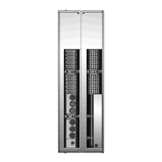
Quad edr receiver
Hide thumbs
Also See for Prisma II:
- Installation and operation manual (146 pages) ,
- Technical bulletin (18 pages) ,
- Installation manual (184 pages)
Table of Contents
Troubleshooting

Related Manuals for Cisco Prisma II


Summary of Contents for Cisco Prisma II
- Page 1 Cisco Prisma II Quad EDR Receiver Installation Guide...
-
Page 3: For Your Safety
For Your Safety Explanation of Warning and Caution Icons Avoid personal injury and product damage! Do not proceed beyond any symbol until you fully understand the indicated conditions. The following warning and caution icons alert you to important information about the safe operation of this product: You may find this symbol in the document that accompanies this product. - Page 4 Trademark Acknowledgments Cisco and the Cisco logo are trademarks or registered trademarks of Cisco and/or its affiliates in the U.S. and other countries. To view a list of Cisco trademarks, go to this URL: www.cisco.com/go/trademarks. Third party trademarks mentioned are the property of their respective owners.
-
Page 5: Table Of Contents
Contents Important Safety Instructions Safe Operation for Software Controlling Optical Transmission Equipment Warning Labels Module Introduction Receiver Description ......................25 Receiver Overview ....................25 Receiver Features ....................25 Receiver Operation ....................25 Receiver Operating Modes ..................29 Receiver Optical Input ................... 37 Laser Warning ...................... - Page 6 To Install the Receiver Modules in the Host Module ........56 To Install the Module in the Chassis ..............58 To Install the Module in a Prisma II XD Chassis ..........59 Cleaning Optical Connectors ..................... 61 Recommended Equipment ..................61 Tips for Optimal Fiber Optic Connector Performance ........
- Page 7 ICIM MAIN Menu ....................88 ICIM MAIN Menu Illustration ................89 Prisma II ICIM Menu ....................89 Prisma II MAIN Menu and ICIM Menu Structure ..........90 Receiver Software Menu Structure ............... 91 Checking the Operating Status using the ICIM ............... 94 To Check the Operating Status using ICIM ............
- Page 8 Contents Cable Requirements ....................109 Installing LCI ........................110 To Install the LCI Software .................. 110 Connecting Your Computer to the Chassis ..............114 To Connect a Computer to the Chassis .............. 114 Starting LCI Software ......................116 To Start LCI Software ................... 116 LCI Module Tree ........................
- Page 9 Contents Manufacturing Data Parameters ................ 150 Receiver Parameters for Compact Nodes ............... 151 Operating Status Parameters ................151 Control Parameters ....................154 Alarm Parameters ....................158 Manufacturing Data Parameters ................ 159 Receiver Parameters for GainMaker Nodes ..............160 Operating Status Parameters ................160 Control Parameters ....................
-
Page 11: Important Safety Instructions
Important Safety Instructions Important Safety Instructions Read and Retain Instructions Carefully read all safety and operating instructions before operating this equipment, and retain them for future reference. Follow Instructions and Heed Warnings Follow all operating and use instructions. Pay attention to all warnings and cautions in the operating instructions, as well as those that are affixed to this equipment. -
Page 12: Installation Requirements
Important Safety Instructions is essential to safe operation and must be verified before connecting the power supply. Know the following safety warnings and guidelines: Dangerous Voltages - Only qualified service personnel are allowed to perform equipment installation or replacement. - Only qualified service personnel are allowed to remove chassis covers and access any of the components inside the chassis. - Page 13 Important Safety Instructions Equipment Placement WARNING: Avoid personal injury and damage to this equipment. An unstable mounting surface may cause this equipment to fall. To protect against equipment damage or injury to personnel, comply with the following: Install this equipment in a restricted access location. ...
-
Page 14: Handling Precautions
Important Safety Instructions Rack Mounting Safety Precautions Mechanical Loading Make sure that the rack is placed on a stable surface. If the rack has stabilizing devices, install these stabilizing devices before mounting any equipment in the rack. WARNING: Avoid personal injury and damage to this equipment. Mounting this equipment in the rack should be such that a hazardous condition is not caused due to uneven mechanical loading. - Page 15 Important Safety Instructions tip-over. If the cart does not move easily, this condition may indicate obstructions or cables that may need to be disconnected before moving this equipment to another location. Avoid quick stops and starts when moving the cart. ...
- Page 16 Important Safety Instructions requires connection to a 3-terminal mains supply outlet via a 3-terminal power cord for proper connection to the protective ground. Note: The equipotential bonding terminal provided on some equipment is not designed to function as a protective ground connection. Class II Mains Powered Equipment –...
- Page 17 Important Safety Instructions Connection to -48 V DC/-60 V DC Power Sources If this equipment is DC-powered, refer to the specific installation instructions in this manual or in companion manuals in this series for information on connecting this equipment to nominal -48 V DC/-60 V DC power sources. Circuit Overload Know the effects of circuit overloading before connecting this equipment to the power supply.
-
Page 18: Fuse Replacement
Important Safety Instructions Labels - Do not remove any warning labels. Replace damaged or illegible warning labels with new ones. Covers - Do not open the cover of this equipment and attempt service unless instructed to do so in the instructions. Refer all servicing to qualified service personnel only. - Page 19 Important Safety Instructions Do not attempt to recharge ‘disposable’ or ‘non-reusable’ batteries. Please follow instructions provided for charging ‘rechargeable’ batteries. Replace batteries with the same or equivalent type recommended by manufacturer. Do not expose batteries to temperatures above 100° C (212° F). ...
-
Page 20: Emc Compliance Statements
Important Safety Instructions Electromagnetic Compatibility Regulatory Requirements This equipment meets applicable electromagnetic compatibility (EMC) regulatory requirements. Refer to this equipment's data sheet for details about regulatory compliance approvals. EMC performance is dependent upon the use of correctly shielded cables of good quality for all external connections, except the power source, when installing this equipment. - Page 21 Important Safety Instructions area is likely to cause harmful interference in which case users will be required to correct the interference at their own expense. Industry Canada - Industrie Canadiene Statement This apparatus complies with Canadian ICES-003. Cet appareil est confome à la norme NMB-003 du Canada. CENELEC/CISPR Statement with Respect to Class A Information Technology Equipment This is a Class A equipment.
-
Page 22: Safe Operation For Software Controlling Optical Transmission Equipment
Safe Operation for Software Controlling Optical Transmission Equipment Safe Operation for Software Controlling Optical Transmission Equipment If this manual discusses software, the software described is used to monitor and/or control ours and other vendors’ electrical and optical equipment designed to transmit video, voice, or data signals. -
Page 23: Warning Labels
Warning Labels Warning Labels The following labels are located on this product. Laser Warning Label * Product and Laser Information Label * Located on host module only (not applicable to receiver module). -
Page 24: Module Introduction
Chapter 1 Module Introduction xxii... - Page 25 Overview This chapter describes the Cisco Prisma II Quad Enhanced Digital ® ® Return (QEDR) Receiver Module. Note: This product uses the FreeRTOS real time operating system (v 8.2.1). The source code can be obtained from http://www.FreeRTOS.org. FreeRTOS is a free software; it can be redistributed and/or modified...
-
Page 26: In This Chapter
Module parameter descriptions Document Version This is the first release of this guide. Related Publication You may find the following publication useful as you implement the procedures in this document. Prisma II Software Upgrade Program (SOUP) Installation Guide... -
Page 27: Receiver Description
The receiver module installs into a Prisma II XD Chassis directly, or into a standard Prisma II Chassis by means of a host module that accepts up to two Prisma II High Density application modules. The receiver front panel contains two optical pluggable module (OPM) connectors that provides inputs for four separate optical receiver circuits. - Page 28 The receiver supports 2.5 GHz (1:1) and 5 GHz (2:1) configurations in an XD form factor for both Prisma II (using Host Module) and Prisma XD Chassis. The OPM optical input uses a dual LC/PC connector and supports all standard reverse bandwidths: 40, 42, 55, 65, and 85 MHz.
- Page 29 2:1 Input (5 GHz), Two RF Outputs, One OPM 2:1 Input (5 GHz), Two RF Output, Two OPMs The factory default operating mode is 2:1 Input, One RF Output, Two OPMs; other modes can be selected by the user. For additional details on these operating modes, see Receiver Operating Modes (on page 28).
-
Page 30: Receiver Block Diagram
Chapter 1 Module Introduction Receiver Block Diagram Referring to the block diagram above (or below). The top OPM accepts two optical inputs. The optical signals are converted to digital, unscrambled and converted back to RF by DACs 1 and 3. These are signals are then routed to the top RF output (A) through an RF switch network. -
Page 31: Receiver Operating Modes
individual 2.5 G streams within a 5G stream. These controls do not turn off the DACs. The RF Ports control controls whether just the top RF output port (A) is used or both RF output ports (A and B) are used. The switching options are discussed in the section below. - Page 32 Chapter 1 Module Introduction back to analog RF signals. The RF signals for transmitter #1 and transmitter #2 are combined and sent to the RF Out Port A on the back of the module.
- Page 33 Receiver Description 1:1 Input, One RF Output, Two OPMs Referring to the diagram below, each QEDR transmitter digitizes a single RF signal into a serial stream and transmits it over optical fiber to the receiver. At the receiver, the serial streams from four separate transmitters are deserialized and converted back to analog RF signals.
- Page 34 Chapter 1 Module Introduction back to analog RF signals. The RF signal for transmitter #1 is sent to the RF Out Port A, the RF signal for transmitter #2 is sent to the RF Out Port B.
- Page 35 Receiver Description 1:1 Input, Two RF Outputs, Two OPMs Referring to the diagram below, each QEDR transmitter digitizes a single RF signal into a serial stream and transmits it over optical fiber to the receiver. At the receiver, the serial streams from four separate transmitters are deserialized and converted back to analog RF signals.
- Page 36 Chapter 1 Module Introduction transmitter #2 are combined and sent to the RF Out Port A on the back of the module. Any of the four RF signals on RF Out Port A can be muted.
- Page 37 Receiver Description 2:1 Input, One RF Output, Two OPMs Referring to the diagram below, each QEDR transmitter digitizes two RF signals into a serial stream and transmits it over optical fiber to the receiver. At the receiver, the serial streams from four separate transmitters are deserialized and converted back to analog RF signals.
- Page 38 Chapter 1 Module Introduction analog RF signals. The RF signals for transmitter #1 are sent to the RF Out Port A, the RF signals for transmitter #2 are sent to the RF Out Port B. 2:1 Input, Two RF Output, Two OPMs Referring to the diagram below, each QEDR transmitter digitizes two RF signal into a serial stream and transmits it over optical fiber to the receiver.
-
Page 39: Receiver Optical Input
Receiver Description and sent to the RF Out Port A, the RF signals for transmitter #2 and transmitter #4 are combined and sent to the RF Out Port B. Receiver Optical Input The optical input is a dual LC/PC connector in an OPM. Laser Warning WARNING: Avoid damage to your eyes! Do not look into any optical connector while the... -
Page 40: Receiver Front And Back Panel
Chapter 1 Module Introduction Receiver Front and Back Panel Receiver Illustration (Front and Back) -
Page 41: Receiver Front Panel Features
Receiver Front and Back Panel Receiver Front Panel Features Part Function Alarm Indicator LED Illuminates or blinks when an alarm condition occurs. Power On Indicator LED Illuminates when power is supplied to the module. Glows steadily to indicate Master, Single, or Active Slave operation. -
Page 42: Back Panel Connectors
Chapter 1 Module Introduction Back Panel Connectors Blind-mate connectors make it easy to install this module. The push-on connector on the back of the module mates with the back plane bus connector inside the chassis. This 55-pin connector and the two RF connectors provide the following facilities. RF signal connections ... -
Page 43: Host Module
Host Module Host Module A host module is required to mount the application module in a standard Prisma II Chassis. The host module doubles the density of the Prisma II Chassis by providing two high density module slots for each current Prisma II slot. Its simple design allows for efficient routing of RF and electrical signal between the chassis back plane and each high density module. -
Page 44: Host Module Illustration
Chapter 1 Module Introduction Host Module Illustration Front View Back View... -
Page 45: Host Module Back Panel Connectors
Host Module Side View Host Module Back Panel Connectors Blind-mate connectors make it easy to install the host module. The push-on connector on the back of the module mates with the back plane bus connector inside the chassis. This 110-pin connector provides the following facilities: RF signal input connection ... -
Page 46: Module Configuration
If an ICIM2 or ICIM2-XD is installed, a command line interface (CLI) is available that can be used to configure and monitor all Prisma II modules in the ICIM domain. The CLI is available locally (RS-232) or remotely via Telnet. For details, see the configuration guide for your Prisma II system release. -
Page 47: Configuration Summary
Module Configuration Configuration Summary You can use any of the methods listed above to perform the following configuration tasks: Enable or disable each receiver channel Force Mute Force Alarm (to check redundant modules, only works when the receiver is in ... -
Page 49: Module Installation
Chapter 2 Module Installation Introduction This chapter contains instructions for installing the module and describes the site requirements, equipment, and tools needed for module installation. In This Chapter Preparing for Installation ..............48 Site Requirements ................. 49 Connecting the RF Cables to the Chassis .......... -
Page 50: Preparing For Installation
Unpacking and Inspecting the Module As you unpack the module, inspect it for shipping damage. If you find any damage, contact Cisco Services. Refer to Customer Information (on page 139) for contact information. Equipment and Tools Needed Before you begin, make sure that the module is in good condition. -
Page 51: Site Requirements
Site Requirements Site Requirements Before you begin, make certain that your installation site meets the requirements discussed in this section. Access Requirements WARNING: Use this product in locations that restrict access to all persons who are not authorized. Otherwise, personal injury or equipment damage may occur. Ensure that only authorized personnel have access to this equipment. -
Page 52: Power Requirements
Space Requirements This is a single-width, half-height module. Actual space requirements depend on whether the module is installed in a Prisma II standard or a Prisma II XD chassis. Prisma II Standard Chassis Installation When installed in a Prisma II standard chassis, the module is placed in a host module and then inserted into the chassis in slots 5 through 16. -
Page 53: Prisma Ii Standard Chassis Style
Site Requirements Prisma II Standard Chassis Style The Prisma II standard chassis may be configured as front-access or rear-access depending on the system you have purchased. Power, RF input or output, and other connectors may be located on either the front or rear of the chassis. Connections to the chassis serve the same function and are made in the same manner regardless of the location of the connectors or chassis configuration. - Page 54 Module Installation Front-Access Chassis - Front Panel Illustration The following illustration shows the front of the front-access Prisma II standard chassis with two power supplies, 10 full-height modules, and the ICIM installed. The power inlets, RF input/output, and RF ports are located on the recessed bottom...
-
Page 55: Prisma Ii Xd Chassis Style
Site Requirements Prisma II XD Chassis Style The Prisma II XD chassis back panel serves as both a connector panel and a receptacle for AC power supply modules and the ICIM2-XD, when installed. The RF connectors are arranged in pairs, and each pair is numbered to identify its corresponding module slot. -
Page 56: Connecting The Rf Cables To The Chassis
Complete the appropriate procedure below to connect RF cables for the module. Note: This procedure assumes that the chassis is mounted in a rack. Standard Prisma II Chassis Note: This procedure assumes a host module with receivers in both lower and upper half-slot positions. - Page 57 If F connectors are installed, use a 7/16-in. open-end wrench to secure all cables to the connectors at the chassis. Prisma II XD Chassis Attach a 75-ohm RF cable to the appropriate RF destination. Locate the RF ports at the back of the chassis. In this diagram, the RX1 and RX3 are routed to Port A, RX2 and RX4 are routed to Port B.
-
Page 58: Installing The Module In The Chassis
All Prisma II high-density application modules must be installed in a host module before they can be mounted in a standard Prisma II Chassis. Prisma II host modules prior to Rev C (date codes through A2006) do not support the Controller Area Network (CAN) bus. - Page 59 Installing the Module in the Chassis Complete the following steps to install the application modules in the host module. Align the ridges on the top and bottom of the module with the guide slots located on the host module and the chassis. Be careful to keep the module level as you slide it into the host to avoid bending the pins on the host back plane.
-
Page 60: To Install The Module In The Chassis
Chapter 2 Module Installation To Install the Module in the Chassis Note: This procedure assumes that the chassis is mounted in a rack. Locate the fiber guides at the bottom of the chassis and the module guide slots inside the chassis as shown in the following illustration. Align the ridges on the top and bottom of the host module with the guide slots on the chassis. -
Page 61: To Install The Module In A Prisma Ii Xd Chassis
Fill any unused chassis slots with module blanks to help ensure proper cooling air flow. Blanks for high density modules are available to fill unused host module slots. To Install the Module in a Prisma II XD Chassis Note: This procedure assumes that the chassis is installed in a rack. WARNING: Avoid damage to your eyes! Do not look into any optical connector while the system is active. - Page 62 Chapter 2 Module Installation Locate the fiber guides at the bottom of the chassis and the module guide slots inside the chassis as shown in the following illustration. Align the ridges on the top and bottom of the module with the module guide slots located on the chassis.
-
Page 63: Cleaning Optical Connectors
Cleaning Optical Connectors Cleaning Optical Connectors CAUTION: Proper operation of this equipment requires clean optical fibers. Dirty fibers will adversely affect performance. Proper cleaning is imperative. The proper procedure for cleaning optical connectors depends on the connector type. The following describes general instructions for fiber optic cleaning. Use your company's established procedures, if any, but also consider the following. -
Page 64: To Clean Optical Connectors
Chapter 2 Module Installation To Clean Optical Connectors Warning: Avoid personal injury! Use of controls, adjustments, or procedures other than those specified herein may result in hazardous radiation exposure. Avoid personal injury! The laser light source on this equipment (if a transmitter) or the fiber cables connected to this equipment emit invisible laser radiation. -
Page 65: Connecting Optical Cables
Avoid direct exposure to the laser light source. Ensure that the fiber cable is terminated before "fishing." The Fiber Fish tool that was shipped with the Prisma II Chassis is used to pull an optical cable from the rear of the chassis to the front of the chassis so the optical cables can be connected to optical connectors on the front panel of the modules. -
Page 66: Cable Routing - Prisma Xd Chassis
Chapter 2 Module Installation To Pull the Optical Cable to the Module Insert the Fiber Fish tool through the slot located just above the bottom of the chassis. At the rear of the chassis, locate the appropriate optical cable. Insert the optical cable into the notched area of the Fiber Fish tool as shown below. -
Page 67: To Connect Optical Cables To Module
Connecting Optical Cables To Connect Optical Cables to Module Important: Observe laser safety precautions. Refer to Laser Safety information earlier in this guide. Note: This procedure assumes that the chassis is mounted in a rack and that the optical cable has been installed at the node. CAUTION: The OPM is sensitive to electrostatic discharge. - Page 68 Chapter 2 Module Installation Route the other end of the optical cable to the appropriate destination.
-
Page 69: Connecting The Icim To Additional Chassis
ICIM IN and ICIM OUT Connectors Every Prisma II standard and Prisma II XD chassis has a DB9 ICIM IN and a DB9 ICIM OUT connector for the purpose of chassis-to-chassis ICIM connections. ICIM IN is a female connector and ICIM OUT is a male connector. -
Page 70: To Connect Chassis-To-Chassis Icim In And Icim Out Ports
Chapter 2 Module Installation locally or from the factory. The chassis data sheet lists the part number for a 6-foot DB9 Female to DB9 Male serial extension cable. The connectors are a serial 9-pin D- shell (EIA 574/232). To Connect Chassis-to-Chassis ICIM IN and ICIM OUT Ports Connect the serial extension cable from the ICIM OUT of the chassis containing the ICIM to the ICIM IN connector of the second chassis. -
Page 71: Configuring Redundancy
107). External Alarm Connections The Prisma II Standard and XD Chassis can be configured for local hard-wired redundancy using the ALARM IN and ALARM OUT connectors located on the connector interface panel. A pair of application modules can be configured in a Master-Slave relationship so that, if the Master fails, the Slave takes over in response to ALARM IN and ALARM OUT signaling. -
Page 72: Alarms In And Alarms Out Connectors
Module Installation ALARMS IN and ALARMS OUT Connectors Every Prisma II standard and Prisma II XD chassis provides connectors for external alarms to and from each module slot. These alarm connectors are located on the chassis connector panel and are labeled ALARMS IN and ALARMS OUT. -
Page 73: Alarms In And Alarms Out Connector Illustration
Configuring Redundancy ALARMS IN and ALARMS OUT Connector Illustration Prisma II Standard Chassis Prisma II XD Chassis... -
Page 74: Master/Slave Illustration
Master/Slave Illustration Redundancy Interface Panel The Prisma II Redundancy Interface Panel is an accessory to the Prisma II platform. It is intended to be used with the master/slave feature and the contact closure alarm feature of the Prisma II platform. -
Page 75: Prisma Ii Redundancy Interface Panel Illustrations
Configuring Redundancy Prisma II Redundancy Interface Panel Illustrations Front Panel Back Panel Close-up of Front Panel Terminal Strips... -
Page 77: Operation Using Icim
Chapter 3 Operation using ICIM Introduction The procedures in this chapter apply if you are using the Prisma II ICIM2 front-panel interface to configure and operate the module. For information on using CLI commands or the ICIM Web Interface to configure and operate the module, see the Configuration Guide for your system release. - Page 78 Chapter 3 Operation using ICIM In This Chapter ICIM Introduction ................. 77 ICIM2 Front Panel ................79 ICIM Password ..................82 Operating the ICIM ................88 Checking the Operating Status using the ICIM........ 94 Configuring the Module using the ICIM ..........
-
Page 79: Icim Introduction
The ICIM can also be navigated remotely using CLI commands or the ICIM Web Interface. For additional information, see the configuration guide for your Prisma II system release. Important: Do not operate any Prisma II Chassis without a fan tray installed properly. If a ... -
Page 80: Icim Block Diagram
Chapter 3 Operation using ICIM fan tray is not installed in the Prisma II Chassis, the ICIM will not communicate with any of the modules in that chassis. All chassis connected in a daisy-chain must be powered and have a fan tray ... -
Page 81: Icim2 Front Panel
ICIM2 Front Panel ICIM2 Front Panel ICIM2 Illustration (Front Panel) -
Page 82: Icim2 Front Panel Features
Glows when a link is established on the Ethernet port. Ethernet connector RS232 connector Used to connect a PC to the Prisma II system for CLI communication and setup. ICIM LCD The ICIM LCD is the operator’s visual link to the ICIM software. When the ICIM is installed and powered up, the MAIN menu is displayed on the LCD. -
Page 83: Icim Keypad
ICIM2 Front Panel ICIM Keypad The ICIM keypad has 12 keys that allow you to input and monitor operational parameters. Each key and a brief description of its function are shown here. Button Function Displays status information for the selected module. Displays configuration information for the selected module. -
Page 84: Icim Password
ICIM Password The ICIM allows you to send configuration commands, change alarm thresholds, and restore factory default settings in Prisma II modules. To prevent unauthorized changes to these parameters, you have the option of using a password protection system. Password authorization only applies to configurable parameters. Status and alarm information is always available on the ICIM, regardless of password implementation. -
Page 85: To Access The Password Menu
ICIM Password To Access the Password Menu The Password menu allows you to create, enter, change, or disable the user password. It also allows service personnel to use the factory default password. Press the key. Use the key to scroll down until Password is highlighted. Press the key. -
Page 86: To Enter The User Password
Chapter 3 Operation using ICIM To Enter the User Password To use the user password feature, you must create and enter a password of exactly eight digits using only the 0-9 number keys. The password remains active for 10 minutes after your last keystroke. To change configuration parameters after 10 minutes, you must re-enter your password. -
Page 87: To Change The User Password
ICIM Password I C I M I C I M I C I M I C I M S h e l f S h e l f S h e l f S h e l f S l o t S l o t S l o t S l o t... -
Page 88: To Disable The User Password Using Icim
Chapter 3 Operation using ICIM enter an 8-digit password using only the 0-9 number keys. Press the to input the password. I C I M I C I M I C I M I C I M S h e l f S h e l f S h e l f S h e l f... - Page 89 ICIM Password expired (more than 10 minutes have passed since your last keystroke), you must re- enter the current password before disabling it. Press the key. Use the key to scroll down until Password is highlighted. Press the key. Use the key to scroll down until Disable Psw is highlighted.
-
Page 90: Operating The Icim
Chapter 3 Operation using ICIM Operating the ICIM Using the ICIM Once the module is installed, it runs without the aid of an operator. Unless alarms are generated or your system configuration changes, you should not need to make any adjustments to the module beyond the initial setup. To Access the ICIM LCD Contrast To access the ICIM LCD contrast control from the MAIN menu, press the key. -
Page 91: Icim Main Menu Illustration
Operating the ICIM ICIM MAIN Menu Illustration The ICIM MAIN menu is shown below. Prisma II ICIM Menu To display the ICIM menu, press the key. The ICIM menu appears. Press the key to select the specific option. Display Description Shelf Displays the location of the ICIM2 or ICIM2-XD. -
Page 92: Prisma Ii Main Menu And Icim Menu Structure
U p d a t e A d r U p d a t e A d r TP016 Prisma II MAIN Menu and ICIM Menu Structure Pressing the key initiates the MAIN software menu. Pressing the initiates the ICIM2 or ICIM2-XD software menu. The MAIN and ICIM software structures are shown below. -
Page 93: Receiver Software Menu Structure
Operating the ICIM Receiver Software Menu Structure From the MAIN or SCROLL menus, you can navigate to the MODULE menu. From the MODULE menu, press the , or key to display the desired parameter menu. - Page 94 Chapter 3 Operation using ICIM MAIN or Mfg. Data MAIN or MAIN or SCROLL Module Type SCROLL SCROLL Serial # Menu Menu Menu Date Code Sw Ver Script Ver MODULE MODULE MODULE In Service Hrs Menu Menu Menu Spec Data Restore STAT ALARMS...
- Page 95 Operating the ICIM As shown above, additional parameters appear in these menus depending on the type of node connected and node configuration. Due to space limitations, the CONFIG menus may display status indicators as well as configurable parameters. For details on all node parameters, see Module Parameter Descriptions (on page ...
-
Page 96: Checking The Operating Status Using The Icim
Chapter 3 Operation using ICIM Checking the Operating Status using the ICIM To Check the Operating Status using ICIM You can use the ICIM to check the status of all operating parameters of this module. All status information is displayed on the ICIM LCD. At the MAIN menu, press the key to highlight the Shelf and Slot fields. -
Page 97: Status Menus
Checking the Operating Status using the ICIM STATUS Menus Press the key to select the STATUS menu. Typical STATUS menus are shown below. S T A T U S S T A T U S S T A T U S S h e l f S h e l f S h e l f... -
Page 98: Configuring The Module Using The Icim
Chapter 3 Operation using ICIM Configuring the Module using the ICIM To Configure Parameters using the ICIM You can use the ICIM to configure the parameters of this module. From the MAIN menu, press the key to highlight the Shelf and Slot fields. -
Page 99: Alarm Threshold Menus
Configuring the Module using the ICIM Alarm Threshold Menus Some typical alarm threshold menus are shown below. S T A T U S S T A T U S S h e l f S h e l f S l o t S l o t P 2 - H D - Q E D R P 2 - H D - Q E D R... - Page 100 Chapter 3 Operation using ICIM field, the Up and Down arrows will scroll through the parameters that are specific to this module. Sample CONFIG menus are shown below. C O N F I G C O N F I G C O N F I G S h e l f S h e l f...
-
Page 101: Checking Alarms Using The Icim
Checking Alarms using the ICIM Checking Alarms using the ICIM To Check Alarms using ICIM Alarms fall into one of the following categories. Major low Minor low Minor high Major high Boolean ... - Page 102 Chapter 3 Operation using ICIM If the red ALARM LED on the front panel is blinking, a minor alarm condition is indicated. If the ALARM LED on the front panel is illuminated, a major alarm conditions is indicated. From the MAIN menu, press the key to highlight the Shelf and Slot fields.
-
Page 103: Alarms Menus
Checking Alarms using the ICIM ALARMS Menus When a module ALARMS menu is selected, press the key or the to scroll through alarms. Some typical ALARMS menus are shown below. A L A R M S A L A R M S A L A R M S A L A R M S S h e l f... -
Page 104: To Set Adjustable Alarm Thresholds Using The Icim
Chapter 3 Operation using ICIM To Set Adjustable Alarm Thresholds using the ICIM You can use the ICIM to change the adjustable alarm thresholds of this module from their factory default values. At the MODULE menu, press the key. The STATUS menu appears on the ICIM LCD. -
Page 105: Checking Manufacturing Data Using The Icim
Checking Manufacturing Data using the ICIM Checking Manufacturing Data using the ICIM To Check Manufacturing Data You can display the manufacturing data for this module on the ICIM LCD. Complete the following steps to access the manufacturing data. From the MAIN menu, press the key to highlight the Shelf and Slot fields. -
Page 106: Mfg. Data Menus
Chapter 3 Operation using ICIM MFG. DATA Menus When the MFG. DATA menu is selected, the key or the key allows you to scroll through the manufacturing parameters specific to this module. Sample MFG. DATA menus are shown below. M F G . D A T A M F G . -
Page 107: Saving The Configuration Using The Icim
Saving the Configuration using the ICIM Saving the Configuration using the ICIM To Save the Current Configuration After you have changed a parameter or entered data, press the key to save the changes and return to the MAIN menu. The ICIM will report "SUCCESS" if the changes were accepted. -
Page 108: Adjusting Alarm Thresholds
Chapter 3 Operation using ICIM Adjusting Alarm Thresholds To Adjust Alarm Thresholds Relative alarm thresholds are both displayed and stored as relative values. This method for adjusting alarm thresholds lets you choose any valid increment size and adjust the alarm threshold to any valid value. You can use the ICIM to change the adjustable alarm thresholds of this module from their factory default values. -
Page 109: Operation Using Lci
Chapter 4 Operation using LCI Introduction This chapter provides instructions for installing and using the LCI. This chapter applies if you are using the LCI to operate a module. In This Chapter LCI Introduction ................. 108 System Requirements ................. 109 ... -
Page 110: Lci Introduction
LCI Introduction LCI Function LCI is software that functions as a user interface for the Prisma II platform. LCI is installed on a computer, which is then connected to a Prisma II Chassis. Using LCI, you can configure and monitor the modules in the chassis to which the computer is connected. -
Page 111: System Requirements
System Requirements System Requirements You will need the following computer software and hardware to run LCI. Computer Requirements Pentium II 300 MHz processor or equivalent 128 MB RAM 10 MB available hard drive space CD-ROM Drive Windows 95 or later operating system software ... -
Page 112: Installing Lci
Obtain the LCI installation program from www.cisco.com/support and copy the program file to your Windows desktop. Note: If you need help locating the LCI installation program, contact Cisco Services at 1-800-283-2636 for assistance. Launch the LCI installation program. The Welcome screen appears as shown in the following illustration. - Page 113 Installing LCI Click Install to begin installation. After a moment, the Setup Status screen appears, displaying a progress indicator as shown in the following illustration.
- Page 114 Chapter 4 Operation using LCI When finished, the "wizard" asks if you want to install the Silicon Labs driver, which is required when using LCI with a node product. If you are using LCI with a node product, choose the Launch option, click Next, and follow steps of the wizard to install the driver.
- Page 115 Installing LCI Click Finish to exit the Install wizard. An LCI shortcut is placed on your Windows desktop as shown in the following illustration. The LCI software is now ready to use.
-
Page 116: Connecting Your Computer To The Chassis
Complete the following steps to connect your computer to the chassis. Plug one end of a 9-pin RS-232 serial extension cable into your computer. Plug the other end of the cable into the LCI port, labeled Local Craft Interface. Standard Prisma II Chassis... - Page 117 Connecting Your Computer to the Chassis Prisma II XD Chassis (Top Right Corner Detail)
-
Page 118: Starting Lci Software
Chapter 4 Operation using LCI Starting LCI Software When you start LCI, it polls the module(s) located in the chassis to which your computer is attached. For each module it finds, LCI does the following: Represents the module in the module tree of the main LCI window ... - Page 119 Starting LCI Software In the LCI Detect Configuration window, select the appropriate COM port, chassis ID, and chassis type, and then click Start. Result: LCI polls the modules in the chassis, and when finished, displays a Refresh Complete message. Click OK to continue with LCI startup. Result: The main LCI window appears as shown in the example below.
-
Page 120: Lci Module Tree
Chapter 4 Operation using LCI LCI Module Tree The LCI main window contains a tree that represents your system in a hierarchical manner. Note: You may need to refresh the module tree once the node is unplugged from your system due to the loss of connection. Module Tree The module tree represents a computer connected to a chassis that contains five modules. -
Page 121: Accessing The Module Detail Information
Accessing the Module Detail Information Accessing the Module Detail Information The Module Details window displays information about module parameters, alarms, and status. You can access this window from the module tree using any of these methods: Double-click the chassis and select the module in the graphic that appears. ... - Page 122 Chapter 4 Operation using LCI following example. If the module is changed to Master mode, an additional Manual Alarm control appears at the bottom of the Controls table, as shown in the following example:...
-
Page 123: To Access The Module Details, Right-Click The Module
Accessing the Module Detail Information To Access the Module Details, Right-Click the Module Right-click the module, and then click Details. Result: The Module Details window appears. Proceed with viewing or configuring information. -
Page 124: Checking The Operating Status
Chapter 4 Operation using LCI Checking the Operating Status To Check Operating Status using LCI Using the LCI, you can check the status of all module operating parameters. In the module tree, right-click the module, and then click Details. The Module Details window appears as shown in the following example. The monitored parameters are displayed under Parameters and Status. - Page 125 Checking the Operating Status...
-
Page 126: Configuring The Module Using Lci
Chapter 4 Operation using LCI Configuring the Module using LCI To Configure Parameters using LCI Using LCI, you can configure any module parameters that allow for such changes. In the module tree, right-click the module, and then click Details. The Module Details window appears as shown in the following example. Under Controls, double-click the parameter you want to configure. - Page 127 Configuring the Module using LCI Depending on the parameter you chose, select or type a new value. Click Execute. The new value appears next to the parameter. Note: For details on all configurable parameters, see Module Parameter Descriptions (on page 141).
-
Page 128: Checking The Module Alarms Using Lci
Chapter 4 Operation using LCI Checking the Module Alarms using LCI Using LCI, you can check the alarm status of various parameters. Alarms limits fall into one of the following categories. Major low Minor low Minor high Major high ... -
Page 129: To Check Alarms Using Lci
Checking the Module Alarms using LCI To Check Alarms using LCI Right-click the module, and then click Details. The Module Details window appears as shown in the following example. The alarms are shown under Parameters and Alarms. Note: For details on all alarm parameters, see Module Parameter Descriptions (on page 141). -
Page 130: Modifying Module Alarm Limits Using Lci
Chapter 4 Operation using LCI Modifying Module Alarm Limits using LCI To Modify Alarm Limits using LCI Using LCI, you can modify alarm limits for parameters that allow for such changes. In the module tree, right-click the module, and then click Details. The Module Details window appears as shown in the following example. - Page 131 Modifying Module Alarm Limits using LCI To change the limit value, type the desired value in the Command to box. Click Execute. The new value appears in the alarm limit column. Note: For details on all alarm limits, see Module Parameter Descriptions (on page 141).
-
Page 132: Checking Manufacturing Data Using Lci
Chapter 4 Operation using LCI Checking Manufacturing Data using LCI To Check Manufacturing Data using LCI Using LCI, you can check the manufacturing data for a selected module. In the module tree, right-click the module, and then click Details. The Module Details window appears as shown in the following example. The manufacturing data is displayed under Properties. -
Page 133: Maintenance And Troubleshooting
Chapter 5 Maintenance and Troubleshooting Introduction This chapter describes the maintenance guidelines and troubleshooting procedures for this Prisma II module. Qualified Personnel Only appropriately qualified and skilled personnel should attempt to install, operate, maintain, and service this product. WARNING: Allow only qualified and skilled personnel to install, operate, maintain, and service this product. -
Page 134: Maintenance
Chapter 5 Maintenance and Troubleshooting Maintenance The following maintenance is recommended to ensure optimal performance. Frequency Maintenance Required Check all parameters and test points. Yearly Record data. Make adjustments as needed. Make sure all cables are mated properly. ... -
Page 135: General Troubleshooting Information
General Troubleshooting Information General Troubleshooting Information This troubleshooting information describes the most common alarms and gives typical symptoms, causes, and items to check before contacting Customer Service. Equipment Needed You may need the following equipment to troubleshoot these modules. Digital voltmeter ... -
Page 136: Troubleshooting Alarm Conditions
Chapter 5 Maintenance and Troubleshooting Troubleshooting Alarm Conditions Module Alarm Conditions If the red ALARM indicator is illuminated, check the display on the front panel to determine the cause of the alarm. The following tables list possible alarm conditions, causes, and solutions. Note: Tx1Pwr - Tx4Pwr and Rx1Pwr - Rx4Pwr alarms are not applicable to GainMaker Node transmitters. - Page 137 Troubleshooting Alarm Conditions Alarm Function Possible Causes Possible Solutions Power supply failure Check power supply PsOk Bus voltage status LCI cable Check LCI cable Communication Status of LCI disconnected Status communication Replace receiver with module ...
- Page 138 Chapter 5 Maintenance and Troubleshooting Alarm Function Possible Causes Possible Solutions Degraded signal Check, clean fiber Rx1_Data Loss of data for Low input power Check transmitter output power Degraded transmitter Wrong mode selected ...
- Page 139 Troubleshooting Alarm Conditions Alarms Specific to Compact Nodes Alarm Function Possible Causes Possible Solutions Low or no input Replace module NdRx1LOS Loss of input power at node receiver signal on Node Check for other input Rx 1 alarms indicating ...
-
Page 141: Customer Information
Chapter 6 Customer Information If You Have Questions If you have technical questions, call Cisco Services for assistance. Follow the menu options to speak with a service engineer. Access your company's extranet site to view or order additional technical publications. For accessing instructions, contact the representative who handles your account. -
Page 143: Appendix A Module Parameter Descriptions
Module Parameter Descriptions Introduction This appendix provides manufacturing data, monitored parameters, configurable parameters, and alarms for the Prisma II Quad EDR Receiver module and its associated node. The examples shown in the tables are for guidance only. CAUTION: The warranty may be voided and the equipment damaged if you operate the equipment above the specified temperature limits (131°... -
Page 144: Receiver Parameters For Gs7000 Nodes
Appendix A Module Parameter Descriptions Receiver Parameters for GS7000 Nodes Operating Status Parameters Parameter ICIM Function Operating Name (LCI) Abbreviation Range Module ModTemp Displays module temperature -40 º C to Temperature 100 º C Receiver 1 Type RcvType1 Displays the receiver type, Standard Std or Ext (Std) or Extended Range (Ext), as Receiver 2 Type... - Page 145 Receiver Parameters for GS7000 Nodes Note: All parameters below this point in the table relate to the attached node and are monitor-only. Tx Type TxType Indicates the type of transmitter 2:1 or 1:1 connected to the receiver Tx OPM Type Tx_OPM Indicates whether the OPM installed Compliant or...
-
Page 146: Control Parameters
Appendix A Module Parameter Descriptions Control Parameters... - Page 147 Receiver Parameters for GS7000 Nodes Parameter ICIM Description Values Default Name (LCI) Abbreviation Mode Select Mode Module redundancy control. If set 0: Slave Single to Master, the unit is only 1: Single controlled by the Enable control. 2: Master If set to Slave, the unit is controlled by the Enable control and the external input CNT_IN.
- Page 148 Appendix A Module Parameter Descriptions Parameter ICIM Description Values Default Name (LCI) Abbreviation Rx Mode RxMode Sets the receiver operating mode 0: 5GHz 5GHz 2.5GHz or 5GHz. 1: 2.5GHz Note: Changing the Rx Mode forces the FPGA to be reprogrammed. This takes about 10 seconds, so user may notice a delay before the change takes effect.
- Page 149 Receiver Parameters for GS7000 Nodes Parameter ICIM Description Values Default Name (LCI) Abbreviation Rx 1 Power Level NdRx1Pwr Indicates the output power of Rx1, Rx2, Rx3, or Rx4. Rx 2 Power Level NdRx2Pwr Rx 3 Power Level NdRx3Pwr Rx 4 Power Level NdRx4Pwr Parameter value can be modified by the user using the ICIM2 or ICIM2-XD, LCI software, ROSA software, CLI commands, or the ICIM Web Interface.
-
Page 150: Alarm Parameters
Appendix A Module Parameter Descriptions Alarm Parameters Parameter ICIM Description Major Minor Minor Major Operating Name (LCI) Abbreviation High High Range Power PsOk Alarm if +24 or -5V fails OK or Supply Alarm Status Rx1_LOS Loss of Node optical signal -18.0 -15.0 -10.0... -
Page 151
Receiver Parameters for GS7000 Nodes Alarm threshold values can be modified by the user using the ICIM2 or ICIM2-XD, LCI software, ROSA software, CLI commands, or the ICIM Web Interface. Note the logical sequence of the alarm parameters. Major Low
Page 152: Manufacturing Data Parameters
Appendix A Module Parameter Descriptions Manufacturing Data Parameters Parameter ICIM Typical Values Name (LCI) Abbreviation Name Module name P2-HD-QEDR-RX Module Type Type number 2040 (GS7000 PNP) 2041 (Compact PNP) 2042 (GainMaker) Description Quad EDR Receiver Software Revision 1.00.46 Script Version Serial Number mfg serial # string ^ABCDEFG...Page 153: Receiver Parameters For Compact Nodes
Receiver Parameters for Compact Nodes Receiver Parameters for Compact Nodes Operating Status Parameters...- Page 154 Appendix A Module Parameter Descriptions Parameter ICIM Function Operating Name (LCI) Abbreviation Range Module ModTemp Displays module temperature -40 º C to Temperature 100 º C Receiver 1 Type RcvType1 Displays the receiver type, Standard Std or Ext (Std) or Extended Range (Ext), as Receiver 2 Type RcvType2 determined by type of OPM installed...
- Page 155 Receiver Parameters for Compact Nodes Parameter ICIM Function Operating Name (LCI) Abbreviation Range Tx Firmware TxFwVer Displays the EDR transmitter Node Version firmware version Dependent Tx OPM TOS OPM_TOS OPM laser on time in hours Node dependent Tx OPM Type OPM_Type Displays the modulation type for the DWDM or...
Page 156: Control Parameters
Appendix A Module Parameter Descriptions Control Parameters...- Page 157 Receiver Parameters for Compact Nodes Parameter ICIM Description Values Default Name (LCI) Abbreviation Mode Select Mode Module redundancy control. If set 0: Slave Single to Master, the unit is only 1: Single controlled by the Enable control. 2: Master If set to Slave, the unit is controlled by the Enable control and the external input CNT_IN.
- Page 158 Appendix A Module Parameter Descriptions Parameter ICIM Description Values Default Name (LCI) Abbreviation Rx Mode RxMode Sets the receiver operating mode 0: 5GHz 5GHz 2.5GHz or 5GHz. 1: 2.5GHz Note: Changing the Rx Mode forces the FPGA to be reprogrammed. This takes about 10 seconds, so user may notice a delay before the change takes effect.
- Page 159 Receiver Parameters for Compact Nodes Parameter ICIM Description Values Default Name (LCI) Abbreviation Forward Receiver NdFwdRx Displays the currently active 0: PreferRx1 forward receiver, FRx1, FRx2, or 1: PreferRx2 None. 2: ForceRx1 3: ForceRx2 Return Path NdRP1Att Return path 1 or 2 attenuation 0: 0 dB (min atten) Attenuation 1 setting...
Page 160: Alarm Parameters
Appendix A Module Parameter Descriptions Alarm Parameters Parameter ICIM Description Major Minor Minor Major Operating Name (LCI) Abbreviation High High Range Power PsOk Alarm if +24 or -5V fails OK or Supply Alarm Status Rx1_LOS Loss of Node optical signal -18.0 -15.0 -10.0...Page 161: Manufacturing Data Parameters
Receiver Parameters for Compact Nodes Manufacturing Data Parameters Parameter ICIM Typical Values Name (LCI) Abbreviation Name Module name P2-HD-QEDR-RX Module Type Type number 2040 (GS7000 PNP) 2041 (Compact PNP) 2042 (GainMaker) Description Quad EDR Receiver Software Revision 1.00.46 Script Version Serial Number mfg serial # string ^ABCDEFG...Page 162: Receiver Parameters For Gainmaker Nodes
Appendix A Module Parameter Descriptions Receiver Parameters for GainMaker Nodes Operating Status Parameters Parameter ICIM Function Operating Name (LCI) Abbreviation Range Module ModTemp Displays module temperature -40 º C to Temperature 100 º C Receiver 1 Type RcvType1 Displays the receiver type, Standard Std or Ext (Std) or Extended Range (Ext), as Receiver 2 Type...- Page 163 Receiver Parameters for GainMaker Nodes Note: All parameters below this point in the table relate to the attached node and are monitor-only. Tx Type TxType Indicates the type of transmitter 2:1 or 1:1 connected to the receiver Tx OPM Type Tx_OPM Indicates whether the OPM installed Compliant or...
Page 164: Control Parameters
Appendix A Module Parameter Descriptions Control Parameters...- Page 165 Receiver Parameters for GainMaker Nodes Parameter ICIM Description Values Default Name (LCI) Abbreviation Mode Select Mode Module redundancy control. If set 0: Slave Single to Master, the unit is only 1: Single controlled by the Enable control. 2: Master If set to Slave, the unit is controlled by the Enable control and the external input CNT_IN.
- Page 166 Appendix A Module Parameter Descriptions Parameter ICIM Description Values Default Name (LCI) Abbreviation Rx Mode RxMode Sets the receiver operating mode 0: 5GHz 5GHz 2.5GHz or 5GHz. 1: 2.5GHz Note: Changing the Rx Mode forces the FPGA to be reprogrammed. This takes about 10 seconds, so user may notice a delay before the change takes effect.
Page 167: Alarm Parameters
Receiver Parameters for GainMaker Nodes Alarm Parameters Parameter ICIM Description Major Minor Minor Major Operating Name (LCI) Abbreviation High High Range Power PsOk Alarm if +24 or -5V fails OK or Supply Alarm Status Rx1_LOS Loss of Node optical signal -18.0 -15.0 -10.0...Page 168: Manufacturing Data Parameters
Appendix A Module Parameter Descriptions Manufacturing Data Parameters Parameter ICIM Typical Values Name (LCI) Abbreviation Name Module name P2-HD-QEDR-RX Module Type Type number 2040 (GS7000 PNP) 2041 (Compact PNP) 2042 (GainMaker) Description Quad EDR Receiver Software Revision 1.00.46 Script Version Serial Number mfg serial # string ^ABCDEFG...Page 169: Glossary
Glossary ac, AC alternating current. An electric current that reverses its direction at regularly recurring intervals. automatic gain control. A process or means by which gain is automatically adjusted in a specified manner as a function of input level or other specified parameters. baseband digital reverse.- Page 170 Glossary DOCSIS Data Over Cable service Interface Specification. dual reverse receiver. EDFA erbium doped fiber amplifier. Optical fibers doped with the rare earth element, erbium, which can amplify light in the 1550 nm region when pumped by an external light source. enhanced digital return.
- Page 171 Glossary ICIM intelligent communications interface module. Internet protocol. A standard that was originally developed by the United States Department of Defense to support the internetworking of dissimilar computers across a network. IP is perhaps the most important of the protocols on which the Internet is based. It is the standard that describes software that keeps track of the internetwork addresses for different nodes, routes, and outgoing/incoming messages on a network.
- Page 172 Glossary optical modulation index, expressed in decimal or percentage notation. optical pluggable module. phase lock loop. An electronic servo system controlling an oscillator to maintain a constant phase angle relative to a reference signal. quadrature amplitude modulation. An amplitude and phase modulation technique for representing digital information and transmitting that data with minimal bandwidth.
- Page 173 Glossary status monitoring and control. The process by which the operation, configuration, and performance of individual elements in a network or system are monitored and controlled from a central location. SNMP simple network management protocol. A protocol that governs network management and the monitoring of network devices and their functions.
Page 175: Index
Connecting the ICIM to Additional Chassis • 61 Cable Requirements • 107 Connecting the RF Cables to the Chassis • 49 Cable Routing - Prisma II Chassis • 57 Connecting Your Computer to the Chassis • 112, Cable Routing - Prisma XD Chassis • 58 CAN •...- Page 176 Index Customer Information • 44, 96, 129, 135 HD • 156 dc, DC • 155 Host Module • 38 Default Community Strings • 100 Host Module Back Panel Connectors • 39 DFB laser • 155 Host Module Features • 38 DRR •...
- Page 177 MFG. DATA Menus • 94 Prisma II ICIM Menu • 82 MIB • 157 Modifying Module Alarm Limits using LCI • Prisma II MAIN Menu and ICIM Menu Structure • 83 Module Alarm Conditions • 130 Prisma II Redundancy Interface Panel Illustrations •...
- Page 178 Index Receiver Features • 24 STATUS Menus • 87 Receiver Front Panel Features • 36 System Requirements • 107 Receiver Illustration (Front and Back) • 36 Table of Inserted Modules • 102 Receiver Operating Modes • 26 Table of Removed Modules • 102 Receiver Operation •...
- Page 179 To Disable the User Password using ICIM • 79 To Enter the User Password • 76, 77 To Install the LCI Software • 108 To Install the Module in a Prisma II XD Chassis • 53 To Install the Module in the Chassis • 52 To Install the Receiver Modules in the Host Module •...
- Page 180 Fax: 408 527-0883 This document includes various trademarks of Cisco Systems, Inc. Please see the Notices section of this document for a list of Cisco Systems, Inc., trademarks used in this document. Product and service availability are subject to change without notice.