Lenovo ThinkSmart Hub 500 User Manual And Hardware Maintenance Manual
Skype room systems
Hide thumbs
Also See for ThinkSmart Hub 500:
- Deployment manual (21 pages) ,
- Safety, warranty, and setup manual (8 pages) ,
- Deployment manual (10 pages)
Table of Contents
Table of Contents

Related Manuals for Lenovo ThinkSmart Hub 500


Summary of Contents for Lenovo ThinkSmart Hub 500
- Page 1 Hub 500 User Guide and Hardware Maintenance Manual Machine Types: 10V5 and 10V6...
- Page 2 Important Product Information Guide and Appendix A “Notices” on page 59. First Edition (February 2018) © Copyright Lenovo 2018. LIMITED AND RESTRICTED RIGHTS NOTICE: If data or software is delivered pursuant to a General Services Administration “GSA” contract, use, reproduction, or disclosure is subject to restrictions set forth in Contract No. GS-...
-
Page 3: Table Of Contents
Removing the system cover ..Appendix B. Trademarks ..61 Replacing the video capture card ..© Copyright Lenovo 2018... - Page 4 Hub 500 User Guide and Hardware Maintenance Manual...
-
Page 5: Chapter 1. Overview
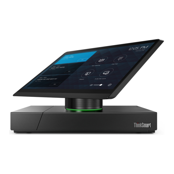
CAUTION: Move the meeting console by holding the base instead of the hinge or the LCD panel. Figure 1. Moving the meeting console Figure 2. Front view Internal microphones (2) Motion sensor System-status indicator (LED ring) © Copyright Lenovo 2018... - Page 6 Internal microphone Used to amplify your voice in a meeting without using an external microphone. Motion sensor When the meeting console is on, the motion sensor can detect whether you are in front of the screen. When you exit a meeting and move away from the meeting console, the screen will dim after several minutes (determined by your settings).
-
Page 7: Right-Side And Left-Side View
Right-side and left-side view Note: Your meeting console model might look slightly different from the illustration. Figure 3. Right-side and left-side view Power indicator Power button Internal speakers (2) Security-lock slot Power adapter connector HDMI out connectors (2) USB 3.1 Gen 1 connectors (4) HDMI in connector Headset connector Ethernet connector... -
Page 8: System Board, Skype Board, And Video Capture Card
1. In the Skype mode, tap Settings ➙ Settings. 2. Enter the default administrator password “sfb” and tap Yes. 3. Tap Features, and then select Headset Microphone (Lenovo Hub500 Audio) in the Microphone for Conferencing area. 4. Tap Save and Exit. - Page 9 Figure 4. System board Microprocessor socket Coin-cell battery System fan connector Skype board I C connector Skype board USB 2.0 connector (for the motion Skype board USB 2.0 connector (for audio signals) sensor) M.2 Wi-Fi card slot Power button board Skype board power connector Chapter 1 Overview...
- Page 10 ® Video capture module connector (connected to the Skype board DisplayPort connector video capture card) M.2 solid-state drive slot Memory slot (DIMM1) Memory slot (DIMM2) Figure 5. Skype board and video capture card 3-in-1 connector (connected to the integrated Internal speaker connector microphones, the LED board, and the motion sensor) Touch connector Embedded DisplayPort connector...
-
Page 11: Machine Type And Model Label
Machine type and model label The machine type and model label identifies the meeting console. When you contact Lenovo for help, the machine type and model information helps support technicians to identify the meeting console and provide faster service. The machine type and model label is attached on the meeting console as shown. - Page 12 Hub 500 User Guide and Hardware Maintenance Manual...
-
Page 13: Chapter 2. Specifications
• Wireless LAN • Bluetooth Physical dimensions • Width: 280.0 mm (11.0 inches) • Height: 180.0 mm (7.1 inches) • Depth: 193 mm (7.6 inches) Weight (without the package) Maximum configuration as shipped: 2.5 kg (5.0 lb) © Copyright Lenovo 2018... - Page 14 Hub 500 User Guide and Hardware Maintenance Manual...
-
Page 15: Chapter 3. Meeting Console Lock
Depending on the type selected, the cable lock can be operated with a key or combination. The cable lock also locks the buttons used to open the system cover. This is the same type of lock used with many notebook meeting consoles. You can order such a cable lock directly from Lenovo by searching for Kensington at: http://www.lenovo.com/support... - Page 16 Hub 500 User Guide and Hardware Maintenance Manual...
-
Page 17: Chapter 4. Replacing Hardware
• When installing or replacing an option, use the appropriate instructions explained in this manual along with the instructions that come with the option. • In most areas of the world, Lenovo requires the return of defective CRUs. Information about this will come with the CRU or will come a few days after the CRU arrives. -
Page 18: Locating Frus (Including Crus)
Notes: • Self-service CRUs: • Some of the following components are optional. • To replace a component that is not in the list below, contact a Lenovo service technician. For a list of Lenovo Support phone numbers, go to: http://www.lenovo.com/support/phone... - Page 19 Figure 8. Locating FRUs (including CRUs) Front panel Hinge pipe Upper cover LED board System fan M.2 solid-state drive Microprocessor Coin-cell battery Memory modules (2) Power adapter Power cord Chassis Skype board audio cable Skype board I C cable Skype board DisplayPort cable Skype board power cable Chapter 4 Replacing hardware...
-
Page 20: Replacing The Cable Management Door
Skype board Skype board bracket Wi-Fi card shield Wi-Fi card Skype board holder Video capture card Video capture module cable System board Heat sink Cable management door Hinge assembly Infrared board Internal speakers (2) 3-in-1 cable (connected to the integrated microphones, the LED board, and the motion sensor) Embedded DisplayPort cable Touch cable... - Page 21 Figure 10. Removing the cable management door Figure 11. Installing the cable management door Chapter 4 Replacing hardware...
-
Page 22: Replacing The Internal Microphones
Figure 12. Closing and locking the cable management door 4. Use the Kensington-style cable lock to lock the meeting console. 5. Reconnect all devices to the meeting console and the power cord to the electrical outlet. Replacing the internal microphones Attention: Do not open your meeting console or attempt any repairs before reading the Important Product Information Guide. - Page 23 CAUTION: Separate the LCD panel and the back cover without undue force so that the cables connected to the LCD panel will not be broken. Figure 13. Separating the LCD panel and the back cover Figure 14. Removing the internal microphones Chapter 4 Replacing hardware...
-
Page 24: Removing The System Cover
Note: Before you install the new internal microphones, disconnect the cable from the failing internal microphones to the new one. Figure 15. Installing the internal microphones Figure 16. Closing the back cover 4. Use the Kensington-style cable lock to lock the meeting console. 5. - Page 25 1. Remove all connected devices, turn off the meeting console, and disconnect the power cord from the electrical outlet. 2. Unlock the Kensington-style cable lock. 3. Remove the system cover. Figure 17. Removing the screws on the bottom Figure 18. Opening the cable management door Chapter 4 Replacing hardware...
- Page 26 Figure 19. Removing the screw on the side CAUTION: Slide the system cover without undue force so that the cables connected to the Skype board and the system board will not be broken. Figure 20. Sliding the system cover out 4.
-
Page 27: Replacing The Video Capture Card
Replacing the video capture card Attention: Do not open your meeting console or attempt any repairs before reading the Important Product Information Guide. 1. Disconnect the video capture card cable from the video capture card. 2. Replace the video capture card. Figure 21. -
Page 28: Replacing The Skype Board
Replacing the Skype board Attention: Do not open your meeting console or attempt any repairs before reading the Important Product Information Guide. 1. Remove the video capture card. For details, see “Replacing the video capture card” on page 23. 2. Record the cable routing and cable connections, and then disconnect all cables from the Skype board. 3. - Page 29 Figure 25. Removing the Skype board holder Figure 26. Installing the Skype board holder Chapter 4 Replacing hardware...
-
Page 30: Replacing The Wi-Fi Card
Figure 27. Installing the Skype board bracket Figure 28. Installing the Skype board with the bracket and holder 4. Route all the cables that you disconnected from the failing Skype board, and then reconnect the cables to the new Skype board. 5. - Page 31 Figure 29. Removing the Wi-Fi card shield Figure 30. Disconnecting the Wi-Fi antenna cables Figure 31. Removing the Wi-Fi card Chapter 4 Replacing hardware...
- Page 32 Figure 32. Installing the Wi-Fi card Figure 33. Connecting the Wi-Fi antenna cables Figure 34. Installing the Wi-Fi card shield • Type 2 Hub 500 User Guide and Hardware Maintenance Manual...
- Page 33 Figure 35. Removing the Wi-Fi card shield Figure 36. Disconnecting the Wi-Fi antenna cables Figure 37. Removing the Wi-Fi card Chapter 4 Replacing hardware...
-
Page 34: Replacing The System Fan
Figure 38. Installing the Wi-Fi card Figure 39. Connecting the Wi-Fi antenna cables Figure 40. Installing the Wi-Fi card shield 3. Reinstall the removed parts. To complete the replacement, see “Completing the parts replacement” on page 56. Replacing the system fan Attention: Do not open your meeting console or attempt any repairs before reading the Important Product Information Guide. -
Page 35: Replacing The Heat Sink
3. Replace the system fan. Figure 41. Removing the system fan Figure 42. Installing the system fan 4. Connect the new system fan cable to the system board. 5. Complete the replacement. See “Completing the parts replacement” on page 56. Replacing the heat sink Attention: Do not open your meeting console or attempt any repairs before reading the Important Product Information Guide. - Page 36 The heat sink might be very hot. Before you open the system cover, turn off the meeting console and wait several minutes until the meeting console is cool. 1. Remove the system cover. For details, see “Removing the system cover” on page 20. 2.
-
Page 37: Replacing The Coin-Cell Battery
Figure 44. Installing the heat sink 4. Reinstall the removed parts. To complete the replacement, see “Completing the parts replacement” on page 56. Replacing the coin-cell battery Attention: Do not open your meeting console or attempt any repairs before reading the Important Product Information Guide. - Page 38 Figure 45. Opening the retainer Figure 46. Removing the coin-cell battery Hub 500 User Guide and Hardware Maintenance Manual...
-
Page 39: Replacing The Microprocessor
Figure 47. Installing the coin-cell battery Figure 48. Closing the retainer 5. Reinstall the removed parts. To complete the replacement, see “Completing the parts replacement” on page 56. Replacing the microprocessor Attention: Do not open your meeting console or attempt any repairs before reading the Important Product Information Guide. - Page 40 3. Remove the heat sink. For details, see “Replacing the heat sink” on page 31. 4. Record the cable routing and cable connections, and then disconnect all cables from the system board. 5. Replace the microprocessor. Note: Touch only the edges of the microprocessor. Do not touch the gold contacts on the bottom. Figure 49.
- Page 41 Figure 51. Removing the microprocessor Figure 52. Installing the microprocessor Chapter 4 Replacing hardware...
- Page 42 Figure 53. Closing the retainer Figure 54. Locking the retainer 6. Route and reconnect all the cables to the system board. 7. Reinstall the removed parts. To complete the replacement, see “Completing the parts replacement” on page 56. Hub 500 User Guide and Hardware Maintenance Manual...
-
Page 43: Replacing The System Board
Replacing the system board Attention: Do not open your meeting console or attempt any repairs before reading the Important Product Information Guide. 1. Remove the system cover. For details, see “Removing the system cover” on page 20. 2. Remove the Wi-Fi card. For details, see “Replacing the Wi-Fi card” on page 26. 3. - Page 44 Notes: • Handle the system board carefully by its edges. • The failing system board must be returned with a microprocessor socket cover to protect the pins during shipping and handling. Figure 56. Removing the system board Figure 57. Installing the system board Hub 500 User Guide and Hardware Maintenance Manual...
-
Page 45: Replacing A Memory Module
Figure 58. Installing the screws and the standoff 9. Route and connect all the cables to the new system board. 10. Reinstall the removed parts. To complete the replacement, see “Completing the parts replacement” on page 56. Replacing a memory module Attention: Do not open your meeting console or attempt any repairs before reading the Important Product Information Guide. - Page 46 Figure 59. Opening the retainer Figure 60. Removing the memory module Hub 500 User Guide and Hardware Maintenance Manual...
-
Page 47: Replacing The M.2 Solid-State Drive
Figure 61. Installing the memory module Figure 62. Closing the retainer 6. Reinstall the removed parts. To complete the replacement, see “Completing the parts replacement” on page 56. Replacing the M.2 solid-state drive Attention: Do not open your meeting console or attempt any repairs before reading the Important Product Information Guide. - Page 48 Figure 63. Pulling out the stopper Figure 64. Removing the M.2 solid-state drive Figure 65. Installing the M.2 solid-state drive Hub 500 User Guide and Hardware Maintenance Manual...
-
Page 49: Replacing The Led Board
Figure 66. Inserting the stopper 6. Reinstall the removed parts. To complete the replacement, see “Completing the parts replacement” on page 56. Replacing the LED board Attention: Do not open your meeting console or attempt any repairs before reading the Important Product Information Guide. - Page 50 Figure 68. Removing the LED board and the upper cover Figure 69. Removing the LED board Hub 500 User Guide and Hardware Maintenance Manual...
- Page 51 Figure 70. Installing the LED board Figure 71. Installing the LED board and the upper cover Chapter 4 Replacing hardware...
-
Page 52: Replacing The Hinge Pipe
Figure 72. Installing the right cover 4. Connect the LED board cable to the new LED board. 5. Complete the replacement. See “Completing the parts replacement” on page 56. Replacing the hinge pipe Attention: Do not open your meeting console or attempt any repairs before reading the Important Product Information Guide. - Page 53 CAUTION: Separate the LCD panel and the back cover without undue force so that the cables connected to the LCD panel will not be broken. Figure 74. Separating the LCD panel and the back cover Figure 75. Removing the hinge Chapter 4 Replacing hardware...
- Page 54 Figure 76. Removing the hinge pipe Figure 77. Installing the hinge pipe Hub 500 User Guide and Hardware Maintenance Manual...
- Page 55 Figure 78. Installing the hinge Figure 79. Closing the back cover Chapter 4 Replacing hardware...
-
Page 56: Replacing The Internal Speakers
Figure 80. Installing the upper cover and the LED board 3. Reinstall the removed parts. To complete the replacement, see “Completing the parts replacement” on page 56. Replacing the internal speakers Attention: Do not open your meeting console or attempt any repairs before reading the Important Product Information Guide. -
Page 57: Replacing The Infrared Board
Figure 82. Installing the internal speakers 5. Route the new internal speakers cable, and then connect it to the Skype board. 6. Reinstall the removed parts. To complete the replacement, see “Completing the parts replacement” on page 56. Replacing the infrared board Attention: Do not open your meeting console or attempt any repairs before reading the Important Product Information Guide. -
Page 58: Replacing The Wi-Fi Antennas
Figure 84. Installing the infrared board 5. Connect the infrared board cable to the new infrared board. 6. Reinstall the removed parts. To complete the replacement, see “Completing the parts replacement” on page 56. Replacing the Wi-Fi antennas Attention: Do not open your meeting console or attempt any repairs before reading the Important Product Information Guide. - Page 59 CAUTION: Separate the LCD panel and the back cover without undue force so that the cables connected to the LCD panel will not be broken. Figure 86. Separating the LCD panel and the back cover Figure 87. Removing the Wi-Fi antennas Figure 88.
-
Page 60: Completing The Parts Replacement
Figure 89. Closing the back cover Figure 90. Installing the upper cover and the LED board 3. Reinstall the removed parts. To complete the replacement, see “Completing the parts replacement” on page 56. Completing the parts replacement After completing the replacement for all parts, reinstall the system cover and reconnect the cables. To reinstall the system cover and reconnect the cables to your meeting console, do the following: 1. - Page 61 2. Ensure that the cables are routed correctly before reinstalling the system cover. Keep cables clear of the hinges and sides of the meeting console chassis to avoid interference when reinstalling the system cover. 3. Reinstall the system cover. Figure 91. Reinstalling the system cover Figure 92.
- Page 62 Figure 93. Closing and locking the cable management door Figure 94. Reinstalling the screws on the bottom 4. Place the meeting console in an upright position. 5. Use the Kensington-style cable lock to lock the meeting console. 6. Reconnect all devices to the meeting console and the power cord to the electrical outlet. Hub 500 User Guide and Hardware Maintenance Manual...
-
Page 63: Appendix A. Notices
Lenovo representative for information on the products and services currently available in your area. Any reference to a Lenovo product, program, or service is not intended to state or imply that only that Lenovo product, program, or service may be used. Any functionally equivalent product, program, or service that does not infringe any Lenovo intellectual property right may be used instead. - Page 64 Hub 500 User Guide and Hardware Maintenance Manual...
-
Page 65: Appendix B. Trademarks
Appendix B. Trademarks The following terms are trademarks of Lenovo in the United States, other countries, or both: Lenovo The Lenovo logo DisplayPort and Mini DisplayPort are trademarks of the Video Electronics Standards Association. The terms HDMI and HDMI High-Definition Multimedia Interface are trademarks or registered trademarks of HDMI Licensing LLC in the United States and other countries. - Page 66 Hub 500 User Guide and Hardware Maintenance Manual...