Quick Links
6 Diagnostic & Troubleshooting
6.1 Diagnostic
There are two different type of diagnostic information:
1. local, by FAULT LED flashing
2. remote, by diagnostic information available from FBP
When the FAULT LED flashes at least one of the following conditions is verified
# Meaning
Description
1. No device communication
No device physically connected OR message CRC error
2. Wrong device connected
The connected device Slave ID is NOT the right one
3. Device not initialised
The connected device has not been correctly initialised at the
end of manufacturing (where applicable - see device dependent sections)
4. Internal configuration map error Software configuration tables bug
5. Wrong parameter number
The requested parameter number doesn't exist (only for writing operation)
6. Wrong parameter value
The parameter value is not allowed (only for writing operation)
7. Command not executed
The command is correctly received by the EP010 but it's not possible to
send it to the device (e.g. the device is not connected).
8. Watchdog fault
Start-up diagnostics
9. Modbus UART fault
Start-up diagnostics
10. RS 485 driver fault
Start-up diagnostics
Table 5.Diagnostic codes
6.2 Troubleshooting
Depending on the status and behaviour of the LEDs it's possible to get locally some
information:
#
Symptom
1. Some or all LEDs still ON after start-up sequence
2. - TX LED flashes (very fast) and
- FAULT LED flashes at 2 Hz and
- FBP LED flashes at 2 Hz
3. FAULT LED flashes at 2 Hz
Table 6. Troubleshooting
NOTE: the PWR LED is always ON if EP010 is powered.
Please note that NO communication between FBP and EP010 is active if there
is a failure on the relevant serial channel (UART).
EP010
ABB SACE
Diagnosis
SW/HW bug
No response from the device
- Previously detected fault and
- no communication with the FBP
L3116
1SDH000509R0001
EP010: INSTALLATION, USE AND DISINSTALLATION PROCEDURES
INDEX
INSTALLATION INSTRUCTIONS ............ 1
1 DESCRIPTION .................................... 2
2 Replacement of a defective EP010 ...... 2
3 Mechanical data .................................. 2
4 Start-up ............................................... 3
5 Run state ............................................. 3
6 Diagnostics & Troubleshooting ............ 4
6.1 Diagnostic .......................................... 4
6.2 Troubleshooting .................................. 4
Installation Instructions
This document describes the installation, use and disinstallation procedures of EP010
program further named as program.
For more information see document. n.1SDH000510R0001.
1 Description
Protective
Earth
N° Pag.
ABB SACE
4/4
FIGURES INDEX
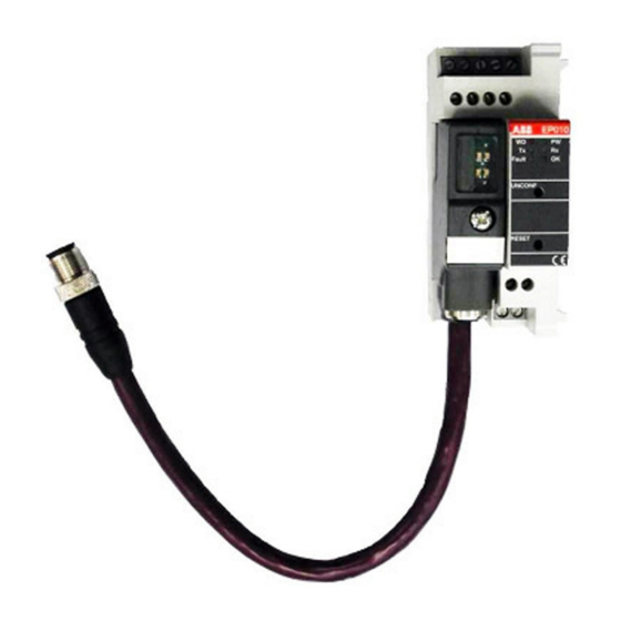
Figure 1. Terminals, indicators and operating
elements on the front plate ............................. 1
Figure 2. Dimensions for mounting ................. 2
TABLES INDEX
Table 1. Modbus port terminals ...................... 1
Table 2. Device communication parameters ... 2
Table 3. Start-up LEDs sequence ................... 3
Table 4. Normal LEDs behaviour .................... 3
Table 5. Diagnostic codes .............................. 4
Table 6. Troubleshooting ................................. 4
Figure 1. Terminals, indicators and operating elements on the front plate
TERMINAL NAME
MODBUS CABLE
L (left)
A
1 (right)
B
Table 1. Modbus port terminals
Total length of the Modbus cable from EP010 to connected device has to
be less or equal to 1 m.
EP010
1SDH000509R0001
N° Pag.
L3116
1/4

Related Manuals for ABB EP010


Summary of Contents for ABB EP010
- Page 1 This document describes the installation, use and disinstallation procedures of EP010 program further named as program. 7. Command not executed The command is correctly received by the EP010 but it’s not possible to For more information see document. n.1SDH000510R0001. send it to the device (e.g. the device is not connected).
- Page 2 After a failure has been detected and signalled, the FAULT LED continues flashing until: Dimensions for mounting refer to the following figure 1. the FBP is communicating with the EP010 (and then the EP010 is communicating with the device using the Modbus port) and the fault is removed OR Figure 2.