Table of Contents
Quick Links
Instruction Manual
Form 5777
September 2004
Type i2P-100 Electro-Pneumatic Transducers
Contents
. . . . . . . . . . . . . . . . . . . . . . . . . . . . . . .
. . . . . . . . . . . . . . . . . . . . . . . . . . .
. . . . . . . . . . . . . . . . . . . . . . . . . . . . . . . .
. . . . . . . . . . . . . . . . . . . . . . . . . . . . .
. . . . . . . . . . . . . . . . . . . . . . . . . . . . . . . .
. . . . . . . . . . . . . . . . . . . . . . . . . . . . . . . .
. . . . . . . . . . . . . . . . . . . . . . . . . . . . . . . . . . .
. . . . . . . . . . . . . . . . . . . . . . . . . . . . . . .
. . . . . . . . . . . . . . . . . . . . . . . . . . . . .
. . . . . . . . . . . . . . . . . . . . . . . . .
. . . . . . . . . . . . . . . . . . . . . . .
. . . . . . . . . . . . . . . . . . . . . . . . . . . .
. . . . . . . . . . . . . . . . . . . . . . . . . . . . . . . .
Introduction
Scope of Manual
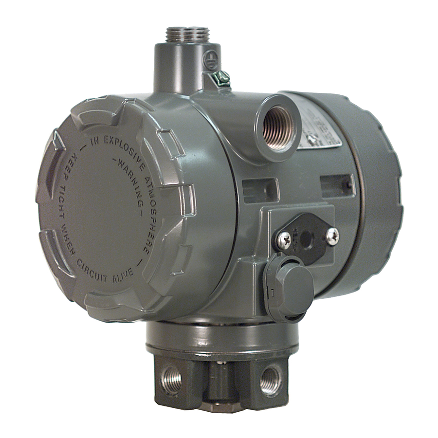
This instruction manual provides installation,
operation, maintenance, and parts ordering
information for the Type i2P-100 transducer (see
figure 1). Refer to separate manuals for instructions
covering equipment used with the transducer.
No person may install, operate or maintain a Type
i2P-100 electro-pneumatic transducer without
first D being fully trained and qualified in valve,
actuator and accessory installation, operation and
maintenance, and D carefully reading and
understanding the contents of this manual. If you
have any questions about these instructions, contact
your Fisher sales office.
. . . . . . . . . . . . . . . . . . . . . . .
. . . . . . . . . . . . . . . . . . . .
. . . . . . . . . . . .
. . . . . . . . . . . . . . . . . . .
. . . . . . . . . . . . . . . . . . . . .
. . . . . . . . . . . . . . . . . . . . . . .
. . . . . . . . . . . . . . . . . . . . .
. . . . . . . . . . . . . . . . . . . .
. . . . . . . . . . . . . . . . . . . . . .
. . . . . . . . . . . .
. . . . . . . . . . .
1
1
1
3
4
4
5
6
6
7
8
8
8
8
INTEGRAL
PNEUMATIC
9
RELAY
9
10
W8710
10
11
Figure 1. Type i2P-100 Electro-Pneumatic Transducer
11
11
12
Description
13
13
The transducer, shown in figure 3, receives a 4 to 20
milliampere dc input signal and transmits a
proportional user field-configurable pneumatic output
pressure to a final control element. The pneumatic
output ranges are typically 0.2 to 1.0 bar (3 to 15
psig) and 0.4 to 2.0 bar (6 to 30 psig). A typical
application is in electronic control loops where the
final control element is a control valve assembly that
is pneumatically operated. The input signal and
output pressure range of the transducer is indicated
on the nameplate, attached to the housing.
Dropping or rough handling of the
transducer can cause damage to the
converter module resulting in a shifted
output or a minimum output.
i2P-100 Transducer
VENT
CAUTION
REPLACEABLE
FILTER WITH
REMOVABLE
ORIFICE
Table of Contents

Related Manuals for Emerson i2P-100


Summary of Contents for Emerson i2P-100
-
Page 1: Table Of Contents
The input signal and operation, maintenance, and parts ordering output pressure range of the transducer is indicated information for the Type i2P-100 transducer (see figure 1). Refer to separate manuals for instructions on the nameplate, attached to the housing. - Page 2 Instruction Manual Form 5777 i2P-100 Transducer September 2004 Table 1. Specifications Input Signal Maximum Output Air Capacity 8.0 m /hr (5.0 scfm) at 1.4 bar (20 psig) supply Available as standard with 4 - 20 mA. pressure User configurable by dip switch for split ranging, see table below.
-
Page 3: Specifications
IEC 61000-4-5 I/O signal/control Conducted RF IEC 61000-4-6 Specification limit = ±1% of span Specifications Specifications for the Type i2P-100 transducer are listed in table 1. LOADING WARNING EXHAUSTING This product is intended for a specific current range, temperature range and other application specifications. -
Page 4: Educational Services
V300B Rotary Valve. Installation Figure 3. Type i2P-100 Electro-Pneumatic Transducer The i2P-100 transducer has been designed and Mounted on a Size 30 667 Sliding-Stem Actuator approved for use with either air or natural gas as the supply medium. In normal operation the unit will vent the supply medium into the surrounding atmosphere unless it is remotely vented. -
Page 5: Mounting
Instruction Manual Form 5777 i2P-100 Transducer September 2004 22.3 0.5 14 NPT 58.7 (0.88) CONDUIT (2.31) CONNECTION 0.25 18 NPT VENT OR PIPE-A-WAY 0.25 18 NPT CONNECTION 0.25 18 NPT OUTPUT OUTPUT CONNECTION CONNECTION 0.25 18 NPT 22.9 SUPPLY 67.8 33.3... -
Page 6: Pneumatic Connections
Instruction Manual Form 5777 i2P-100 Transducer September 2004 i2P-100 TRANSDUCER MOUNTING BRACKET REGULATOR Figure 6. Typical Type i2P- 100 Mounting With Type 67CFR Filter Regulator between the transducer output and the final control Supply Pressure Requirements element should be as short as possible. Transducer overall dimensions are shown in figure 5. -
Page 7: Diagnostic Connections
GAUGE BODY PROTECTOR BODY PIPE BUSHING GE06439-A (sheet 1 of 4) PIPE TEE B2395-1/IL PIPE NIPPLE Figure 7. Diagnostics Hookup for Type i2P-100 Transducer Diagnostic Connections TRANSDUCER TERMINAL BLOCK HOUSING To support diagnostic testing of valve/actuator/positioner packages, special CONTROL FIELD WIRING connectors and hardware are available. -
Page 8: Vent
Operating Information reduce case pressure buildup. The normal mode of operation for Type i2P-100 If a remote vent is required, the vent line must be as transducer requires that the pneumatic output short as possible with a minimum number of bends pressure be piped to the final control element. -
Page 9: Equipment Required
Instruction Manual Form 5777 i2P-100 Transducer September 2004 PCB/CUP ZERO ASSEMBLY ADJUSTMENT 4-12 , 3-15 12-20 , 3-15 4-20 , 3-15 4-20 , 6-30 SPAN ADJUSTMENT SWITCH (1,2) SETTINGS FIELD WIRING CONNECTION NOTES: GE03345 1. INPUT SIGNAL SPLIT RANGE IS SELECTABLE VIA DIP-SWITCH CONFIGURATION. -
Page 10: Principle Of Operation
Maintenance The normal mode of operation for Type i2P-100 transducer requires that the pneumatic output CAUTION pressure be piped to the final control element. If this... -
Page 11: Troubleshooting
Instruction Manual Form 5777 i2P-100 Transducer September 2004 in this manual. Improper techniques 4. Force the converter module to maximum output can cause poor quality repairs and pressure with a 30 milliampere dc signal. Output impair the safety features of the pressure should build up to the approximate value of device. -
Page 12: Relay Maintenance
Instruction Manual Form 5777 i2P-100 Transducer September 2004 Relay Maintenance VALVE PLUG (KEY 39) Refer to figures 12 and 14 for key number locations. ONE OF THREE Removal TABS ON VALVE PLUG 1. Remove the four mounting screws (key 36, shown in figure 14) and remove the relay from the transducer. -
Page 13: Parts Ordering
Instruction Manual Form 5777 i2P-100 Transducer September 2004 6. When replacing the input diaphragm (key 38), Note make sure all passages and screw holes are aligned. Place the input diaphragm on the body Fisher does not assume responsibility block (key 40). Hold assembled parts in place. - Page 14 Instruction Manual Form 5777 i2P-100 Transducer September 2004 NOTE: APPLY LUBRICANT/SEALANT/ADHESIVE 30C2230-A / IL Figure 13. Type i2P- 100 Transducer Assembly PWB/Cup Assembly I/P Converter Assembly PWB/Cup Assembly GE10168X012 I/P Converter Assembly 30C2218X012 Machine Screw (2 req’d) GE11776X012 Machine Screw...
- Page 15 Note 480 Series actuator boss Mounting Bracket, steel 3P426825022 If the Type i2P-100 Transducer is used in a Washer, steel pl (4 req’d) 1B865928982 valve assembly with a positioner, no hook-up Cap Screw, steel pl (4 req’d)
-
Page 16: Www.fisher.com
FlowScanner and Fisher are marks owned by Fisher Controls International LLC, a member of the Emerson Process Management business division of Emerson Electric Co. The Emerson logo is a trademark and service mark of Emerson Electric Co. All other marks are the property of their respective owners.