Table of Contents
Quick Links
HARDWARE MANUAL [CONNECTION]
GOT-F900 SERIES GRAPHIC OPERATION TERMINAL
Covered models
F920GOT-K
F920GOT-BBD-K-E
F920GOT-BBD5-K-E
F930GOT(-K)
F930GOT-BWD-E
F930GOT-BBD-K-E
F940GOT
F940WGOT-TWD-E
F940GOT-SWD-E/-LWD-E
Handy GOT
F940GOT-SBD-H-E/-LBD-H-E
F943GOT-SBD-H-E/-LBD-H-E
F940GOT-SBD-RH-E/-LBD-RH-E
F943GOT-SBD-RH/-E-LBD-RH-E
Screen creation software
GT Designer2
(SW*D5C-GTD2-E)
GT Designer
(SW*D5C-GOTR-PACKE)
FX-PCS-DU/WIN-E
Table of Contents
Troubleshooting

Related Manuals for Mitsubishi Electric F920GOT-K


Summary of Contents for Mitsubishi Electric F920GOT-K
- Page 1 HARDWARE MANUAL [CONNECTION] GOT-F900 SERIES GRAPHIC OPERATION TERMINAL Covered models Screen creation software F920GOT-K GT Designer2 F920GOT-BBD-K-E (SW*D5C-GTD2-E) F920GOT-BBD5-K-E GT Designer F930GOT(-K) (SW*D5C-GOTR-PACKE) F930GOT-BWD-E FX-PCS-DU/WIN-E F930GOT-BBD-K-E F940GOT F940WGOT-TWD-E F940GOT-SWD-E/-LWD-E Handy GOT F940GOT-SBD-H-E/-LBD-H-E F943GOT-SBD-H-E/-LBD-H-E F940GOT-SBD-RH-E/-LBD-RH-E F943GOT-SBD-RH/-E-LBD-RH-E...
- Page 2 GOT-F900 SERIES GRAPHIC OPERATION TERMINAL. It should be read and understood before attempting to install or use the unit. • Further information can be found in the GOT-F900 Operation Manual, F920GOT-K Installation Manual, F930GOT Installation Manual, F930GOT-K Installation Manual, F940GOT Installation Manual, F940WGOT Installation Manual.
- Page 3 GOT-F900 SERIES (CONNECTION) GOT-F900 SERIES GRAPHIC OPERATION TERMINAL HARDWARE MANUAL (CONNECTION) Manual number : JY992D94801 Manual revision : C Date : MARCH 2003...
- Page 4 GOT-F900 SERIES (CONNECTION)
- Page 5 Mitsubishi users are always welcomed. This page has been designed for you, the reader, to fill in your comments and fax them back to us. We look forward to hearing from you. Fax numbers: Your name: ........... Mitsubishi Electric................. America (01) 847-478-2253 Your company: ..........
- Page 6 GOT-F900 SERIES (CONNECTION)
- Page 7 GOT-F900 SERIES (CONNECTION) Guidelines for the Safety of the User and Protection of the Graphic operation terminal GOT-F900 This manual provides information for the use of the Graphic operation terminal GOT-F900. The manual has been written to be used by trained and competent personnel. The definition of such a person or persons is as follows;...
- Page 8 GOT-F900 SERIES (CONNECTION) • Under no circumstances will Mitsubishi Electric be liable responsible for any consequential damage that may arise as a result of the installation or use of this equipment. • All examples and diagrams shown in this manual are intended only as an aid to understanding the text, not to guarantee operation.
-
Page 9: Table Of Contents
4.4.2 Inner dimension of the panel required for installation..........4-10 4.4.3 Installation procedure ....................4-13 4.5 Connector Pin Layout and Signal Name (Excluding the 5 V type F920GOT-K.)4-14 4.6 Outline of Internal Wiring ................... 4-15 4.7 Wiring for 24V DC and 5V DC Power Supply and Class D Grounding....4-16 4.8 Handling of Function Keys (F1 to F8) (F920GOT-K and F930GOT-K) ..... - Page 10 GOT-F900 SERIES (CONNECTION) Contents 5. Installation and Wiring of Handy GOT ............5-1 5.1 Outline of Connection ..................5-5 5.1.1 Handy GOT (Excluding RH model) ................5-5 5.1.2 Handy GOT (RH model) .................... 5-7 5.2 Name of Each Part ....................5-8 5.2.1 Front Panel ........................
- Page 11 8.3.2 Devices which can be monitored................8-6 8.3.3 When GOT-F900 is connected to optional port ............8-6 8.3.4 Restrictions in connecting two or more F920GOT-K (5V type) units to FX Series PLC ........................... 8-9 8.4 Setting of Connected Equipment for GOT ............8-10 8.5 Cable Diagram....................
- Page 12 GOT-F900 SERIES (CONNECTION) Contents 9. Connection of MELSEC-A Series PLC ............9-1 9.1 System Condition ....................9-2 9.2 System Configuration ..................9-2 9.2.1 Configuration for Direct Connection (RS-422)............9-3 9.2.2 Configuration for A Computer Link Connection (RS-422) ......... 9-5 9.2.3 Configuration for A Computer Link Connection (RS-232C)........9-7 9.3 Setting in A Computer Link Connection...............
- Page 13 GOT-F900 SERIES (CONNECTION) Contents 12.Connection of FX Series Positioning Unit (FX -10/20GM).......12-1 (2N) 12.1 System Condition ....................12-1 12.2 System Configuration ..................12-2 12.2.1 Configuration for GMCPU direct connection (RS-422)..........12-2 12.3 Cautions on use of FX Series positioning unit ........... 12-4 12.3.1 Device specification....................
- Page 14 14.6.4 Fill Command ......................14-22 14.6.5 Interrupt Code ....................... 14-22 14.7 Caution on Use of Microcomputer Connection ..........14-23 14.7.1 When Using F920GOT-K ..................14-23 14.8 Setting of Connected Equipment for GOT ............14-24 14.9 Cable Diagram....................14-31 14.10Troubleshooting ....................14-33 14.11BASIC Program Example ................
- Page 15 GOT-F900 SERIES (CONNECTION) Contents 18.Connection of FP Series PLC (Manufactured by Matsushita Electric Works)18-1 18.1 System Condition ....................18-2 18.1.1 Classification of Product Names ................18-2 18.2 System Configuration ..................18-3 18.2.1 Configuration for CPU Direct Connection (RS-232C)..........18-3 18.3 Setting of Series ....................18-5 18.3.1 Communication Setting Specifications ..............
- Page 16 23.3.4 Cautions on Use of FX-2PIF ................. 23-17 23.3.5 Cable Diagram ...................... 23-18 23.4 GOT-F900 Connector Signal Correspondence Table (Excluding the 5V type F920GOT-K.) .............. 23-19 23.4.1 RS-422 Correspondence Table ................23-19 23.4.2 RS-232C Correspondence Table ................. 23-19 23.5 Error Messages in GOT-F900 Series .............. 23-20...
-
Page 17: Introduction
GOT-F900 SERIES (CONNECTION) Introduction 1 Introduction We appreciate it very much that you have purchased Mitsubishi graphic operation terminal. Please read thoroughly this manual to understand sufficiently and use correctly the functions and the performance of the graphic operations terminal. Please make sure that this manual is delivered to the end user. - Page 18 Device Names Which can be Monitored ↓ ↓ ↓ ↓ This manual can be classified as follows in accordance with the type of GOT-F900 Series. F920GOT-K, F930GOT(-K), F940GOT or F940WGOT Series........Read from Section 3. Handy GOT Series....................Read from Section 4.
-
Page 19: Classification Of Manuals In Accordance With Purpose
When requiring a manual not included with the product, contact our sales representative. COMMON HARDWARE MANUAL (sent separately) Corresponds to all of the F920GOT-K, F930GOT(-K), F940GOT and handy GOT Series, and describes in details the connection to a PLC or personal computer and the setting method. - Page 20 09R811 OPERATION MANUAL of GOT (sent separately) Describes how to operate system screens and how to create and operate user screens, and covers all of the F920GOT-K, F930GOT(-K), F940GOT and Handy GOT. • GOT-F900 SERIES OPERATION MANUAL (No. JY992D94701) To learn the display function of the GOT-F900.
- Page 21 GOT-F900 SERIES (CONNECTION) Introduction 1 • GOT-F900 SERIES OPERATION MANUAL [GT Designer2] (No. JY997D09101) To learn the display function of the GOT-F900. Applicable GOT To execute items in the HPP mode (such as F920GOT-BBD-K-E F920GOT-BBD5-K-E "PROGRAM LIST" and "MONITOR"). F930GOT-BWD-E To execute "DEVICE MONITOR"...
- Page 22 GOT-F900 SERIES (CONNECTION) Introduction 1 • FX-PCS-DU/WIN-E OPERATION MANUAL (No: JY992D68301) To install the software to the personal computer. To start up the software. To learn how to connect the personal computer to the It is included with the GOT. FX-PCS-DU/WIN-E.
-
Page 23: Abbreviations, Generic Names And Terms Used In This Manual
Abbreviations, generic names and terms used in this manual are shown below. 1.2.1 Types and Names of GOT-F900 Series F940GOT F930GOT Handy GOT P O W E R F930GOT-K F920GOT-K G R I P S W P O W E R Generic Name Model name Built-in I/F Remarks... -
Page 24: Information Offered By Model Name
GOT-F900 SERIES (CONNECTION) Introduction 1 1.2.2 Information Offered by Model Name F9"""GOT-####-#-#-# 1) 2) 4) 5) 6) 7) 1) LC display size 2: 3 in. 3: 4 in. 4: 6 in. (7 in. in F940WGOT) 2) PLC connection specifications 0: RS-422,RS-232C Interface 3: RS-232C ×... -
Page 25: In-Built Fonts Of Graphic Operation Terminal (Japanese/Overseas Product)
GOT-F900 SERIES (CONNECTION) Introduction 1 1.2.3 In-built Fonts of Graphic Operation Terminal (Japanese/Overseas product) Carefully confirm the in-built fonts when selecting a model from the F920GOT-K or F930GOT(-K). In-built fonts (user screen) Language displayed on system screen Japanese English Korean Chinese... -
Page 26: Abbreviation List
GOT-F900 SERIES (CONNECTION) Introduction 1 1.2.4 Abbreviation List Abbreviation/generic name/term Description Generic name of Q00JCPU, Q00CPU, Q01CPU, Q02CPU, Q02HCPU, QCPU(Q mode) Q06HCPU, Q12HCPU and Q25HCPU units QCPU(A mode) Generic name of Q02CPU-A, Q02HCPU-A and Q06HCPU-A units QCPU Generic name of QCPU (Q mode) and QCPU (A mode) units Generic name of Q2ACPU, Q2ACPU-S1, Q3ACPU, Q4ACPU and QnACPU(large type) Q4ARCPU units... - Page 27 GOT-F900 SERIES (CONNECTION) Introduction 1 Abbreviation/generic name/term Description PLC by PLC by another Generic name of PLC manufactured by Omron, Fuji Electric, Yasukawa other company Electric, Allen-Bradley or Siemens companies Abbreviation of GOT system software Abbreviation of screen creation software for GOT-A900/GOT-F900 Series Integrated screen development software SW"D5C- for GOT900 Series (SW"D5C-GTD2-E +...
- Page 28 GOT-F900 SERIES (CONNECTION) Introduction 1 Abbreviation/generic name/term Description Black White Yellow Brown Blue Gray Connection Orange diagram Purple Pink Fresh green Sky blue Green 1-12...
-
Page 29: Outline
The table below shows connection types supported by the GOT-F900 having the lastest OS version. 2.1.1 GOT type list and index Connection Connected equipment Description Reference destination F920GOT-K, Name of each part, installation and power supply − F930GOT, F930GOT-K, Chapter 4 wiring F940GOT, F940WGOT Dedicated wiring and functions of Handy GOT such −... -
Page 30: Connection Type List And Index
GOT-F900 SERIES (CONNECTION) Outline 2 2.1.2 Connection type list and index " " indicates can connect. "−" indicates cannot connect. Transmission Connection Connected Connection specifications of two or Manufacturer Reference equipment destination more GOT RS-422 RS-232C units FX Series CPU direct connection Chapter 8 −... -
Page 31: Outline Of Connection Types
B a r c o d e r e a d e r G O T - . 9 0 0 c o m p u t e r ( o n l y i n . X / . X / . X *1 Excluding the F920GOT-K... - Page 32 / . X / . X 2 N C *1 Excluding the 5V type F920GOT-K. *2 Excluding the F920GOT-K 3) Connection of two or more GOT units Up to four GOT-F900 units can be connected to the programming port or the optional communication port of the FX Series PLC.
- Page 33 S e r i e s ) *1 Excluding the F920GOT-K *2 Excluding the 5V type F920GOT-K. 2) CPU direct connection (RS-232C) GOT-F900 is connected to the programming por t of the Q Series PLC (Multi-CPU system applicable ) or the serial communication unit of the Q/QnA Series PLC.
- Page 34 P r i n t e r r e a d e r M E L S E C - A S e r i e s *1 Excluding the 5V type F920GOT-K. *2 Excluding the F920GOT-K. 4) Connection of two or more GOT units In the A/QnA Series PLC, up to four GOT-F900 units can be connected to programming ports (RS- 422) of the CPU.
-
Page 35: Plc By Other Companies
*1 Excluding the 5V type F920GOT-K. *2 Excluding the F920GOT-K. 2) Connection of two or more GOT units Up to four GOT-F900 units can be connected to the serial communication connector of a personal computer or microcomputer board. - Page 36 B a r c o d e r e a d e r . P 2 - C C U G O T - . 9 0 0 *1 Excluding the 5V type F920GOT-K. *2 Excluding the F920GOT-K. PLC by Allen-Bradley CPU direct connection (RS-232C) One GOT-F900 unit can be connected to the SLC500/MicroLogix Series CPU.
-
Page 37: Others
R S - 2 3 2 C P r i n t e r G O T - . 9 0 0 *1 Excluding the F920GOT-K and Handy GOT Bar code reader Connection of bar code reader When a bar code reader is connected to the GOT-F900, bar codes can be read. - Page 38 GOT-F900 SERIES (CONNECTION) Outline 2 MEMO 2-10...
-
Page 39: Specifications
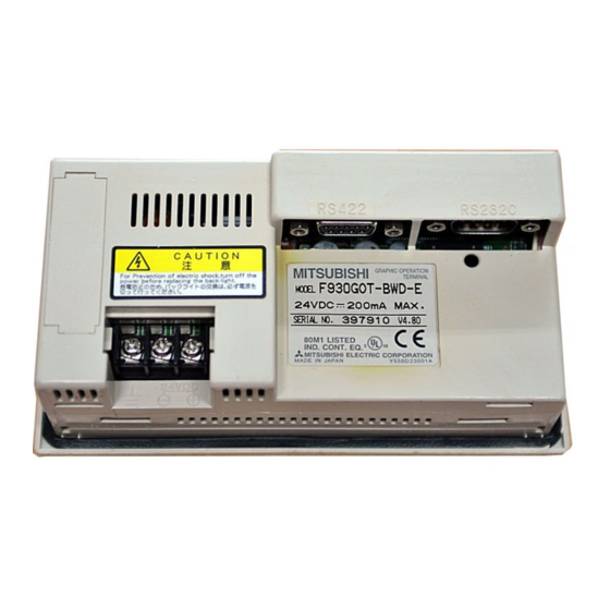
Copyright(C) 1998 Ver.2.10 Version Mitsubishi Electric Corporation On the rear panel of the GOT-F900 main unit, the nameplate indicating the manufacturer's serial number, the model name and the OS version is adhered. However, because the OS can be upgraded, it... -
Page 40: Plc, Positioning Unit, Inverter Manufactured By Mitsubishi
Connection of two Reference 940W name RS-422 or more GOT units system system system system MITSUBISHI Electric MELSEC-F FX Series (CPU direct connection) Connection type name [FXCPU direct connection] Connection to programming port in FX CPU FX,FX 1.00 1.00 1.00 1.00 -422-BD RS-422 8.2.1... - Page 41 1.10 6.10 4.10 A500 Series (PU port, FR-A5NR) RS-422 13.2.1 or later or later or later E500 Series (PU port) $: Can connect : Cannot connect *1 Excluding the 920 system *2 Excluding the 5 V type F920GOT-K.
-
Page 42: Plc Manufactured By Other Companies
GOT-F900 SERIES (CONNECTION) Specifications 3 3.1.3 PLC Manufactured by Other Companies The table below describes the product evaluated in each series. OS version RS-232C/ Connection of two Connected equipment name and series name Reference 940W RS-422 or more GOT units system system system... - Page 43 FPG-C32T+FPG-COM1 (port 1) 1.62 6.62 4.62 1.20 RS-232C FPG-C32T+FPG-COM2 (port 1, port 2) or later or later or later or later : Cannot connect $: Can connect *1 Excluding the 920 system *2 Excluding the 5 V type F920GOT-K.
-
Page 44: Others
: Cannot connect $: Can connect *1 Excluding the 920 system *2 Excluding the 5 V type F920GOT-K. 3.1.4 Others The table below describes the product evaluated in each series. OS version Connected equipment name and series... -
Page 45: Version Of Screen Creation Software And Correspondence To Got-F900
GOT-F900 SERIES (CONNECTION) Specifications 3 Version of Screen Creation Software and Correspondence to GOT-F900 Three types of screen creation software are offered the SW"DSC-GTD2-E, SW"D5C-GOTR-PACKE and FX-PCS-DU/WIN-E as follows. Types of screen creation software Screen creation software Name Generic name SW"D5C-GTWS-E SW"D5C-GTWK2-E GT Designer2... -
Page 46: How To Conform Version Of Screen Creation Software
GOT-F900 SERIES (CONNECTION) Specifications 3 3.2.1 How to Conform Version of Screen Creation Software You can confirm the version by displaying the help screen after starting up the screen creation software in the personal computer or by confirming the contents indicated on the FD or CD-ROM of the product. 1) When confirming the version using the help function of the software For the GT Designer2, GT Designer and DU/WIN, you can confirm the version by selecting [Help (H)]-[About (A)] from the menu bar. - Page 47 GOT-F900 SERIES (CONNECTION) Specifications 3 2) When confirming the version through the contents indicated on the media You can confirm the version by checking the contents indicated on the media of the product. a) GT Designer2 (CD-ROM) MITSUBISHI DATE A version MELSEC 9812AA (An alphabet at the end indicates the small version.)
-
Page 48: Screen Creation Software Version Corresponding To Got-F900 Series
− F930GOT-K SW1-A (1.00A) SW5-26C (5.26C) F930GOT SW1-A (1.00A) SW1-H 2.20 F933GOT SW1-A (1.00A) SW1-H 2.20 F920GOT-K (5V) SW1-A (1.00A) SW5-26C (5.26C) 2.70 − − F920GOT-K (24V) SW1-C (1.02C) F940 Handy GOT SW1-A (1.00A) SW1-D 2.10 F940 Handy GOT (RH model) SW1-A (1.00A) -
Page 49: Screen Creation Software Corresponding To Each Connected Equipment
GOT-F900 SERIES (CONNECTION) Specifications 3 3.2.3 Screen Creation Software Corresponding to Each Connected Equipment Products in Japanese SW" " " " D5C-GTD2-J SW" " " " D5C-GOTR-PACK FX-PCS-DU/WIN Connected equipment (abbreviation) Version Version Version Mitsubishi FXCPU direct connection ACPU direct connection SW1-A (1.00A) SW1-A 2.00... - Page 50 GOT-F900 SERIES (CONNECTION) Specifications 3 Products in English SW" " " " D5C-GOTR- FX-PCS-DU/WIN-E SW" " " " D5C-GTD2-E Connected equipment (abbreviation) PACKE Version Version Mitsubishi FXCPU direct connection SW1-C (1.02C) ACPU direct connection SW1-C (1.02C) SW1-E 2.00 A computer link SW1-C (1.02C) QnACPU direct connection SW1-C (1.02C)
-
Page 51: Device Names Which Can Be Monitored
Not to be used F930GOT-K Ver. 4.60 or later (From first product) GD100 to GD1023 For user's use F920GOT-K Ver. 1.00 or later (From first product) Handy GOT Ver. 6.40 or later *2 Which cannot be input or changed 3-13... -
Page 52: Plc By Mitsubishi
In specifying word devices for the bar code reader, C200 to C255 and CS200 to CS255 are not available. *1 GB132 to GB255 and GD100 to GD127 in the F920GOT-K *2 In data changes, the condition shown below is present. - Page 53 GOT internal data register (GD) *1 Latch relays (L) are treated as internal relays (M) in the GOT-F900. *2 GB132 to GB255 and GD100 to GD127 in the F920GOT-K *3 In data changes, the condition shown below is present. Condition enabling data changes...
- Page 54 GD100~GD1023 GOT internal data register (GD) *1 GB132 to GB255 and GD100 to GD127 in the F920GOT-K *2 File registers in a block changed over by the RSET instruction are regarded as targets. Restriction in set monitor in computer link for A Series...
- Page 55 GOT-F900 SERIES (CONNECTION) Specifications 3 Specification of PLC number when using Q multiple PLC system Specify the PLC number when appointing the device. 0: CPU connected (Control PLC if connected to the link) 1 to 4: CPU with the specified number 3-17...
- Page 56 GOT-F900 SERIES (CONNECTION) Specifications 3 4) FX Series GM positioning unit (GM direct connection) Setting range Device Device name number GT Designer (2) DU/WIN representation Input (X) X0~X377 X0~X377 Octal Output (Y) Y0~Y67 Y0~Y67 Internal relay (M) M0~M511 M0~M511 device Special auxiliary relay (SM) M9000~M9175 M9000~M9175...
- Page 57 GOT-F900 SERIES (CONNECTION) Specifications 3 5) FREQROL Series inverter (INV direct connection) Setting range Device Device name number GT Designer (2) DU/WIN representation Control status (S) S0:"~S7:" device GOT internal bit register (GB) GB132~1023 Alarm code (A) A0:"~A7:" Parameter (Pr) Pr0:"~Pr993:"...
-
Page 58: Plc Units Manufactured By Other Companies
*2 The special memory is offered for special application (such as interrupt output and communication error information) in the GOT. *3 In the F920GOT-K, D0 to D1023 are available. *4 GB132 to GB255 and GD100 to GD127 in the F920GOT-K 2) SYSMAC C Series manufactured by Omron Setting range... - Page 59 GOT-F900 SERIES (CONNECTION) Specifications 3 3) FLEX-PC N Series manufactured by Fuji Electric Setting range Device Device name number GT Designer2 DU/WIN representation Input (X) X0~X7FF X0~X7FF Output (Y) Y0~Y7FF Y0~Y7FF M0~M1FFF M0~M1FFF Internal relay (M) L0~L1FFF L0~L1FFF Latch relay (L) device State (S) S0~S7FF...
- Page 60 However, access is disabled in special data registers from D90000 in the FP Series. *5 Access is enabled only in the bank 0. *6 Bit device number (3-digit decimal number) + Bit position (1-digit hexadecimal number) *7 GB132 to GB255 and GD100 to GD127 in the F920GOT-K 3-22...
- Page 61 GOT-F900 SERIES (CONNECTION) Specifications 3 6) SLC500/MicroLogix Series manufactured by Allen-Bradley a) SLC500 Series i) GT Designer (earlier than Version 5.05F) and DU/WIN (earlier than Version 2.50) Setting range Device Device name number GT Designer DU/WIN representation B0030000~B003255F B0030000~B003255F Bit (B) Hexadecimal B0100000~B255255F B0100000~B255255F...
- Page 62 GOT internal data register (GD) *1 32 bits cannot be specified. *2 GB132 to GB255 and GD100 to GD127 in the F920GOT-K File number and element specification range Specify the file number and an element in decimal numbers. However, specify the bit position of a bit (B) in a hexadecimal number.
- Page 63 GOT internal data register (GD) *1 32 bits cannot be specified. *2 GB132 to GB255 and GD100 to GD127 in the F920GOT-K File number and element specification range Specify the file number and an element in decimal numbers. However, specify the bit position of a bit (B) in a hexadecimal number.
- Page 64 GOT-F900 SERIES (CONNECTION) Specifications 3 7) S7-200/300 Series manufactured by Siemens a) S7-200 Series Setting range Device Device name number GT Designer (2) FX-PCS-DU/WIN representation Variable Memory (V) V00~V51197 V0.0~V5119.7 Input (I) I00~I77 I0.0~I7.7 Output (Q) Q00~Q77 Q0.0~Q7.7 Bit memory (M) M00~M317 M0.0~M31.7 Special Memory (SM)
- Page 65 """ indicates a number in the range from 1 to 1023. Only even values are available as byte addresses of data register (DBW values). *1 GB132 to GB255 and GD100 to GD127 in the F920GOT-K Note on number representation A decimal point exists when using the GT Designer (2) but not when using the DU/WIN.
-
Page 66: Hardware Specifications
GOT-F900 SERIES (CONNECTION) Specifications 3 Hardware Specifications This section explains the hardware specifications of the GOT-F900 Series. 1) General specifications "o" of the GOT model name indicates 0 or 3. Item F940WGOT F940GOT F930GOT-K Product model name F940WGOT-TWD-E F940GOT-SWD-E F940GOT-LWD-E F930GOT-BBD-K-E 24V DC+10%-15% Supply voltage... - Page 67 GOT-F900 SERIES (CONNECTION) Specifications 3 F930GOT F920GOT-K Handy GOT F930GOT-BWD-E F920GOT-BBD-K-E F920GOT-BBD5-K-E F940GOT-SBD-(R)H-E F940GOT-LBD-(R)H-E 5V DC 24V DC+10%-15% Supplied from PLC (separately prepared DC power supply) 80mA/24V DC 220mA/5V DC 300mA/24V DC 200mA/24V DC (70mA/24V DC) (180mA/5V DC) (200mA/24V DC) −...
- Page 68 *1 The buzzer sounds as its power input from the outside of the GOT. When a touch key on the screen is pressed, the built-in buzzer sounds. (The in-built buzzer of F920GOT-K sounds only when the key-pad is operated.) 2) External interface specifications "o"...
- Page 69 GOT-F900 SERIES (CONNECTION) Specifications 3 F930GOT F920GOT-K Handy GOT F94" " " " GOT-SBD-H-E F94" " " " GOT-SBD-RH-E F920GOT-BBD-K-E F930GOT-BWD-E F94" " " " GOT-LBD-H-E F94" " " " GOT-LBD-RH-E F920GOT-BBD5-K-E a contact 4 switches a contact 4 switches 10 mV/24V DC −...
- Page 70 GOT-F900 SERIES (CONNECTION) Specifications 3 MEMO 3-32...
-
Page 71: Installation And Wiring Of F920Got-K/F930Got(-K)/F940(W)Got
F930GOT/F940(W)GOT may be caused. • Never drop cutting chips and electric wire chips into the ventilation window of the F920GOT-K/ F930GOT(-K)/F940(W)GOT when you drill screw holes or perform the wiring work. Otherwise, fire, failure or malfunction may be caused. - Page 72 Use solderless terminals for M3, and tighten them securely with the tightening torque of 0.5 to 0.8 N•m so that troubles are not caused. Index of each part For the F920GOT-K, F930GOT(-K) and F940WGOT, refer to corresponding sections and paragraphs shown below. (examples: F940GOT and F930GOT-K)
- Page 73 Name of each Part You can learn the name of each part of the F930GOT/F940(W)GOT. Processing of Panel Face You can learn the dimension of the processing on the panel face. You can learn the method to install the F920GOT-K/F930GOT/F930GOT- Installation K/F940(W)GOT.
-
Page 74: Outline Of Connection
*1 Because the F940WGOT consumes much current, it cannot be connected to the service power supply of the PLC. Prepare an external power supply. *2 The cable to connect the 5V type F920GOT-K to the FX, FX , A, QnA and Q Series PLC needs to be... -
Page 75: Name Of Each Part
F940WGOT 2 4 V D C 1) Power terminals: Supply the power to the GOT-F900 and perform the grounding. (Excluding the 5 V type F920GOT-K.) 2) Battery: Stores the sampling data, the alarm history and the current time. The screen data is stored in the built-in flash memory, and kept stored even if the life of the battery is expired. -
Page 76: Function Of Ports
1) PLC port (RS-422) 9-pin D-Sub, female Connect here a PLC through RS-422. Use this port also to connect two or more GOT units (through RS-422). (excluding the F920GOT-K) 2) Personal computer/PLC port (RS-232C) 9-pin D-Sub, male Connect here a personal computer to transfer the screen data created by the screen creation software. - Page 77 GOT-F900 SERIES (CONNECTION) Installation and Wiring of F920GOT-K/F930GOT(-K)/F940(W)GOT 4 4) Personal computer port (RS-232C) 9-pin D-Sub, male Connect here a personal computer to transfer the screen data created by the screen creation software. This port is not available to connect a PLC.
-
Page 78: Outside Dimensions And Panel Face Processing
GOT-F900 SERIES (CONNECTION) Installation and Wiring of F920GOT-K/F930GOT(-K)/F940(W)GOT 4 Outside Dimensions and Panel Face Processing This paragraph explains the specifications of outside dimensions of the GOT-F900, and the panel cut dimensions in processing the panel face. 4.3.1 Panel Cut Dimension On the panel face, drill an installation hole of the dimension shown below. -
Page 79: Installation
GOT-F900 SERIES (CONNECTION) Installation and Wiring of F920GOT-K/F930GOT(-K)/F940(W)GOT 4 Installation This section explains the caution on installation of the GOT-F900 on the panel face as well as the installation procedure. 4.4.1 Caution on installation When installing the GOT on the control panel, etc., make sure that the display unit is set at an angle shown in the figure below. -
Page 80: Inner Dimension Of The Panel Required For Installation
GOT-F900 SERIES (CONNECTION) Installation and Wiring of F920GOT-K/F930GOT(-K)/F940(W)GOT 4 4.4.2 Inner dimension of the panel required for installation When installing the GOT, take into consideration the inner dimension shown below. a) PLC cable b) Packing Dimensions: mm (inches) F920GOT-K 109(4.29)(metal fixture external shape) 168(6.61) - Page 81 GOT-F900 SERIES (CONNECTION) Installation and Wiring of F920GOT-K/F930GOT(-K)/F940(W)GOT 4 F940GOT 5 7 ( 2 . 2 4 ) L a t e r a l i n s t a l l a t i o n 2 4 V D C 1 5 2 ( 5 .
- Page 82 GOT-F900 SERIES (CONNECTION) Installation and Wiring of F920GOT-K/F930GOT(-K)/F940(W)GOT 4 F940WGOT 7 0 . 6 ( 2 . 7 8 ) L a t e r a l i n s t a l l a t i o n 2 0 5 ( 8 . 0 7 ) 5 ( 0 .
-
Page 83: Installation Procedure
GOT-F900 SERIES (CONNECTION) Installation and Wiring of F920GOT-K/F930GOT(-K)/F940(W)GOT 4 4.4.3 Installation procedure The GOT-F900 is so designed as to be embedded in the panel. Install the GOT using the procedure shown below. For the panel cut dimension, refer to the previous page. -
Page 84: Connector Pin Layout And Signal Name (Excluding The 5 V Type F920Got
GOT-F900 SERIES (CONNECTION) Installation and Wiring of F920GOT-K/F930GOT(-K)/F940(W)GOT 4 Connector Pin Layout and Signal Name (Excluding the 5 V type F920GOT-K.) The figure below shows the pin layout in the serial interface connector built in the GOT-F900. F920GOT-K (24 V type)/F930GOT/F930GOT-K/F940GOT/F940WGOT... -
Page 85: Outline Of Internal Wiring
GOT-F900 SERIES (CONNECTION) Installation and Wiring of F920GOT-K/F930GOT(-K)/F940(W)GOT 4 Outline of Internal Wiring The figure below shows the internal wiring of the GOT-F900. F920GOT-K/F930GOT-K Display circuit The 24V type LCD panel Power F920GOT-K and supply F930GOT-K circuit Touch switch circuit... -
Page 86: Wiring For 24V Dc And 5V Dc Power Supply And Class D Grounding
GOT-F900 automatically displays the title screen and then an user screen. 3) Electric wires to be used (excluding only the 5 V type F920GOT-K) Use electric wires of 0.75mm or more in the wiring of the power supply so that voltage drop does not occur. - Page 87 Install wiring from 24V DC power supply and grounding to the terminal block on the rear panel of the GOT-F900. No wiring is required because power is supplied to the F920GOT-K via a communication cable. . 9 3 0 G O T , . 9 3 3 G O T...
- Page 88 1 0 0 W o r l e s s a) Example when the power is supplied from the PLC Connect the power terminal of the F920GOT-K (24V type)/F930GOT/F930GOT-K/F940GOT to the 24V DC service power supply of the PLC or extension unit.
-
Page 89: Handling Of Function Keys (F1 To F8) (F920Got-K And F930Got-K)
GOT-F900 SERIES (CONNECTION) Installation and Wiring of F920GOT-K/F930GOT(-K)/F940(W)GOT 4 Handling of Function Keys (F1 to F8) (F920GOT-K and F930GOT-K) The ON/OFF status of the function keys is transmitted to the PLC via a communication cable. Allocation of keys F920GOT-K F930GOT-K... -
Page 90: Use Of Function Keys
GOT-F900 SERIES (CONNECTION) Installation and Wiring of F920GOT-K/F930GOT(-K)/F940(W)GOT 4 4.8.1 Use of function keys This section explains the use of the function keys and the indicator LEDs (only in the F930GOT-K). 1) Wiring of function keys No wiring of the function keys is required because the keys and the connected equipment (PLC) communicate via a communication cable. -
Page 91: Preparation Of Function Key Name Sheet (Available In The F930Got-K)
GOT-F900 SERIES (CONNECTION) Installation and Wiring of F920GOT-K/F930GOT(-K)/F940(W)GOT 4 4.8.2 Preparation of Function Key Name Sheet (Available in the F930GOT-K) This section explains how to prepare the function key name sheet. 1) Preparing the name sheet a) Make the mount sheet in reference to the following dimensions and prepare an OHP sheet (transparent and colorless sheet). -
Page 92: Cautions On Use
GOT-F900 SERIES (CONNECTION) Installation and Wiring of F920GOT-K/F930GOT(-K)/F940(W)GOT 4 4.8.3 Cautions on use With regard to the function keys (Operation Panel), the priority is given to the base screen and overlap windows. If there are two or more types of setting, only the setting on a screen having higher priority is valid in the unit of function key No. -
Page 93: Label Pattern (F930Got-K)
GOT-F900 SERIES (CONNECTION) Installation and Wiring of F920GOT-K/F930GOT(-K)/F940(W)GOT 4 4.8.4 Label pattern (F930GOT-K) Copy this pattern to the OHP sheet offered as an accessory. Insertion direction Insertion direction With switch Without switch frames frames Actual size 4-23... -
Page 94: Setting Of Connected Equipment For Got
GOT-F900 SERIES (CONNECTION) Installation and Wiring of F920GOT-K/F930GOT(-K)/F940(W)GOT 4 Setting of Connected Equipment for GOT The setting in the screen creation software is required to turn on and off the function keys and LED display using the connected equipment. This section describes the setting method. - Page 95 GOT-F900 SERIES (CONNECTION) Installation and Wiring of F920GOT-K/F930GOT(-K)/F940(W)GOT 4 Operation Display (screen name) Unit of screen (individual) Select "Project"-"Base Screen" from the project work space, left- click the screen No. to be set, then select "Operation Panel" on the submenu.
- Page 96 Caution on setting of "Lamp (External)" 1. The contents of "Lamp (External)" you have set are not displayed on the screen. 2. The setting of "Lamp (External)" is valid only in the F920GOT-K, F930GOT-K and Handy GOT. Never set it in any other series.
- Page 97 GOT-F900 SERIES (CONNECTION) Installation and Wiring of F920GOT-K/F930GOT(-K)/F940(W)GOT 4 Screen display of GT Designer2 "*" indicates that a switch operation is set. Operation Panel Available Operation Panel Click a box indicating a function key, then set its functions (example: F1).
- Page 98 1. The contents of "Lamp (External)" you have set are not displayed on the screen. 2. The setting of the "Lamp (External)" check box is valid only in the F920GOT-K, F930GOT-K and Handy GOT. Never set it in any other series.
- Page 99 Installation and Wiring of F920GOT-K/F930GOT(-K)/F940(W)GOT 4 Function key setting procedure and cautions 1. The check box of "Available Operation Panel" is valid only in the F920GOT-K, F930GOT-K and Handy GOT. Do not set it in any other series. 2. The operations of the keys (F1 and others) can be set using devices (+00 ~ of X000) in "...
- Page 100 GOT-F900 SERIES (CONNECTION) Installation and Wiring of F920GOT-K/F930GOT(-K)/F940(W)GOT 4 4) DU/WIN Operation Display (screen name) [Setting] a)It is supposed that the DU/WIN has started and the screen data to be set has been read. b)Select "Common Screen" on the "Screen List" window (highlighted when clicked).
- Page 101 Caution on setting of "Output Indicator" 1.The contents of "Output Indicator" you have set are not displayed on the screen. 2.The setting of "Output Indicator" is valid only in the F920GOT-K, F930GOT-K and Handy GOT. Never set it in any other series.
- Page 102 GOT-F900 SERIES (CONNECTION) Installation and Wiring of F920GOT-K/F930GOT(-K)/F940(W)GOT 4 MEMO 4-32...
-
Page 103: Installation And Wiring Of Handy Got
GOT-F900 SERIES (CONNECTION) Installation and Wiring of Handy GOT 5 Installation and Wiring of Handy GOT This section explains installation, wiring and usage of the operation switches and the grip switch as well as control of the LEDs for switch pressing confirmation in the following order. Cautions on Installation •... - Page 104 GOT-F900 SERIES (CONNECTION) Installation and Wiring of Handy GOT 5 Note • Even if momentary power failure of less than 5 ms occurs in the power supply, the Handy GOT continues the operation. If long-time power failure or voltage drop occurs, the Handy GOT stops the operation. When the power supply is recovered, the Handy GOT restarts the operation.
- Page 105 GOT-F900 SERIES (CONNECTION) Installation and Wiring of Handy GOT 5 Wiring and setting procedures This section introduces the procedure to connect the Handy GOT to connected equipment such as PLC. Preparation Item name Description Reference Outline of Connection You can learn the outline of the connection method. Name of each Part You can learn the name of each part of the Handy GOT.
- Page 106 GOT-F900 SERIES (CONNECTION) Installation and Wiring of Handy GOT 5 Others Item name Description Reference Connection Diagram of Handy GOT Operation You can confirm connection to confirm continuity of relay cables, etc. 5.15 Switches and Power Supply You can learn actions to be taken when an operation switch, emergency Troubleshooting 5.17 stop switch or grip switch of the Handy GOT is disabled.
-
Page 107: Outline Of Connection
GOT-F900 SERIES (CONNECTION) Installation and Wiring of Handy GOT 5 Outline of Connection This section explains the outline of connection of the Handy GOT which is attached and removed or directly wired. 5.1.1 Handy GOT (Excluding RH model) When Handy GOT is attached and removed (using only external cables) Handy GOT External cable Cable to PLC... - Page 108 GOT-F900 SERIES (CONNECTION) Installation and Wiring of Handy GOT 5 When Handy GOT is attached and removed (using F9GT-HCNB) Conversion Handy GOT External cable Cable to PLC Wiring outside panel Wiring inside panel F9GT-HCAB RS-422 F9GT-HCNB FX-40DU-CAB F940 Handy GOT only Installed on panel face FX-50DU-CAB0...
-
Page 109: Handy Got (Rh Model)
GOT-F900 SERIES (CONNECTION) Installation and Wiring of Handy GOT 5 5.1.2 Handy GOT (RH model) Handy GOT External cable Cable to PLC Wiring inside panel Wiring outside panel F9GT-RHCAB F9GT-RHCAB2 To PLC For power supply and operation switches F9GT-RHCAB3 To PLC For power supply and operation switches Prepared by user... -
Page 110: Name Of Each Part
GOT-F900 SERIES (CONNECTION) Installation and Wiring of Handy GOT 5 Name of Each Part This section explains roughly the name and the function of each part of the Handy GOT. 5.2.1 Front Panel The name and the function of each part on the front panel of the Handy GOT are shown below. Handy GOT Handy GOT RH model 1 1 ) -
Page 111: Rear Panel And Connectors
GOT-F900 SERIES (CONNECTION) Installation and Wiring of Handy GOT 5 5.2.2 Rear Panel and Connectors The name and the function of each part on the rear panel of the Handy GOT are shown below. When the rear cover is removed, diversified connectors can be seen. W h e n r e a r c o v e r i s r e m o v e d ( e n l a r g e d v i e w ) 3 ) ' * 3 ) '... -
Page 112: Outside Dimensions And Installation
GOT-F900 SERIES (CONNECTION) Installation and Wiring of Handy GOT 5 Outside Dimensions and Installation This paragraph explains the outside dimensions and installation of the Handy GOT. Sufficiently understand the specifications before installing the Handy GOT. 5.3.1 Outside Dimensions F940 Handy GOT φ5(0.2") 63.5(2.5") 15(0.6") - Page 113 GOT-F900 SERIES (CONNECTION) Installation and Wiring of Handy GOT 5 F940 Handy GOT RH model 15(0.60") 69.5 φ5 (2.74") φ10 88(3.47") (1.07") 78(3.08") (0.52") (0.28") POWER GRIP (0.71") (0.40") 156(6 .15") 10(0.40") (1.50") 176(6.93") (1.50") (0.40") (0.52") (1.07") (1.62") 64.5 64.5 φ27 70.7...
-
Page 114: Installation
GOT-F900 SERIES (CONNECTION) Installation and Wiring of Handy GOT 5 5.3.2 Installation 1) Holding When holding the Handy GOT for operation, place your hand through the hand strap provided on its rear face. You can adjust the length of the hand strap. H a n d s t r a p 2) Hanging on Wall When operating the Handy GOT while keeping it hung on the wall, use the metal fixture for wall... - Page 115 GOT-F900 SERIES (CONNECTION) Installation and Wiring of Handy GOT 5 3) Flat Surface Mounting When using the Handy GOT on a flat surface, such as a desk or shelf, keep the Handy GOT parallel to the surface so that it does not drop and, fix the communication cable to the desk. Outside diameter of connection cable F9GT-HCAB-""M (for handy GOT) : 8.2mm (0.32")
-
Page 116: Selection And Installation Of External Cable
GOT-F900 SERIES (CONNECTION) Installation and Wiring of Handy GOT 5 Selection and Installation of External Cable A cable combined for the PLC varies among the F940/F930 Handy GOT RH model and other models. Select a suitable cable in reference to the figures below. 5.4.1 Handy GOT (Excluding RH model) 1) F940 Handy GOT... - Page 117 GOT-F900 SERIES (CONNECTION) Installation and Wiring of Handy GOT 5 Name Model name Remarks F9GT-HCAB-3M(3m, 9' 10") One side: 25-pin D-Sub a) External cable F9GT-HCAB-10M(10m, 32' 10") Cable outside diameter: 8.2mm(0.32") F9GT-HCAB1-3M(3m, 9' 10") One side: Untied 20-core wires b) External cable F9GT-HCAB1-10M(10m, 32' 10") Cable outside diameter: 8.2mm(0.32") PLC side: 8-pin MINI DIN...
-
Page 118: Wiring Between Handy Got (Rh Model) Operation Switches And Connected Equipment
GOT-F900 SERIES (CONNECTION) Installation and Wiring of Handy GOT 5 5.4.2 Wiring between Handy GOT (RH model) operation switches and connected equipment 1) F940 Handy GOT For the details, refer to 5.6.2. To FX Series PLC To power supply and operation switches To FX/FX /A/QnA... - Page 119 GOT-F900 SERIES (CONNECTION) Installation and Wiring of Handy GOT 5 2) F943 Handy GOT For the details, refer to 5.6.2. To Q Series PLC For power supply and operation switches To computer link unit, microcomputer board Connect the cable to or another company's the port inside the rear cover.
-
Page 120: Installation Of External Cable
GOT-F900 SERIES (CONNECTION) Installation and Wiring of Handy GOT 5 5.4.3 Installation of External Cable This section explains the procedure to install an optional external cable to the Handy GOT. 1) Remove rear cover Rear face of Handy GOT Remove four mounting screws "a)", and open the rear cover. Installation screw M3(0.12") ×... - Page 121 GOT-F900 SERIES (CONNECTION) Installation and Wiring of Handy GOT 5 b) Tighten the hexagon nut. P a c k i n g Make sure to tighten the hexagon nut for cable mounting with a sufficient force to avoid looseness. I n s t a l l a t i o n h e x a g o n n u t T i g h t e n i n g h e x a g o n n u t As guideline, tighten it until the packing is crushed by 0.5 mm (0.02") or more.
-
Page 122: Processing Panel Face Of Control Box Or Cabinet
GOT-F900 SERIES (CONNECTION) Installation and Wiring of Handy GOT 5 Processing Panel Face of Control Box or Cabinet This section explains the panel processing procedure required when a connector is provided and the Handy GOT is attached or removed after a connector is provided to it. 5.5.1 Selection of relay cable 1) Using F940 Handy GOT... - Page 123 GOT-F900 SERIES (CONNECTION) Installation and Wiring of Handy GOT 5 2) Using F943 Handy GOT a) Installing a connection on the panel of control box or cabinet a) External cable C o n t r o l p a n e l o r (with 25-pin D-Sub, male connector) .
-
Page 124: Appearance Shape Of Relay Cable
GOT-F900 SERIES (CONNECTION) Installation and Wiring of Handy GOT 5 5.5.2 Appearance shape of Relay Cable The panel cut dimension on the panel face is as shown in section 5.5.4. Handy GOT (Excluding RH model) 1) F9GT-HCAB2-150 relay cable for FX Series (FX ) PLC 1 . - Page 125 GOT-F900 SERIES (CONNECTION) Installation and Wiring of Handy GOT 5 2) F9GT-HCAB3-150 relay cable for FX (FX ), A, QnA Series PLC 1 . 5 m ( 4 ' 1 1 " ) C o n n e c t e d T o p o w e r s u p p l y a n d o p e r a t i o n s w i t c h e s t o e x t e r n a l A n a m e l a b e l i s p r o v i d e d a t e n d o f e a c h...
- Page 126 GOT-F900 SERIES (CONNECTION) Installation and Wiring of Handy GOT 5 3) F9GT-HCAB5-150 relay cable for Q Series PLC 1 . 5 m ( 4 ' 1 1 " ) C o n n e c t e d T o p o w e r s u p p l y a n d o p e r a t i o n s w i t c h e s t o e x t e r n a l A n a m e l a b e l i s p r o v i d e d a t e n d o f e a c h c a b l e...
- Page 127 GOT-F900 SERIES (CONNECTION) Installation and Wiring of Handy GOT 5 Handy GOT (RH model) 1) F9GT-RHCAB2-150 relay cable for FX Series (FX ) PLC 1 . 5 m ( 4 ' 1 1 " ) T o p o w e r s u p p l y a n d o p e r a t i o n s w i t c h e s A n a m e l a b e l i s p r o v i d e d a t e n d o f e a c h C o n n e c t e d u n t i e d w i r e .
- Page 128 GOT-F900 SERIES (CONNECTION) Installation and Wiring of Handy GOT 5 2) F9GT-RHCAB3-150 relay cable for FX (FX ), A, QnA Series PLC 1 . 5 m ( 4 ' 1 1 " ) T o p o w e r s u p p l y a n d o p e r a t i o n s w i t c h e s A n a m e l a b e l i s p r o v i d e d a t e n d o f e a c h C o n n e c t e d u n t i e d w i r e .
- Page 129 GOT-F900 SERIES (CONNECTION) Installation and Wiring of Handy GOT 5 3) F9GT-RHCAB5-150 relay cable for Q Series PLC 1 . 5 m ( 4 ' 1 1 " ) T o p o w e r s u p p l y a n d o p e r a t i o n s w i t c h e s A n a m e l a b e l i s p r o v i d e d a t e n d o f e a c h C o n n e c t e d u n t i e d w i r e .
-
Page 130: Panel Cut Dimension For Relay Cable
GOT-F900 SERIES (CONNECTION) Installation and Wiring of Handy GOT 5 5.5.3 Panel Cut Dimension for Relay Cable When mounting the relay cable connector on the panel of a control box or cabinet, prepare panel of control box or cabinet as follows. 2-φ3.2±0.1 (0.13"... -
Page 131: Pin Layout And Signal Allocation Of Connector For Serial Communication And Operation Switches
GOT-F900 SERIES (CONNECTION) Installation and Wiring of Handy GOT 5 Pin Layout and Signal Allocation of Connector for Serial Communication and Operation Switches F9GT-HCAB" " " " -" " " " M/F9GT-HCAB1-" " " " M External Cable 5.6.1 F9GT-HCAB-"M F9GT-HCAB1-"M 25-pin D-Sub, male connector Untied wires (20-core type) -
Page 132: F9Gt-Rhcab-Om External Cable
GOT-F900 SERIES (CONNECTION) Installation and Wiring of Handy GOT 5 F9GT-RHCAB-" " " " M External Cable 5.6.2 Arrangement of color (Color type) F9GT-RHCAB-!M 37-pin D-Sub, male Type A Type B Type C M2.6 screw Type D Type E (metric thread type) Communication/power supply/ External cable... -
Page 133: Outline Of Internal Wiring
GOT-F900 SERIES (CONNECTION) Installation and Wiring of Handy GOT 5 Outline of Internal Wiring The Handy GOT is equipped with the following switches and indicator LEDs shown below. Handy GOT (Excluding RH model) 1) Switch assignment The figure below shows the switch assignment. Each switch is expressed in abbreviations as follows. Abbreviation Name Reference... - Page 134 GOT-F900 SERIES (CONNECTION) Installation and Wiring of Handy GOT 5 Handy GOT RH model 1) Switch assignment The figure below shows the switch assignment. Each switch is expressed in abbreviations as follows. K S W Abbreviation Name Reference E S 1 SW1~SW4 Operation switches 5.9.1...
-
Page 135: Wiring For 24V Dc Power Supply And Class D Grounding
GOT-F900 SERIES (CONNECTION) Installation and Wiring of Handy GOT 5 Wiring for 24V DC Power Supply and Class D Grounding The power is supplied from the external power supply to the Handy GOT. The current consumption is 300mA at 24V DC. Example when the power is supplied from the external power supply Connect the power cable (untied wires) or connector of the Handy GOT to the 24V DC external power supply. -
Page 136: Wiring And Handling Of Operation Switches Sw1 To Sw4
GOT-F900 SERIES (CONNECTION) Installation and Wiring of Handy GOT 5 Wiring and Handling of Operation Switches SW1 to SW4 This section explains the wiring and the use of the operation switches and the grip switch as well as control of the LEDs for confirming pressing of the switches. 5.9.1 Handling of operation switches This section explains the use of the operation switches and control of the LEDs for confirming pressing... - Page 137 GOT-F900 SERIES (CONNECTION) Installation and Wiring of Handy GOT 5 3) Lighting of LEDs for confirming operation A green LED is provided for each of four operation switches SW1 to SW4 and one grip switch so that pressing of each switch can be confirmed. Each LED is assigned to a bit device by the screen creation software.
-
Page 138: Preparation Of Operation Switch Name Sheet
GOT-F900 SERIES (CONNECTION) Installation and Wiring of Handy GOT 5 5.9.2 Preparation of Operation Switch Name Sheet This section explains how to prepare the operation switch name sheet. 1) Preparing the name sheet a) Use a name sheet and an OHP sheet (transparent sheet) offered as accessories. b) The mount sheet is of actual dimensions. - Page 139 GOT-F900 SERIES (CONNECTION) Installation and Wiring of Handy GOT 5 2) Attaching the sheet a) Remove the operation switch cover. O p e r a t i o n s w i t c h Insert a screwdriver into the clearance *1 or *3 c o v e r between the operation switch cover and the main unit, then slowly push the switch cover up.
-
Page 140: Wiring And Handling Of Emergency Stop Switch (Es1)
GOT-F900 SERIES (CONNECTION) Installation and Wiring of Handy GOT 5 5.10 Wiring and Handling of Emergency Stop Switch (ES1) The emergency stop switch is assigned as shown below. Handy GOT (Excluding RH model) 1) Connection example Handy GOT Handy GOT As control signal to turn on/off power of external equipment As input signal of PLC... - Page 141 GOT-F900 SERIES (CONNECTION) Installation and Wiring of Handy GOT 5 Handy GOT RH model 1) Connection example Handy GOT RH model Handy GOT RH model As control signal to turn on/off power of external equipment As input signal of PLC When turning on and off the power of external equipment, make sure that the load is 24V DC, 1 A (contact specifications) or less.
-
Page 142: Handling Of Grip Switch (Excluding Rh Model)
GOT-F900 SERIES (CONNECTION) Installation and Wiring of Handy GOT 5 5.11 Handling of grip switch (excluding RH model) Because the grip switch executes communication with connected equipment, wiring is not required. 5.11.1 Function of Grip Switch The grip switch is provided on the side of the Handy GOT. While the grip switch (N/O contact type) is being pressed manipulation of the touch keys on the screen is effective. -
Page 143: Grip Switch Operation Specifications
GOT-F900 SERIES (CONNECTION) Installation and Wiring of Handy GOT 5 When the OS Version is earlier than 6.00 Set the grip switch valid ("USE") or invalid ("DON'T USE") in "GRIP SWITCH" in "SET-UP MODE" in the Handy GOT. GRIP SWITCH When using the grip switch, press GRIP SWITCH: the screen to display "USE". - Page 144 GOT-F900 SERIES (CONNECTION) Installation and Wiring of Handy GOT 5 3) Switch OFF operation a) Basic operation While the grip switch is set valid in the Handy GOT, it controls the operations of touch keys, numerical inputs and ASCII inputs (hereafter referred to as touch keys as representative). While the grip switch is being pressed (ON status), the touch key operation is enabled as follows.
- Page 145 GOT-F900 SERIES (CONNECTION) Installation and Wiring of Handy GOT 5 4) LED operation It can be selected whether the LED ON/OFF status indicating the grip switch pressing status is controlled by "CONCURRENTLY WITH GRIP SWITCH", "CONCURRENTLY WITH BIT DEVICE" or "ALWAYS OFF".
-
Page 146: Communication With Connected Equipment (Grip Switch On/Off Signal)
GOT-F900 SERIES (CONNECTION) Installation and Wiring of Handy GOT 5 5.11.4 Communication with connected equipment (grip switch ON/OFF signal) The grip switch ON/OFF status can be confirmed in a bit device. (Have in mind that the bit device number varies depending on the screen creation software.) In the Handy GOT, while the grip switch is being pressed, the GRIP SW LED on the front face is lit in green. - Page 147 GOT-F900 SERIES (CONNECTION) Installation and Wiring of Handy GOT 5 2) Program example When the OS version is 6.00 or later It can be selected whether communication with the PLC is enabled even while the grip switch is invalid. The grip switch LED ON/OFF status can be controlled from the PLC. a) In the case of screen creation software (GT Designer2 and GT Designer) When the grip switch is set to ON or OFF, the 5th bit (b4) of the write device in the system infor- mation turns ON or OFF.
-
Page 148: Handling Of Grip Switch (Rh Model Only)
GOT-F900 SERIES (CONNECTION) Installation and Wiring of Handy GOT 5 5.12 Handling of grip switch (RH model only) The grip switch is provided on the side of the Handy GOT and wired to the input of the PLC or other device. -
Page 149: Setting Of Grip Switch Led
GOT-F900 SERIES (CONNECTION) Installation and Wiring of Handy GOT 5 5.12.2 Setting of Grip Switch LED The grip switch LED provided on the front face of the Handy GOT can be set as follows in the main unit or screen creation software. 1) Setting in Main Unit of Handy GOT The following screen is displayed, when selecting "OTHER MODE"-"SET-UP MODE"-"HANDY GOT SETTING". -
Page 150: Handling Of Keylock Switch (Rh Model Only)
GOT-F900 SERIES (CONNECTION) Installation and Wiring of Handy GOT 5 5.13 Handling of Keylock Switch (RH model only) The keylock switch is wired to the input of the PLC or other device. 1) Connection Example Handy GOT RH model Handy GOT RH model In case the key is in the left position KSW-2... -
Page 151: Setting Of Connected Equipment For Got
GOT-F900 SERIES (CONNECTION) Installation and Wiring of Handy GOT 5 5.14 Setting of Connected Equipment for GOT The setting in the screen creation software is required to turn on and off the LED of the operation switches and the grip switch from connected equipment. This section describes the setting method. 1) GOT-F900 Series When the main menu screen change operation is disabled. - Page 152 Caution on setting of "Lamp (External)" 1.The object of "Lamp (External)" does not displayed on the screen. 2.The check box is valid only in the F920GOT-K/F930GOT-K/Handy GOT. Never set the check box in any other series. 3.Set only one lamp for all screens of the created screen data.
- Page 153 GOT-F900 SERIES (CONNECTION) Installation and Wiring of Handy GOT 5 3) GT Designer Operation Display (screen name) [Setting] a)It is supposed that the GT Designer has started up and the screen data to be set is read. b)Open a user screen to be set. (Any screen is available as far as it has been already created.) Refer to Caution on setting of "Lamp (External)"...
- Page 154 Caution on setting of "Lamp (External)" 1.The contents of "Lamp (External)" you have set are not displayed on the screen. 2.The check box is valid only in the F920GOT-K/F930GOT-K/Handy GOT. Never set the check box in any other series. 3.Set only one lamp for all screens of the created screen data.
- Page 155 GOT-F900 SERIES (CONNECTION) Installation and Wiring of Handy GOT 5 4) DU/WIN Operation Display (screen name) [Setting] a)It is supposed that the DU/WIN has started and the screen data to The "Screen List" window be set has been read. appears. b)Select "Common Screen"...
- Page 156 Caution on setting of "Output Indicator" 1.The contents of "Output Indicator" you have set are not displayed on the screen. 2.The setting of the "Output Indicator" check box is valid only in the F920GOT-K, F930GOT-K and Handy GOT. Never set it in any other series.
-
Page 157: Connection Diagram Of Handy Got Operation Switches And Power Supply
GOT-F900 SERIES (CONNECTION) Installation and Wiring of Handy GOT 5 5.15 Connection Diagram of Handy GOT Operation Switches and Power Supply This section explains the wiring method of the operation switches while picking up an example in which the operation switches are connected to inputs and outputs of the PLC. 1) Wiring between Handy GOT operation switches and connected equipment Wiring inside Connected... - Page 158 GOT-F900 SERIES (CONNECTION) Installation and Wiring of Handy GOT 5 2) Wiring between Handy GOT RH model operation switches and connected equipment Wiring inside Connected Handy GOT equipment D-SUB 37pin (PLC) SW-COM ES1-1 Wire them ES1-2 ES1-1 emergency stop switch. Inputs ES1-2 DSW-1...
-
Page 159: Connector Conversion Box F9Gt-Hcnb
GOT-F900 SERIES (CONNECTION) Installation and Wiring of Handy GOT 5 5.16 Connector Conversion Box F9GT-HCNB 5.16.1 Outline of Product The connector conversion box F9GT-HCNB allows to use the handy GOT (excluding the RH model) for RS-422 connection with attaching it or without attaching it on the panel face. In addition, the F9GT- HCNB functions as a relay box, and converts the 25-pin D-Sub connector of a connected external cable into a connector and terminal box for connecting the PLC, power supply and switches. -
Page 160: Specifications
GOT-F900 SERIES (CONNECTION) Installation and Wiring of Handy GOT 5 5.16.3 Specifications Outside dimensions Unit: mm (inches) 2 1 . 6 ( 0 . 8 6 " ) 6 0 ( 2 . 3 7 " ) 3 3 ( 1 . 3 0 " ) W e i g h t : 0 . -
Page 161: Installation
GOT-F900 SERIES (CONNECTION) Installation and Wiring of Handy GOT 5 5.16.4 Installation The connector conversion box can be installed directly on the panel face, or installed with a metal fixture offered as accessory. Direct installation on the panel face 3 0 ( 1 . 1 9 " ) 1) Processing the panel face ( 0 . - Page 162 GOT-F900 SERIES (CONNECTION) Installation and Wiring of Handy GOT 5 2) Installing the connector conversion box on the panel face Install the connector conversion box on the panel face (mounting face). On the panel face, make a mounting slot of the following dimensions. M e t a l f i x t u r e C o n n e c t o r c o n v e r s i o n b o x M 4 s c r e w...
-
Page 163: F9Gt-Hcnb Conversion Box
GOT-F900 SERIES (CONNECTION) Installation and Wiring of Handy GOT 5 5.17 F9GT-HCNB Conversion Box The 25-pin D-Sub connector of an external cable is converted into terminal blocks 2), 3) and a PLC port (9-pin D-Sub type). This product is provided for RS-422 connection. -
Page 164: Diagnostic
GOT-F900 SERIES (CONNECTION) Installation and Wiring of Handy GOT 5 5.18 Diagnostic 5.18.1 F940GOT Handy (F94*GOT-*BD-H-E) When an operation switch or emergency stop switch is disabled, check the following points. Check whether external cables are connected correctly to the Handy GOT. While pressing and holding an operation switch or emergency stop switch, check the conductivity between wires (pins or terminal blocks) of the external cables, relay cable and connector conversion box shown in the table below. -
Page 165: F940Got Handy (F94*Got-*Bd-Rh-E)
GOT-F900 SERIES (CONNECTION) Installation and Wiring of Handy GOT 5 5.18.2 F940GOT Handy (F94*GOT-*BD-RH-E) When an operation switch or emergency stop switch does not operate, check the following points. • Check whether external cables are connected correctly to the Handy GOT. (Refer to chapter 3) •... -
Page 166: How To Read Manual For Handy Got Rh Model
GOT-F900 SERIES (CONNECTION) Installation and Wiring of Handy GOT 5 5.19 How to Read Manual for Handy GOT RH Model When using the Handy GOT RH model, read connection diagrams shown in the manual as shown below. : Female type : Male type The connector figure shows the engagement face. -
Page 167: Connection Of Peripheral Equipment (Screen Data Transfer/Sequence Program Transfer And Monitor)
GOT-F900 SERIES (CONNECTION) Connection of Peripheral Equipment 6 Connection of Peripheral Equipment (Screen data transfer/Sequence program transfer and monitor) This chapter explains connection between the GOT-F900 and peripheral equipment. Outline of Connection The GOT-F900 and the peripheral equipment are connected as follows in accordance with each purpose. When a personal computer is connected, screen data transfer and sequence program transfer are executed in the same cable configuration. - Page 168 Screen creation Connection when sequence program transfer and monitoring are executed while the GOT-F900 and the dedicated programming tool for PLC are connected to the FX Series and A Series PLC through the FX-2PIF. (Excluding the F920GOT-K and Handy GOT)
-
Page 169: Connection To Personal Computer
Caution on use of 5 V type F920GOT-K The F920GOT-K (excluding the 24V type) and the Q Series PLC (CPU direct connection) are connected via RS-232C ports. Therefore, a power cable needs to be prepared separately by the user when transferring screen data. -
Page 170: Sequence Program Transfer (Two-Port Interface Function Built)
GX Developer Q computer link connection Handy FXGP/WIN QnA computer link connection Two-port interface built The F920GOT-K can be used only in the FXCPU direct connection. 1) Applicable PLC Transferred data type Applicable PLC F920GOT-K FXCPU direct connection (RS-422 connection only) -
Page 171: Cable Connection Procedure
Connecting the cable to the GOT The port used varies depending on the GOT model as follows. 1) F920GOT-K Connect the other side of the data transfer cable to the RS-232C port located in the right position seen from the rear face of the unit (figure on the right). - Page 172 GOT-F900 SERIES (CONNECTION) Connection of Peripheral Equipment 6 5) F940WGOT Connect the other side of the data transfer cable to the RS-232C port R S - 2 3 2 C ( b ) (b) located in the upper position seen from the right side of the unit. The RS-232C port (a) is offered for the PLC.
-
Page 173: Connection Of F943 Handy Got (For Plc) And Personal Computer
GOT-F900 SERIES (CONNECTION) Connection of Peripheral Equipment 6 Connection of F943 Handy GOT (for PLC) and Personal Computer This section explains how to transfer the screen data from the F943 handy GOT without opening the rear cover. 6.3.1 Outline When screen data is transferred When PLC is connected Personal computer Power supply unit... -
Page 174: Changeover Of Connection Between Plc And Personal Computer
GOT-F900 SERIES (CONNECTION) Connection of Peripheral Equipment 6 6.3.3 Changeover of Connection between PLC and Personal Computer For connecting a personal computer, the status of the PLC port of the F943 Handy GOT should be changed over from PLC connection to personal computer connection (screen data transfer) by the screen operation. -
Page 175: Caution On Use Of Peripheral Equipment
2-port interface function Screen data transfer mode *1 Available only in the FX, A, or QnA, Q Series CPU direct connection (including the QnA or Q serial communication). However, when using the F920GOT-K, available only in the FX Series CPU direct connection. -
Page 176: Caution When Transferring Screen Data To The F920Got-K (5V Type)
When transferring screen data, the F920GOT-K (5 V type) needs to be connected to the PLC in the power ON status in order to supply power to the F920GOT-K (5 V type). (Connect the F920GOT-K (24 V type) with a cable used also for the F930GOT and F940GOT.) 1) In the case of the FX/A/QnA Series PLC CPU direct connection Connect the PLC to the RS-422 port. - Page 177 Connection of Peripheral Equipment 6 b) When connecting to the PLC Turn off the PLC. Disconnect the power cable used for screen data transfer. Connect a cable between the RS-232C ports of the F920GOT-K and QCPU. RS-232C Cable to connect Q Series PLC...
-
Page 178: Cable Diagram
GOT-F900 SERIES (CONNECTION) Connection of Peripheral Equipment 6 Cable Diagram This section explains the cable diagram when the GOT-F900 is connected to a personal computer. 6.5.1 Cable for Personal Computer 1) Cable for the GOT and a personal computer : Female type : Male type The connector figure shows the engagement face. -
Page 179: Troubleshooting
GOT-F900 SERIES (CONNECTION) Connection of Peripheral Equipment 6 Troubleshooting For reference, this section summarizes frequently asked questions about connection of the GOT-F900 to a personal computer. 1) GOT-F900 Classification Contents of trouble Check points and countermeasures When the screen data is transferred by The RS-232C port of the GOT-F900 is used by another GT Designer the screen creation software, "No... - Page 180 GOT-F900 SERIES (CONNECTION) Connection of Peripheral Equipment 6 2) Program Classification Contents of trouble Check points and countermeasures The RS-232C port of the GOT-F900 is allocated to another connected equipment (bar code reader printer). • Causes 1)"RS-232C" is specified for PLC connection. 2)The bar code reader is set valid.
-
Page 181: Connection Of Two Or More Got Units
OS version of GOT-F900 can be connected GOT-F900 Series RS-422 RS-232C FXCPU ACPU QnACPU QCPU Microcomputer − − − − − − − F920GOT-K F930GOT 1.00 1.00 2.00 2.20 3.00 F930GOT-K 4.60 4.60 4.60 4.60 4.60 F940GOT F940WGOT 1.00 1.00 3.00... -
Page 182: Connection Configuration For Two Or More Got Units
GOT-F900 SERIES (CONNECTION) Connection of Two or More GOT Units 7 Connection Configuration for Two or More GOT Units When connecting two or more GOT-F900 units, for the first GOT-F900 unit, refer to the connection method for each equipment (FX/A/QnA/Q Series PLC and microcomputer) in this manual. This section explains cables required to connect among the second and later GOT units. - Page 183 GOT-F900 SERIES (CONNECTION) Connection of Two or More GOT Units 7 2) Handy GOT Connection of the Handy GOT is as shown below: It is different from the cables shown in the previous page. Connected signal Connectable Handy GOT Cable c) RS-422 F940 Handy GOT Prepare another cable connecting the 25-pin D-Sub...
-
Page 184: When First Got Unit Is Connected Through Rs-232C
GOT-F900 SERIES (CONNECTION) Connection of Two or More GOT Units 7 7.2.2 When First GOT Unit is Connected through RS-232C This section explains the configuration when the first GOT-F900 is already connected to some equipment (FX/Q Series PLC or microcomputer) through RS-232C. - The configuration of the 1st unit is as shown in the table below. -
Page 185: When Connection Is Changed From Rs-422 To Rs-232C
GOT-F900 SERIES (CONNECTION) Connection of Two or More GOT Units 7 2) Handy GOT Connection of the Handy GOT is as shown below: It is different from the cables shown in the table above. Connected signal Connectable Handy GOT Cable c) RS-422 F940 Handy GOT Prepare another cable connecting the 25-pin D-Sub connector... -
Page 186: Rules In Configuration
GOT-F900 SERIES (CONNECTION) Connection of Two or More GOT Units 7 Rules in Configuration The GOT-F900 is equipped with two or more built-in serial communication connectors. Through alternate connection, up to four GOT-F900 units can be connected. This section explains the rules in configuration through alternate connection. 7.3.1 Connection Method By using the two-channel serial communication function built in the GOT, two or more GOT units can be... -
Page 187: Communication Port Number Table
GOT-F900 SERIES (CONNECTION) Connection of Two or More GOT Units 7 7.3.2 Communication Port Number Table The GOT-F900 Series is equipped with built-in serial interfaces as shown below. GOT-F900 COM0 COM1 COM2 Remarks F940WGOT RS-422 RS-232C RS-232C Three channels are built in. F940GOT F930GOT-K RS-422... -
Page 188: Connection Of Four Or More Display Units
GOT-F900 SERIES (CONNECTION) Connection of Two or More GOT Units 7 Connection of Four or More Display Units When satisfactory operation, program transfer at high speed and monitor response are required through connection of peripheral equipment for the PLC (dedicated equipment or personal computer) while two or more (sometimes wore than four) GOT units are connected, the following configurations are recommended. - Page 189 GOT-F900 SERIES (CONNECTION) Connection of Two or More GOT Units 7 2) Using the PLC easy link function The PLC easy link function enables to connect up to eight FX Series PLC units. To each PLC unit, GOT-F900 units can be connected. Applicable PLC Model name Total PLC extension distance...
-
Page 190: Cautions On Connecting Two Or More Got Units
GOT-F900 SERIES (CONNECTION) Connection of Two or More GOT Units 7 Cautions on Connecting Two or More GOT Units This section explains the cautions on use of two or more connected GOT units. 7.5.1 Power ON Sequence When connecting two or more GOT units, confirm the model of the connected equipment (FX/A/QnA/Q Series PLC, microcomputer) by executing communication in turn from the first GOT-F900 unit (1st GOT- F900 →... -
Page 191: Transfer Of Sequence Program And Use Of Monitor
GOT-F900 SERIES (CONNECTION) Connection of Two or More GOT Units 7 7.5.2 Transfer of sequence program and use of monitor This section explains the restriction on sequence program transfer and device monitoring through a personal computer connected to a GOT unit while two or more GOT units are connected. (Excluding microcomputer connection) 1) When a personal computer is connected to the last GOT unit GOT-F900... -
Page 192: Setting Of Connected Equipment For Got
GOT-F900 SERIES (CONNECTION) Connection of Two or More GOT Units 7 Setting of Connected Equipment for GOT The setting for connecting two or more GOT units can be executed using the GOT-F900 and the screen creation software (GT Designer2, GT Designer or DU/WIN). 7.6.1 Connection Type (RS-422/RS-232C setting) 1) Using the screen creation software, specify the connected PLC type (such as the FX Series) to all... -
Page 193: Setting Procedure
GOT-F900 SERIES (CONNECTION) Connection of Two or More GOT Units 7 7.6.3 Setting Procedure 1) GOT-F900 Series When the SELECT MODE screen change operation is disabled. Operation Display (screen name) a)While pressing and holding the upper left corner of the screen, The "LANGUAGE"... - Page 194 GOT-F900 SERIES (CONNECTION) Connection of Two or More GOT Units 7 2) GT Designer2 Operation Display (screen name) [Creation] a)Open GT Designer2. The "Select Project" dialog box appears. b)Click the [NEW] button. The "System The dialog box shown below is displayed. Environment"...
- Page 195 GOT-F900 SERIES (CONNECTION) Connection of Two or More GOT Units 7 Operation Display (screen name) d)Setting the port (RS-422 or RS-232C) of the GOT-F900 The "Project Auxiliary Click "Auxiliary Setting" in the tree of the system environment Settings" dialog box menu.
- Page 196 GOT-F900 SERIES (CONNECTION) Connection of Two or More GOT Units 7 3) GT Designer Operation Display (screen name) [Creation] a)Open GT Designer. The "Select Project" dialog box appears. b)Click the [NEW] button. The "GOT/PLC Type" dialog box appears. c)Set the following. GOT type: F940WGOT (480 ×...
- Page 197 GOT-F900 SERIES (CONNECTION) Connection of Two or More GOT Units 7 Operation Display (screen name) RS-422 e)Set the following. The "Setup Data" dialog connection Port : RS-422 box appears. Type : CPU DST Station No. (Station No.) : 00 (01 to 31 for microcomputer connection) : −...
- Page 198 GOT-F900 SERIES (CONNECTION) Connection of Two or More GOT Units 7 4) DU/WIN Operation Display (screen name) [Creation] a)Open DU/WIN. b)On the menu, select "File"-"New". The "Project settings" dialog box appears. c)Set the following. Terminal: F940GOT-LWD F940GOT-SWD F930GOT-BWD PLC System: MELSEC-FX MELSEC-A MELSEC-QnA, Q General...
- Page 199 GOT-F900 SERIES (CONNECTION) Connection of Two or More GOT Units 7 Operation Display (screen name) RS-232C d)For selecting RS-232C of the GOT-F900, select "View/Project"- The "Setup Data" dialog connection "System Settings"-"Setup Data" on the menu. box appears. e)Set the following. Port: RS-232C Type:...
- Page 200 GOT-F900 SERIES (CONNECTION) Connection of Two or More GOT Units 7 Cable Diagram This section explains cable diagrams to connect the 1st and later GOT-F900 units. 1) Cable for the GOT and the GOT (in connection of two or more GOT units) : Female type : Male type The connector figure shows the engagement face.
- Page 201 GOT-F900 SERIES (CONNECTION) Connection of Two or More GOT Units 7 2) Cable for the GOT and the Handy GOT (in connection of two or more GOT units) : Female type : Male type The connector figure shows the engagement face. Model name Application Connection diagram...
- Page 202 GOT-F900 SERIES (CONNECTION) Connection of Two or More GOT Units 7 In the case of microcomputer connection : Female type : Male type The connector figure shows the engagement face. Model name Application Connection diagram Application F9GT-HCAB-""M GOT-F900 RS-422 connection To cable F9GT- (Grounding) Drain...
- Page 203 GOT-F900 SERIES (CONNECTION) Connection of Two or More GOT Units 7 3) Cable for the PLC/personal computer and the FX-232AW(C) : Female type : Male type The connector figure shows the engagement face. Model name Application Connection diagram Application RS-422 connection ( ) 2 FX-232AW(C)
- Page 204 GOT-F900 SERIES (CONNECTION) Connection of Two or More GOT Units 7 Troubleshooting For reference, this section summarizes frequently asked questions about connection of two or more GOT units. 1) GOT-F900 Classification Contents of trouble Check points and countermeasures Nothing is displayed on the screen of some GOT units. •...
-
Page 205: Cable Diagram
COM port Connection type software GOT-F900 OS version Series of GOT-F900 Two or more RS-422 RS-232C 1:1 DU/WIN GOT units Designer2 Designer − − F920GOT-K(5V) 1.00 SW1-C SW5-26C 2.70 − − − F920GOT-K(24V) 1.20 SW1-C F930GOT 1.00 SW1-C SW1-H 2.20 F930GOT-K 4.60... -
Page 206: System Configuration
- The L type cable, FX-50DU-CAB0L or FX-50DU-CABL (cable with a right angle connector), cannot be used for F920GOT-K, F930GOT or F930GOT-K. - Note the following distinctions when using the F920GOT-K (5V type): - Only the FX-50DU-CAB0, FX-50DU-CAB0/EN and FX-50DU-CAB0-1M are applicable. - Page 207 GOT-F900 SERIES (CONNECTION) Connection of MELSEC-F FX Series PLC 8 2) F940 Handy GOT (RS-422) a) FX Series PLC GOT-F900 c) RS-422 cable FXCPU direct connection To power supply and operation switches Handy GOT (RS-422) To power supply and operation switches Use the RS-422 port on the rear...
-
Page 208: Configuration For Cpu Direct Connection (Rs-232C)
Because the programming port of the FX Series PLC is not occupied by the GOT-F900, a personal computer or dedicated machine (such as the A6GPP and the A7PHP) can be connected for monitoring and transfer of sequence programs or another GOT-F900 unit can be connected. 1) F920GOT-K (24V type)/F930GOT/F930GOT-K/F940GOT/F940WGOT a) FX Series PLC b) Option... - Page 209 GOT-F900 SERIES (CONNECTION) Connection of MELSEC-F FX Series PLC 8 2) F943 Handy GOT b) Option c) RS-232C cable a) FX Series PLC GOT-F900 FXCPU direct connection To power supply -232-BD and operation -232-BD switches Handy GOT (RS-232C) To RS-232C, power supply and operation switches -232ADP...
-
Page 210: Cautions On Use Of Melsec-F Fx Series
GOT-F900 SERIES (CONNECTION) Connection of MELSEC-F FX Series PLC 8 Cautions on Use of MELSEC-F FX Series When using the GOT-F900 connected to the FX Series PLC, observe the following cautions on use. 8.3.1 Device specification The device range specifications vary depending on the model of the FXCPU. Input relays (X) X000 to X377 can be read only. - Page 211 GOT-F900 SERIES (CONNECTION) Connection of MELSEC-F FX Series PLC 8 2) To set by GX Developer (GPP/W) Open GX Developer. Read the sequence program to a personal computer. From the project data list tree, select "Parameter"-"PLC Parameter". If the tree is not displayed, check "Project data list" in "View". When the "FX parameter"...
- Page 212 GOT-F900 SERIES (CONNECTION) Connection of MELSEC-F FX Series PLC 8 3) To set by the software FX/WIN Open FX/WIN. (The setting menu may not be provided in some versions.) The setting can be executed in the offline mode (by setting parameters) and the online mode (direct writing to D8120 of the FX Series PLC) as shown below.
-
Page 213: Restrictions In Connecting Two Or More F920Got-K (5V Type) Units To Fx Series Plc
Connection of MELSEC-F FX Series PLC 8 8.3.4 Restrictions in connecting two or more F920GOT-K (5V type) units to FX Series PLC This section explains the restrictions in connecting two or more F920GOT-K units to the programming port and the optional RS-422 expansion board (FX "N -422-BD). -
Page 214: Setting Of Connected Equipment For Got
GOT-F900 SERIES (CONNECTION) Connection of MELSEC-F FX Series PLC 8 Setting of Connected Equipment for GOT The setting for connection to the FX Series PLC can be executed using the GOT-F900 and the screen creation software (GT Designer2, GT Designer or DU/WIN). 1) GOT-F900 Series When the main menu screen change operation is disabled. - Page 215 F94*GOT(320×240) Handy GOT F930GOT F93*GOT(240×80) F930GOT-K F920GOT(128×94) F920GOT-K Click [OK]. d)Setting the port (RS-422 or RS-232C) of the GOT-F900 The "Project Auxiliary Click "Auxiliary Setting" in the tree of the system environment menu. Settings" dialog box Click the check box of "Use Serial Port, Setup, Language, Menu appears.
- Page 216 GOT-F900 SERIES (CONNECTION) Connection of MELSEC-F FX Series PLC 8 Operation Display (screen name) e)Set the following. Port : RS-422 RS-232C Type : CPU Station No. : 00 GOT Station No. : − In the case of F943 Handy GOT Without regard to the port setting (RS-422 or RS-232C), the COM0 side of the RS-232C is fixed for PLC connection.
- Page 217 F940WGOT F940GOT F94*GOT(320×240) Handy GOT F930GOT-K F93*GOT(240×80) F930GOT F920GOT(128×64) F920GOT-K Click [OK]. d)Set CPU direct connection (RS-422/RS-232C) of the GOT-F900. The "Project Auxiliary This setting is enabled in the SW4D5C-GOTR-PACKE version A Settings" dialog box or later. appears. Click the check box of "Use Serial Port, Setup, Language, Menu Key"...
- Page 218 GOT-F900 SERIES (CONNECTION) Connection of MELSEC-F FX Series PLC 8 Operation Display (screen name) e)Set the following. Port : RS-422 RS-232C Type : CPU DST Station No. (Station No.) : 00 : − GOT Station No. (−) In the case of F943 Handy GOT Without regard to the port setting (RS-422 or RS-232C), the COM0 side of the RS-232C is fixed for PLC connection.
- Page 219 Handy GOT (black and white) F940GOT (color) F940GOT-SWD Handy GOT (color) F930GOT-K (blue) F930GOT-BWD (V)(H) F930GOT (blue) F920GOT-BBD5-K F920GOT-K (blue) d)Set CPU direct (RS-422/RS-232C) of the GOT-F900. The "Setup Data" dialog On the menu, select "View/Project"-"System Settings"-"Setup box appears. Data". e)Set the following. Port:...
- Page 220 GOT-F900 SERIES (CONNECTION) Connection of MELSEC-F FX Series PLC 8 Operation Display (screen name) [Change method] Change the connection type of the already created data as follows. a)Open DU/WIN. b)On the menu, select "File"-"Open". The "Open" dialog box c)Select and open (read) the file of the screen data to be changed. appears.
- Page 221 ( ) 7 9-pin D-Sub, male ( ) 2 25-pin D-Sub, male Resistance per wire: 0.67 Ω or less (Approximately AWG 28 or thicker) ( ) 1 The cable length must be 3m (9'10") or less when used for the F920GOT-K. 8-17...
- Page 222 GOT-F900 SERIES (CONNECTION) Connection of MELSEC-F FX Series PLC 8 F920GOT-K (24V type)/F930GOT/F930GOT-K/F940GOT/F940WGOT : Female type : Male type The connector figure shows the engagement face. Model name Application Connection diagram Application RS-422 FXCPU direct connection GOT-F900 connection FX-50DU-CAB0 FX-50DU-CAB0/EN...
- Page 223 GOT-F900 SERIES (CONNECTION) Connection of MELSEC-F FX Series PLC 8 2) Cable for the Handy GOT and the FX Series PLC When using the Handy GOT RH model, refer to the cable diagrams below for the RS-422/RS-232C connector, but not the wiring for the power supply, the operation switches, and the emergency stop switch because it is different.
- Page 224 GOT-F900 SERIES (CONNECTION) Connection of MELSEC-F FX Series PLC 8 : Female type : Male type The connector figure shows the engagement face. Model name Application Connection diagram Application F9GT-HCAB-""M RS-232C FG(Grounding) Drain connection -232ADP wire R(4) To cable F9GT-HCAB BK(2) or F9GT-HCAB1 on BR(7)
- Page 225 Connection of MELSEC-F FX Series PLC 8 Troubleshooting For reference, this section summarizes frequently asked questions about connection of the GOT-F900 to the FX Series PLC. The slightly different messages may be displayed on the F920GOT-K. 1) GOT-F900 OS version Contents of trouble...
- Page 226 GOT-F900 SERIES (CONNECTION) Connection of MELSEC-F FX Series PLC 8 OS version Contents of trouble Check points and countermeasures F940W F940 F930 F920 A device that does not exist in the FX Series PLC was referenced. (Example: While an FX Series PLC is connected, a device exists only in the FX Series PLC is specified for...
- Page 227 GOT-F900 SERIES (CONNECTION) Connection of MELSEC-F FX Series PLC 8 OS version Contents of trouble Check points and countermeasures F940W F940 F930 F920 There is not data because the unit is new or the memory clear has been executed. • Cause There is no screen data.
- Page 228 GOT-F900 SERIES (CONNECTION) Connection of MELSEC-F FX Series PLC 8 OS version Contents of trouble Check points and countermeasures F940W F940 F930 F920 Programs and device set values of the FX Series PLC cannot be changed. • Causes "CAN NOT WRITE." From The write-protect switch of the memory cassette is set 1.10 or...
- Page 229 GOT-F900 SERIES (CONNECTION) Connection of MELSEC-F FX Series PLC 8 2) Software Contents of trouble Check points and countermeasures A PLC, bar code reader or printer is connected. • Causes The RS-232C connector to which the personal computer is connected is set to be used for another piece of equipment. •...
- Page 230 GOT-F900 SERIES (CONNECTION) Connection of MELSEC-F FX Series PLC 8 MEMO 8-26...
-
Page 231: Connection Of Melsec-A Series Plc
GOT-F900 SERIES (CONNECTION) Connection of MELSEC-A Series PLC 9 Connection of MELSEC-A Series PLC This chapter explains connection of the GOT-F900 Series display unit to the CPU unit or the computer link unit of the A Series PLC. The same procedure is taken when connecting to the CPU of the motion controller (in which CPU direct connection is available). - Page 232 The connector shape is 25-pin D- (excluding the A172SHCPU Sub. F920GOT-K) A173UHCPU A273UHCPU A1SJ71C24-R4 A1SJ71UC24-R4 The connector shape varies Computer link unit A1SJ71C24-R2 depending on the product. A computer link (Excluding the 5V A1SJ71UC24-R2 section type F920GOT-K.) A1SCPUC24-R2 Refer to 9.3. AJ71UC24 A2CCPUC24...
-
Page 233: Configuration For Direct Connection (Rs-422)
When using the GX Developer, however, pay attention to the GOT-F900 OS version. (Refer to 6.6.) 1) F920GOT-K/F930GOT/F930GOT-K/F940GOT/F940WGOT GOT-F900 a) A Series PLC ACPU direct connection b) RS-422 cable F930GOT Not enabled with F920GOT-K F940GOT Connection of two or more GOT units . . . F920GOT-K a) A Series PLC b) RS-422 cable... - Page 234 GOT-F900 SERIES (CONNECTION) Connection of MELSEC-A Series PLC 9 2) F940 Handy GOT a) A Series PLC GOT-F900 b) RS-422 cable ACPU direct connection To power supply and operation switches Handy GOT (RS-422) To power supply and operation switches Use the RS-422 port on the rear face.
-
Page 235: Configuration For A Computer Link Connection (Rs-422)
The GOT-F900 and the computer link unit can be connected on the "1:1" basis. Because the programming port of the PLC is not occupied, peripheral programming equipment (dedicated equipment) for PLC can be connected for monitoring and transfer of sequence programs. 1) F920GOT-K (24V type)/F930GOT/F930GOT-K/F940GOT/F940WGOT GOT-F900 a) A Series PLC... - Page 236 GOT-F900 SERIES (CONNECTION) Connection of MELSEC-A Series PLC 9 2) F940 Handy GOT GOT-F900 b) RS-422 cable a) A Series PLC A computer link To RS-422 To power supply and operation switches Handy GOT (RS-422) To RS-422 To power supply and operation switches Use the RS-422...
-
Page 237: Configuration For A Computer Link Connection (Rs-232C)
The GOT-F900 and the computer link unit can be connected on the "1:1" basis. Because the programming connector of the PLC is not occupied, peripheral programming equipment (dedicated equipment) for PLC can be connected for monitoring and transfer of sequence programs. 1) F920GOT-K (24V type)/F930GOT/F930GOT-K/F940GOT/F940WGOT GOT-F900 a) A Series PLC... -
Page 238: Setting In A Computer Link Connection
GOT-F900 SERIES (CONNECTION) Connection of MELSEC-A Series PLC 9 Setting in A Computer Link Connection In A computer link connection, the switches in the computer link unit (shown in the following page) should be set as described below. 9.3.1 Communication Setting Specifications 1) Setting the mode selector switch Set the mode so that the COM port of the computer link unit connected to the GOT-F900 is set to the dedicated protocol format 1. -
Page 239: Setting Of Cd Signal Control (Only In Rs-232C Connection)
GOT-F900 SERIES (CONNECTION) Connection of MELSEC-A Series PLC 9 9.3.2 Setting of CD Signal Control (only in RS-232C connection) When the GOT-F900 and the computer link unit are connected via RS-232C, set the buffer memory in the computer link unit using the sequence program so that CD signals are not checked. Refer to the program example below in which the I/O signals of the computer link unit are 80 to 9F (H). -
Page 240: Setting Examples
GOT-F900 SERIES (CONNECTION) Connection of MELSEC-A Series PLC 9 9.3.3 Setting Examples 1) RS-422 connection a) When the AJ71UC24 is connected J71UC24 2 - C / N 2 - SD 2 - P / S 2 - RD 2 - PRO 2 - SIO 2 - NEU 4 - C / N... - Page 241 GOT-F900 SERIES (CONNECTION) Connection of MELSEC-A Series PLC 9 2) RS-232C connection a) When the AJ71UC24 is connected J71UC24 2 - C / N 2 - SD 2 - P / S 2 - RD 2 - PRO 2 - SIO 2 - NEU 4 - C / N 2 - ACK...
- Page 242 GOT-F900 SERIES (CONNECTION) Connection of MELSEC-A Series PLC 9 c) When the A1SCPU24-R2 is connected MELSEC A1S MELSEC A1S CPU24-R2 CPU24-R2 STOP STOP L CLR L CLR RESET RESET RESET RESET ERROR ERROR MITSUBISHI MITSUBISHI Mode selector switch Transmission specifications setting ←...
-
Page 243: Used Connectors And Connector Covers
GOT-F900 SERIES (CONNECTION) Connection of MELSEC-A Series PLC 9 9.3.4 Used Connectors and Connector Covers 1) Connectors on the GOT side For the shape of the connector of the cable on the GOT side (excluding the Handy GOT), refer to chapter 4. -
Page 244: Caution On Use Of Melsec-A Series Plc
GOT-F900 SERIES (CONNECTION) Connection of MELSEC-A Series PLC 9 Caution on Use of MELSEC-A Series PLC When using the GOT-F900 connected to the A Series PLC, observe the following caution on use. 9.4.1 Caution when the GOT-F900 is connected to the computer link unit When the GOT is connected, the CH1 and the CH2 of the computer link unit cannot be used at the same time. -
Page 245: Setting Of Connected Equipment For Got
4.60 or later 4.60 or later version F930GOT 1.00 or later 2.00 or later 2.20 or later 4.30 or later − − F920GOT-K 1.00 or later 1.00 or later Available Available Connection setting availability Available Available (Select "A SERIES".) (Select "A SERIES".) *1 Note that the selection item display is changed from "A, QnA SERIRES"... -
Page 246
GOT type: F940WGOT (480 × 234) F94*GOT (320 × 240) F93*GOT (240 × 80) F920GOT (128 × 64) PLC type: MELSEC-A Selection of "GOT type" GOT type Model name (name) F940WGOT(480×234)
F940WGOT F940GOT F94*GOT(320×240) Handy GOT F930GOT F93*GOT(240×80) F930GOT-K F920GOT(128×64) F920GOT-K Click [OK]. 9-16... - Page 247 GOT-F900 SERIES (CONNECTION) Connection of MELSEC-A Series PLC 9 Operation Display (screen name) d)Setting the port (RS-422 or RS-232C) of the GOT-F900 The "Auxiliary Settings" Click "Auxiliary Setting" in the tree of the system environment dialog box appears. menu. Click the check box of "Use Serial Port, Setup, Language, Menu Key"...
- Page 248 F940WGOT F940GOT F94*GOT(320×240) Handy GOT F930GOT-K F93*GOT(240×80) F930GOT F920GOT(128×64) F920GOT-K Click [OK]. d)Set CPU direct connection (RS-422)/link connection (RS-422/RS- The "Project Auxiliary 232C) of the GOT-F900. Settings" dialog box This setting is enabled in the SW4D5C-GOTR-PACKE version A appears.. or later.
- Page 249 GOT-F900 SERIES (CONNECTION) Connection of MELSEC-A Series PLC 9 Operation Display (screen name) In the case of SW4D5C-GOTR-PACKE earlier than version A, perform the setting in the GOT-F900. (Set the connection in "CONNECTION" in the GOT-F900.) For the setting method, refer to "1) GOT-F900 Series" on the previous page.
- Page 250 F940GOT (color) F940GOT-SWD Handy GOT (color) F930GOT-K (blue) F930GOT-BWD (V)(H) F930GOT (blue) F920GOT-BBD5-K F920GOT-K (blue) d)Set CPU direct connection (RS-422)/link connection (RS-422/RS- The "Setup Data" dialog 232C) of the GOT-F900. box appears. On the menu, select "View/Project"-"System Settings"-"Setup Data". 9-20...
- Page 251 GOT-F900 SERIES (CONNECTION) Connection of MELSEC-A Series PLC 9 Operation Display (screen name) e)Set the following. The "Setup Data" dialog Port: RS-422 box appears. RS-232C Type: LINK DST Station No. (Station No.) : 00 to 15 : − GOT Station No. (−) In the case of F943 Handy GOT Without regard to the port setting (RS-422 or RS-232C), the COM0 side of the RS-232C is fixed for PLC connection.
-
Page 252: Cable Diagram
Cable Diagram This section explains cable diagrams to connect the GOT-F900 and the A Series PLC. 1) Cable for the GOT and the A Series PLC F920GOT-K (5V type) : Female type : Male type The connector figure shows the engagement face. - Page 253 GOT-F900 SERIES (CONNECTION) Connection of MELSEC-A Series PLC 9 2) Cable for the Handy GOT and the A Series PLC When using the Handy GOT RH model, refer to the cable diagrams below for the RS-422/RS-232C connector, but not the wiring for the power supply, the operation switches, and the emergency stop switch because it is different.
- Page 254 GOT-F900 SERIES (CONNECTION) Connection of MELSEC-A Series PLC 9 : Female type : Male type The connector figure shows the engagement face. Model name Application Connection diagram Application F9GT-HCAB-""M RS-232C FG(Grounding) connection Drain wire SD(TXD) R(4) RD(RXD) BK(2) RS(RTS) Y(6) Computer link CS(CTS) BR(7)
-
Page 255: Troubleshooting
Connection of MELSEC-A Series PLC 9 Troubleshooting For reference, this section summarizes frequently asked questions about connection of the GOT-F900 to the A Series PLC. The slightly different messages may be displayed on the F920GOT-K. 1) GOT-F900 OS version Contents of trouble... - Page 256 GOT-F900 SERIES (CONNECTION) Connection of MELSEC-A Series PLC 9 OS version Contents of trouble Check points and countermeasures F940W F940 F930 F920 A device that does not exist in the A Series PLC was referenced. (Example: While an A1S Series PLC is connected, a device exists only in the AnU Series PLC is specified for numeric input.) •...
- Page 257 GOT-F900 SERIES (CONNECTION) Connection of MELSEC-A Series PLC 9 OS version Contents of trouble Check points and countermeasures F940W F940 F930 F920 There is not data because the unit is new or the memory clear has been executed. • Cause There is no screen data.
- Page 258 GOT-F900 SERIES (CONNECTION) Connection of MELSEC-A Series PLC 9 OS version Contents of trouble Check points and countermeasures F940W F940 F930 F920 Programs and device set values of the A Series PLC cannot be changed. "CAN NOT USE THE FUNCTION WHILE From From From...
- Page 259 GOT-F900 SERIES (CONNECTION) Connection of MELSEC-A Series PLC 9 2) Software Contents of trouble Check points and countermeasures A PLC, bar code reader or printer is connected. • Causes The RS-232C connector to which the personal computer is connected is set to be used for another piece of equipment. •...
- Page 260 GOT-F900 SERIES (CONNECTION) Connection of MELSEC-A Series PLC 9 MEMO 9-30...
-
Page 261: Connection Of Melsec-Qna Series Plc
GOT-F900 SERIES (CONNECTION) Connection of MELSEC-QnA Series PLC 10 Connection of MELSEC-QnA Series PLC This chapter explains connection of the GOT-F900 Series display unit to the QnA Series PLC. Connection Procedure This section introduces the procedure to connect the GOT-F900 to the QnA Series PLC. Preparation Item name Description... -
Page 262: System Condition
COM port Connection type software GOT-F900 OS version Series of GOT-F900 Two or more RS-422 RS-232C 1:1 DU/WIN GOT units Designer2 Designer − − F920GOT-K(5V) 1.00 SW1-C SW5-26C 2.70 − − − F920GOT-K(24V) 1.20 SW1-C F930GOT 2.00 SW1-C SW2-A 2.30 F930GOT-K 4.60... -
Page 263: System Configuration
1) F920GOT-K/F930GOT/F930GOT-K/F940GOT/F940WGOT a) QnA Series PLC GOT-F900 QnACPU direct connection b) RS-422 cable F930GOT Not enabled with F920GOT-K Connection of two or more GOT units F940GOT . . . F920GOT-K (5V type) a) QnA Series PLC b) RS-422 cable Remarks... - Page 264 GOT-F900 SERIES (CONNECTION) Connection of MELSEC-QnA Series PLC 10 2) F940 Handy GOT a) QnA Series PLC GOT-F900 b) RS-422 cable QnACPU direct connection Handy GOT (RS-422) To power supply and operation switches Use the RS-422 port on the rear face.
-
Page 265: Configuration For Qna Computer Link Connection (Rs-422)
The GOT-F900 and the computer link unit can be connected on the "1:1" basis. Because the programming port of the PLC is not occupied, peripheral programming equipment (dedicated equipment) for PLC can be connected for monitoring and transfer of sequence programs. 1) F920GOT-K (24V type)/F930GOT/F930GOT-K/F940GOT/F940WGOT a) QnA Series PLC GOT-F900... - Page 266 GOT-F900 SERIES (CONNECTION) Connection of MELSEC-QnA Series PLC 10 2) F940 Handy GOT a) QnA Series PLC GOT-F900 b) RS-422 cable QnA computer link To RS-422 To power supply and operation switches To RS-422 Handy GOT (RS-422) To power supply and operation switches To RS-422,...
-
Page 267: Configuration For Qna Computer Link Connection (Rs-232C)
The GOT-F900 and the computer link unit can be connected on the "1:1" basis. Because the programming port of the PLC is not occupied, peripheral programming equipment (dedicated equipment) for PLC can be connected for monitoring and transfer of sequence programs. 1) F920GOT-K (24V type)/F930GOT/F930GOT-K/F940GOT/F940WGOT GOT-F900 a) QnA Series PLC... - Page 268 GOT-F900 SERIES (CONNECTION) Connection of MELSEC-QnA Series PLC 10 2) F943 Handy GOT a) QnA Series PLC GOT-F900 b) RS-232C cable QnA couputer link To power supply and operation switches Handy GOT (RS-232C) To RS-232C, power supply and operation switches Total extension distance: 6m (19' 8") or less Connection of two or more GOT units .
-
Page 269: Setting In Qna Computer Link Connection
GOT-F900 SERIES (CONNECTION) Connection of MELSEC-QnA Series PLC 10 10.3 Setting in QnA Computer Link Connection In QnA computer link connection, the switches in the computer link unit (shown in the following page) should be set as described below. Connected equipment Remarks [classification in manual] [QnACPU direct connection]... -
Page 270: Setting Examples
GOT-F900 SERIES (CONNECTION) Connection of MELSEC-QnA Series PLC 10 10.3.2 Setting Examples 5) RS-422 connection a) When the AJ71QC24(N)(-R4) is connected J71QC24-R4 CH1.ERR. CPUR/W CH2.ERR. CH.1 CH.2 SD.WAIT SD.WAIT •~1 •~10 Station number STATION × 10 × setting switches Mode selector switches MODE (for CH1/CH2) Transmission... - Page 271 GOT-F900 SERIES (CONNECTION) Connection of MELSEC-QnA Series PLC 10 6) RS-232C connection a) When the AJ71QC24(-R2) is connected J71QC24 CH1.ERR. CPUR/W CH2.ERR. CH.1 CH.2 SD.WAIT SD.WAIT •~10 •~1 STATION Mode selector switches MODE (for CH1) Transmission When the specifications setting transmission speed is switches set to "19,200 bps"...
-
Page 272: Caution On Use Of Melsec-Qna Series Plc
GOT-F900 SERIES (CONNECTION) Connection of MELSEC-QnA Series PLC 10 10.4 Caution on Use of MELSEC-QnA Series PLC When using the GOT-F900 connected to the QnA Series PLC, observe the following caution on use. 10.4.1 Caution when the GOT is connected to the serial communication unit 1) Simultaneous use of 2 ports When the GOT is connected, the CH1 and the CH2 of the serial communication unit cannot be used at the same time. -
Page 273: Setting Of Connected Equipment For Got
GOT-F900 SERIES (CONNECTION) Connection of MELSEC-QnA Series PLC 10 10.5 Setting of Connected Equipment for GOT The setting for connection to the QnA Series PLC can be executed using the GOT-F900 and the screen creation software (GT Designer2, GT Designer or DU/WIN). Setting the Connection Type Set the connection type in accordance with the connected equipment as shown in the table below. - Page 274 GOT-F900 SERIES (CONNECTION) Connection of MELSEC-QnA Series PLC 10 1) GOT-F900 Series When the main menu screen change operation is disabled. Operation Display (screen name) a)While pressing and holding the upper left corner of the screen, The "LANGUAGE" screen appears. turn on the power.
- Page 275 4.60 or later version F930GOT 1.00 or later 2.00 or later 2.20 or later 4.30 or later − − F920GOT-K 1.00 or later 1.00 or later Not available Available Available Connection setting availability (A computer link Available (Select "QnA, Q (Select "QnA, Q...
-
Page 276
F93*GOT (240 × 80) F920GOT (128 × 64) PLC type:MELSEC-QnA, Q (QnA CPU, QnA computer link) MELSEC-A (A computer link) Selection of "GOT type" GOT type Model name (name) F940WGOT(480×234)
F940WGOT F940GOT F94*GOT(320×240) Handy GOT F930GOT F93*GOT(240×80) F930GOT-K F920GOT(128×64) F920GOT-K Click [OK]. 10-16... - Page 277 GOT-F900 SERIES (CONNECTION) Connection of MELSEC-QnA Series PLC 10 Operation Display (screen name) d)Setting the port (RS-422 or RS-232C) of the GOT-F900 The "Auxiliary Settings" Click "Auxiliary Settings" in the tree of the system environment dialog box appears. menu. Click the check box of "Use Serial Port, Setup, Language, Menu Key"...
- Page 278 F940WGOT F940GOT F94*GOT(320×240) Handy GOT F930GOT-K F93*GOT(240×80) F930GOT F920GOT(128×64) F920GOT-K Click [OK]. d)Set CPU direct connection (RS-422/RS-232C)/link connection The "Project Auxiliary (RS-422/RS-232C) of the GOT-F900. Settings" dialog box This setting is enabled in the SW4D5C-GOTR-PACKE version A appears. or later.
- Page 279 GOT-F900 SERIES (CONNECTION) Connection of MELSEC-QnA Series PLC 10 Operation Display (screen name) In the case of SW4D5C-GOTR-PACKE earlier than version A, perform the setting in the GOT-F900. (Set the connection in "CONNECTION" in the GOT-F900.) For the setting method, refer to "1) GOT-F900 Series" on the previous page.
- Page 280 Handy GOT (black and white) F940GOT (color) F940GOT-SWD Handy GOT (color) F930GOT-K (blue) F930GOT-BWD (V)(H) F930GOT (blue) F920GOT-BBD5-K F920GOT-K (blue) d)Set CPU direct connection (RS-422/RS-232C)/link connection The "Setup Data" dialog (RS-422/RS-232C) of the GOT-F900. box appears. On the menu, select "View/Project"-"System Settings"-"Setup Data". 10-20...
- Page 281 GOT-F900 SERIES (CONNECTION) Connection of MELSEC-QnA Series PLC 10 Operation Display (screen name) e)Set the following. Port: RS-422 RS-232C Type: LINK DST Station No. (Station No.) : 0 to 15 : − GOT Station No. (−) In the case of F943 Handy GOT Without regard to the port setting (RS-422 or RS-232C), the COM0 side of the RS-232C is fixed for PLC connection.
-
Page 282: Cable Diagram
Cable Diagram This section explains cable diagrams to connect the GOT-F900 and the QnA Series PLC. 1) Cable for the GOT and the QnA Series PLC F920GOT-K (5V type) : Female type : Male type The connector figure shows the engagement face. - Page 283 GOT-F900 SERIES (CONNECTION) Connection of MELSEC-QnA Series PLC 10 F920GOT-K (24V type)/F930GOT/F930GOT-K/F940GOT/F940WGOT : Female type : Male type The connector figure shows the engagement face. Model name Application Connection diagram Application RS-422 connection QnACPU direct GOT-F900 QnA Series connection FX-40DU-CAB...
- Page 284 GOT-F900 SERIES (CONNECTION) Connection of MELSEC-QnA Series PLC 10 2) Cable for the Handy GOT and the QnA Series PLC When using the Handy GOT RH model, refer to the cable diagrams below for the RS-422/RS-232C connector, but not the wiring for the power supply, the operation switches, and the emergency stop switch because it is different.
- Page 285 GOT-F900 SERIES (CONNECTION) Connection of MELSEC-QnA Series PLC 10 : Female type : Male type The connector figure shows the engagement face. Model name Application Connection diagram Application RS-422 F9GT-HCAB-""M Computer link connection FG(Grounding) unit side Drain wire (PLC side) To cable BK(2) F9GT-HCAB or...
-
Page 286: Troubleshooting
10.7 Troubleshooting For reference, this section summarizes frequently asked questions about connection of the GOT-F900 to the QnA Series PLC. The slightly different messages may be displayed on the F920GOT-K. 1) GOT-F900 OS version Contents of trouble Check points and countermeasures... - Page 287 GOT-F900 SERIES (CONNECTION) Connection of MELSEC-QnA Series PLC 10 OS version Contents of trouble Check points and countermeasures F940W F940 F930 F920 A device that does not exist in the QnA Series PLC was referenced. (Example: While an QnA Series PLC is connected, a device exists only in the Q Series PLC is specified for numeric input.) •...
- Page 288 GOT-F900 SERIES (CONNECTION) Connection of MELSEC-QnA Series PLC 10 OS version Contents of trouble Check points and countermeasures F940W F940 F930 F920 There is not data because the unit is new or the memory clear has been executed. • Cause There is no screen data.
- Page 289 GOT-F900 SERIES (CONNECTION) Connection of MELSEC-QnA Series PLC 10 2) Software Contents of trouble Check points and countermeasures QnA PLC, bar code reader or printer is connected. • Causes The RS-232C connector to which the personal computer is connected is set to be used for another piece of equipment. In the personal computer connected •...
- Page 290 GOT-F900 SERIES (CONNECTION) Connection of MELSEC-QnA Series PLC 10 MEMO 10-30...
-
Page 291: Connection Of Melsec-Q Series Plc
GOT-F900 SERIES (CONNECTION) Connection of MELSEC-Q Series PLC 11 Connection of MELSEC-Q Series PLC This chapter explains connection of the GOT-F900 Series display unit to the Q Series PLC (Q mode). When connecting the Q Series PLC in the A mode or in the computer link for A, refer to chapter 9. Connection Procedure This section introduces the procedure to connect the GOT-F900 to the Q Series PLC. -
Page 292: System Condition
COM port Connection type software GOT-F900 OS version Series of GOT-F900 Two or more RS-422 RS-232C 1:1 DU/WIN GOT units Designer2 Designer − − F920GOT-K(5V) 1.00 SW1-C SW4-26C 2.70 − − − F920GOT-K(24V) 1.20 SW1-C F930GOT 2.20 SW1-C SW4-F 2.40 F930GOT-K 4.60... -
Page 293: System Configuration
Connect the GOT-F900 to the programming port of the Q Series PLC. 1) F920GOT-K/F930GOT/F930GOT-K/F940GOT/F940WGOT GOT-F900 a) Q Series PLC QCPU direct connection b) RS-232C cable F930GOT Not enabled with F920GOT-K Connection of two or more GOT units F940GOT . . . F920GOT-K (5V type) a) Q Series PLC b) RS-232C cable... - Page 294 GOT-F900 SERIES (CONNECTION) Connection of MELSEC-Q Series PLC 11 2) F943 Handy GOT a) Q Series PLC GOT-F900 b) RS-232C cable QCPU direct connection Handy GOT (RS-232C) To power supply and operation switches To RS-232C, power supply Use the RS-232C and operation port on the rear switches...
-
Page 295: Configuration For Q Computer Link Connection (Rs-422)
The GOT-F900 and the serial communication unit can be connected on the "1:1" basis. By connecting the GOT-F900 to a serial communication unit attached to the Q Series PLC, two or more GOT units can be connected. 1) F920GOT-K (24V type)/F930GOT/F930GOT-K/F940GOT/F940WGOT a) Q Series PLC GOT-F900... - Page 296 GOT-F900 SERIES (CONNECTION) Connection of MELSEC-Q Series PLC 11 2) F940 Handy GOT a) Q Series PLC GOT-F900 b) RS-422 cable Q computer link To RS-422 To power supply and operation switches Handy GOT (RS-422) To RS-422 To power supply and operation switches Use the RS-422...
-
Page 297: Configuration For Q Computer Link Connection (Rs-232C)
The GOT-F900 and the serial communication unit can be connected on the "1:1" basis. By connecting the GOT-F900 to a serial communication unit attached to the Q Series PLC, two or more GOT units can be connected. 1) F920GOT-K (24V type)/F930GOT/F930GOT-K/F940GOT/F940WGOT GOT-F900 a) Q Series PLC... - Page 298 GOT-F900 SERIES (CONNECTION) Connection of MELSEC-Q Series PLC 11 2) F943 Handy GOT a) QnA Series PLC GOT-F900 b) RS-232C cable Q computer link To power supply and operation switches Handy GOT (RS-232C) To RS-232C, power supply and operation switches Total extension distance: 6m (19' 8") or less Connection of two or more GOT units Use the RS-232C...
-
Page 299: Setting In Q Serial Communication Unit
GOT-F900 SERIES (CONNECTION) Connection of MELSEC-Q Series PLC 11 11.3 Setting in Q Serial Communication Unit In Q computer link connection, the switches in the serial communication unit should be set as described below. When setting the switches for communication with the GOT-F900, use the GX Developer (as described in the next page). -
Page 300: Setting By Gppw
GOT-F900 SERIES (CONNECTION) Connection of MELSEC-Q Series PLC 11 11.3.2 Setting by GPPW Set the switches in the QJ71C24(-R2) using "I/O assignment" of the GX Developer. For details of the setting, refer to the GX Developer OPERATING MANUAL. 1) I/O assignment Set the type of the unit attached on the base unit and the switches in the QJ71C24(-R2). -
Page 301: Used Connectors And Connector Covers
GOT-F900 SERIES (CONNECTION) Connection of MELSEC-Q Series PLC 11 11.3.3 Used Connectors and Connector Covers 1) Connector on the GOT side For the shape of the connector of the GOT (excluding the Handy GOT), refer to chapter 4 For the shape of the connector of the cable dedicated to the Handy GOT, refer to chapter 5. 2) Connector on the serial communication unit side The serial communication unit is equipped with the connector having the following model name. -
Page 302: Setting In Q Multi Plc System (Function Version -B Or Later)
GOT-F900 SERIES (CONNECTION) Connection of MELSEC-Q Series PLC 11 11.4 Setting in Q Multi PLC System (Function version -B or later) QCPU of function version -B or later (except Q00JCPU, Q00CPU, or Q01CPU) is compatible with the multiple PLC system with 4 GOT units maximum. If the OS version of the GOT-F900 and the screen creation software is compatible with Q multiple PLC system, the screen creation software can specify the monitoring of other GOT through the connected GOT and the CPU. -
Page 303: Connection To Serial Communication
GOT-F900 SERIES (CONNECTION) Connection of MELSEC-Q Series PLC 11 3) PLC numbers when appointing device PLC numbers from 1 to 4 are allocated (smaller number for the unit closer to the power card). Specify the target PLC number and device number when creating screen data. When using QCPU with GOT-F900 connected, number 0 (own station) can also be specified. -
Page 304: Caution On Use Of Melsec-Q Series Plc
GOT-F900 SERIES (CONNECTION) Connection of MELSEC-Q Series PLC 11 11.5 Caution on Use of MELSEC-Q Series PLC When using the GOT-F900 connected to the Q Series PLC, observe the following caution on use. 11.5.1 Restriction in device specification Word specification of bit devices and bit specification of word devices are not supported in the GOT- F900. -
Page 305: Caution When Setting Screen Creation Software
GOT-F900 SERIES (CONNECTION) Connection of MELSEC-Q Series PLC 11 11.5.4 Caution when setting screen creation software QCPU of function version -B or later (except Q00JCPU, Q00CPU, or Q01CPU) is compatible with the multiple PLC system with 4 GOT units maximum. When two or more QCPU are attached to the main unit, the configuration is called a multiple PLC system, and monitoring of other CPU (number specified) from the CPU connected with the GOT-F900 is enabled. -
Page 306: Setting Of Connected Equipment For Got
GOT-F900 SERIES (CONNECTION) Connection of MELSEC-Q Series PLC 11 11.6 Setting of Connected Equipment for GOT The setting for connection to the Q Series PLC can be executed using the GOT-F900 and the screen creation software (GT Designer2, GT Designer or DU/WIN). Setting the Connection Type Set the connection type in accordance with the connected equipment as shown in the table below. - Page 307 4.60 or later version F930GOT 1.00 or later 2.00 or later 2.20 or later 4.30 or later − − F920GOT-K 1.00 or later 1.00 or later Available Available Connection setting availability Not available Not available (Select "QnA, Q (Select "QnA, Q SERIES"...
- Page 308 GOT-F900 SERIES (CONNECTION) Connection of MELSEC-Q Series PLC 11 Operation Display (screen name) d)Setting the port (RS-422 or RS-232C) of the GOT-F900 The "Auxiliary Settings" Click "Auxiliary Setting" in the tree of the system environment dialog box appears. menu. Click the check box of "Use Serial Port, Setup, Language, Menu Key"...
- Page 309 F940WGOT F940GOT F94*GOT(320×240) Handy GOT F930GOT-K F93*GOT(240×80) F930GOT F920GOT(128×64) F920GOT-K Click [OK]. d)Set CPU direct connection (RS-422/RS-232C) of the GOT-F900. The "Project Auxiliary This setting is enabled in the SW4D5C-GOTR-PACKE version A Settings" dialog box or later. appears. Click the check box of "Use Serial Port, Setup, Language, Menu Key"...
- Page 310 GOT-F900 SERIES (CONNECTION) Connection of MELSEC-Q Series PLC 11 Operation Display (screen name) In the case of SW4D5C-GOTR-PACKE earlier than version A, perform the setting in the GOT-F900. (Set the connection in "CONNECTION" in the GOT-F900.) For the setting method, refer to "1) GOT-F900 Series" on the previous page.
- Page 311 Handy GOT (black and white) F940GOT (color) F940GOT-SWD Handy GOT (color) F930GOT-K (blue) F930GOT-BWD (V)(H) F930GOT (blue) F920GOT-BBD5-K F920GOT-K (blue) d)Set CPU direct connection (RS-422/RS-232C) of the GOT-F900. The "Setup Data" dialog On the menu, select "View/Project"-"System Settings"-"Setup box appears. Data". 11-21...
- Page 312 GOT-F900 SERIES (CONNECTION) Connection of MELSEC-Q Series PLC 11 Operation Display (screen name) e)Set the following. Port: RS-422 RS-232C Type: DST Station No. (Station No.) : 0 : − GOT Station No. (−) In the case of F943 Handy GOT Without regard to the port setting (RS-422 or RS-232C), the COM0 side of the RS-232C is fixed for PLC connection.
- Page 313 GOT-F900 SERIES (CONNECTION) Connection of MELSEC-Q Series PLC 11 Operation Display (screen name) [Change method] Change the connection type of the already created data as follows. a)Open DU/WIN. b)On the menu, select "File"-"Open". The "Open" dialog box c)Select and open (read) the file of the screen data to be changed. appears.
- Page 314 1) Cable for the GOT and the Q Series PLC F920GOT-K (5V type) When connecting the F920GOT-K directly to the Q Series PLC, the below cable is required to transfer screen data. For caution on use, refer to section 6.4.
- Page 315 GOT-F900 SERIES (CONNECTION) Connection of MELSEC-Q Series PLC 11 F920GOT-K (24V type)/F930GOT/F930GOT-K/F940GOT/F940WGOT : Female type : Male type The connector figure shows the engagement face. Model name Application Connection diagram Application RS-232C Q Series GOT-F900 connection Q CPU direct connection...
- Page 316 GOT-F900 SERIES (CONNECTION) Connection of MELSEC-Q Series PLC 11 2) Cable for the Handy GOT and the Q Series PLC When using the Handy GOT RH model, refer to the cable diagrams below for the RS-422/RS-232C connector, but not the wiring for the power supply, the operation switches, and the emergency stop switch because it is different.
- Page 317 GOT-F900 SERIES (CONNECTION) Connection of MELSEC-Q Series PLC 11 : Female type : Male type The connector figure shows the engagement face. Model name Application Connection diagram Application F9GT-HCAB-""M RS-232C FG(Grounding) Drain connection wire (1) CD(DCD) R(4) RD(RXD) BK(2) SD(TXD) Computer link DR(DTR) W(3)
- Page 318 *1 No touch key is The wrong cable is used or the connection is bad. available on the • Countermeasures F920GOT-K. Check the cable. Changeover to a nonexistent screen by a touch key or the Q Series PLC was tried.
- Page 319 GOT-F900 SERIES (CONNECTION) Connection of MELSEC-Q Series PLC 11 OS version Contents of trouble Check points and countermeasures F940W F940 F930 F920 A device that does not exist in the Q Series PLC was referenced. • Cause On the changeover destination screen (excluding the head screen), a nonexistent device in the connected Q Series PLC is specified.
- Page 320 GOT-F900 SERIES (CONNECTION) Connection of MELSEC-Q Series PLC 11 OS version Contents of trouble Check points and countermeasures F940W F940 F930 F920 There is not data because the unit is new or the memory clear has been executed. • Cause There is no screen data.
- Page 321 GOT-F900 SERIES (CONNECTION) Connection of MELSEC-Q Series PLC 11 2) Software Contents of trouble Check points and countermeasures PLC, bar code reader or printer is connected. • Causes The RS-232C connector to which the personal computer is connected is set to be used for another piece of equipment. •...
- Page 322 GOT-F900 SERIES (CONNECTION) Connection of MELSEC-Q Series PLC 11 MEMO 11-32...
- Page 323 Series of GOT-F900 Two or more RS-422 RS-232C 1:1 DU/WIN GOT units Designer2 Designer − − − − − − − − F920GOT-K − − F930GOT 4.10 SW1-C SW5-K 2.50 − − F930GOT-K 4.60 SW1-C SW5-26C 2.70 − − F940GOT 6.10...
-
Page 324: Connection Of Fx Series Positioning Unit (Fx(2N)-10/20Gm) 12
GOT-F900 SERIES (CONNECTION) Connection of FX Series Positioning Unit (FX(2N)-10/20GM) 12 12.2 System Configuration This section explains the cables required to connect the FX Series positioning unit (GMCPU connection) via RS-422. (It does not mean connection to the FX Series PLC CPU.) 12.2.1 Configuration for GMCPU direct connection (RS-422) The FX Series positioning unit is equipped with a built-in RS-422 interface for positioning program. - Page 325 GOT-F900 SERIES (CONNECTION) Connection of FX Series Positioning Unit (FX(2N)-10/20GM) 12 2) F940 Handy GOT b) RS-422 cable a) FX Series GOT-F900 positioning unit To power supply and operation switches Handy GOT (RS-422) To power supply and operation switches To power supply and operation switches Use the RS-422...
-
Page 326: Cautions On Use Of Fx Series Positioning Unit
GOT-F900 SERIES (CONNECTION) Connection of FX Series Positioning Unit (FX(2N)-10/20GM) 12 12.3 Cautions on use of FX Series positioning unit When using the GOT-F900 connected to the FX Series positioning unit, observe the following cautions on use. 12.3.1 Device specification The device range specifications vary depending on the model of the FX Series positioning unit as shown in the table below. -
Page 327: Setting Of Connected Equipment For Got
GOT-F900 SERIES (CONNECTION) Connection of FX Series Positioning Unit (FX(2N)-10/20GM) 12 12.4 Setting of Connected Equipment for GOT The setting for connection to the FX Series positioning unit can be executed using the GOT-F900 and the screen creation software (GT Designer2, GT Designer or DU/WIN). 1) GOT-F900 Series When the main menu screen change operation is disabled. - Page 328 GOT-F900 SERIES (CONNECTION) Connection of FX Series Positioning Unit (FX(2N)-10/20GM) 12 2) GT Designer2 Operation Display (screen name) [Creation] a)Open GT Designer2. The "Select Project" dialog box appears. b)Click the [NEW] button. The "System The dialog box shown below is displayed. Environment"...
- Page 329 GOT-F900 SERIES (CONNECTION) Connection of FX Series Positioning Unit (FX(2N)-10/20GM) 12 Operation Display (screen name) e)Set the following. Port : RS-422 Type : CPU Station No. : 00 GOT Station No. : − [Change method] Change the connection type of the already created data as follows. The "Select Project"...
- Page 330 GOT-F900 SERIES (CONNECTION) Connection of FX Series Positioning Unit (FX(2N)-10/20GM) 12 3) GT Designer Operation Display (screen name) [Creation] a)Open GT Designer. The "Select Project" dialog box appears. b)Click the [New] button. The "GOT/PLC Type" dialog box appears. c)Set the following. GOT type: F940WGOT (480 ×...
- Page 331 GOT-F900 SERIES (CONNECTION) Connection of FX Series Positioning Unit (FX(2N)-10/20GM) 12 Operation Display (screen name) [Change method] Change the connection type of the already created data as follows. The "Select Project" a)Open GT Designer. dialog box appears. b)Click the [Open] button. c)Open (read) the screen data to be changed.
- Page 332 GOT-F900 SERIES (CONNECTION) Connection of FX Series Positioning Unit (FX(2N)-10/20GM) 12 4) DU/WIN Operation Display (screen name) [Creation] a)Open DU/WIN. The "Project settings" dialog box appears. b)On the menu, select "File"-"New". c)Set the following. Terminal: F940WGOT-TWD (V)(H) F940GOT-LWD F940GOT-SWD F930GOT-BWD (V)(H) PLC System: FX-GM Select "Terminal"...
-
Page 333: Cable Diagram
GOT-F900 SERIES (CONNECTION) Connection of FX Series Positioning Unit (FX(2N)-10/20GM) 12 12.5 Cable Diagram This section explains cable diagrams to connect the GOT-F900 and the FX Series positioning unit 1) Cable for the GOT and the FX Series positioning unit : Female type : Male type The connector figure shows the engagement face. - Page 334 GOT-F900 SERIES (CONNECTION) Connection of FX Series Positioning Unit (FX(2N)-10/20GM) 12 2) Cable for the Handy GOT and the FX Series positioning unit When using the Handy GOT RH model, refer to the cable diagrams below for the RS-422/RS-232C connector, but not the wiring for the power supply, the operation switches, and the emergency stop switch because it is different.
-
Page 335: Troubleshooting
GOT-F900 SERIES (CONNECTION) Connection of FX Series Positioning Unit (FX(2N)-10/20GM) 12 12.6 Troubleshooting For reference, this section summarizes frequently asked questions about connection of the GOT-F900 to the FX Series positioning unit. 1) GOT-F900 OS version Contents of trouble Check points and countermeasures F940W F940 F930... - Page 336 GOT-F900 SERIES (CONNECTION) Connection of FX Series Positioning Unit (FX(2N)-10/20GM) 12 OS version Contents of trouble Check points and countermeasures F940W F940 F930 The display screen contains an error. "DISPLAY SCREEN • Causes IS NOT AVAILABLE. From A device that does not exist in the connected PLC is 6.00 or 4.00 or (NO.
- Page 337 GOT-F900 SERIES (CONNECTION) Connection of FX Series Positioning Unit (FX(2N)-10/20GM) 12 2) Software Contents of trouble Check points and countermeasures An FX Series positioning unit, bar code reader or printer is connected. • Causes The RS-232C connector to which the personal computer is connected is set to be used for another piece of equipment.
- Page 338 GOT-F900 SERIES (CONNECTION) Connection of FX Series Positioning Unit (FX(2N)-10/20GM) 12 MEMO 12-16...
-
Page 339: Connection Of Freqrol (S500/E500/A500) Inverter
GOT-F900 SERIES (CONNECTION) Connection of FREQROL (S500/E500/A500) Inverter 13 Connection of FREQROL (S500/E500/A500) Inverter This chapter explains the procedure to connect the GOT-F900 Series display unit to the FREQROL Series (S500/E500/A500) inverter. Connection Procedure This section introduces the procedure to connect the GOT-F900 to the FREQROL Series inverter. Preparation Item name Description... -
Page 340: System Condition
Series of GOT-F900 Two or more RS-422 RS-232C 1:1 DU/WIN GOT units Designer2 Designer − − − − − − − − F920GOT-K − − F930GOT 4.10 SW1-C SW5-K 2.50 − − F930GOT-K 4.60 SW1-C SW5-26C 2.70 − − F940GOT 6.10... - Page 341 GOT-F900 SERIES (CONNECTION) Connection of FREQROL (S500/E500/A500) Inverter 13 b) When two or more inverters are connected UP to 10 inverters can be connected through RS-422. GOT-F900 Station number 0 Station number 1 Station number 9 Inverter Inverter Inverter ..The FR-A5NR can be used PU port...
- Page 342 GOT-F900 SERIES (CONNECTION) Connection of FREQROL (S500/E500/A500) Inverter 13 2) F940 Handy GOT (RS-422) a) When one inverter is connected a) Inverter INV GOT-F900 c) RS-422 cable direct connection To power supply 25pin D-Sub and operation switches Handy GOT (RS-422) 25pin D-Sub To power supply and operation...
- Page 343 GOT-F900 SERIES (CONNECTION) Connection of FREQROL (S500/E500/A500) Inverter 13 b) When two or more inverters are connected Up to 10 inverters can be connected through RS-422. GOT-F900 Station number 0 Station number 1 Station number 9 Inverter Inverter Inverter Handy GOT (RS-422) .
-
Page 344: Setting In Freqrol Inverter
GOT-F900 SERIES (CONNECTION) Connection of FREQROL (S500/E500/A500) Inverter 13 13.3 Setting in FREQROL Inverter When connecting the FREQROL Series inverter, the parameter should be set as described below. 13.3.1 Communication Setting Specifications This section explains the contents to be set in the FREQROL Series inverter. 1) Setting the transmission specifications Set the transmission specifications of the inverter to realize the transmission specifications shown in the table below. -
Page 345: Setting Examples
GOT-F900 SERIES (CONNECTION) Connection of FREQROL (S500/E500/A500) Inverter 13 13.3.2 Setting Examples 1) Communication port and corresponding parameters When connecting the GOT-F900 to the inverter, parameters corresponding to the communication port should be set. S500 Series E500 Series A500 Series Remove the front cover. - Page 346 GOT-F900 SERIES (CONNECTION) Connection of FREQROL (S500/E500/A500) Inverter 13 2) Communication setting in inverter Set the following parameters using the PU (parameter unit) to realize the communication specifications of the GOT-F900. Though these parameters can be monitored from the GOT-F900, do not change them. If they are changed, communication with the GOT-F900 is disabled.
-
Page 347: Inverter Connector Specifications
GOT-F900 SERIES (CONNECTION) Connection of FREQROL (S500/E500/A500) Inverter 13 13.3.3 Inverter Connector Specifications 1) Pin layout in the PU port When seen from the front of the inverter Pin number Signal name Remarks (receptacle side) GND (SG) (P5S) Not used RXD+ (RDA) TXD- (SDB) TXD+ (SDA) -
Page 348: Specification Of Station Number In Creating Screen
GOT-F900 SERIES (CONNECTION) Connection of FREQROL (S500/E500/A500) Inverter 13 13.3.4 Specification of Station Number in Creating Screen An inverter can be selected out of multiple units concurrently used by setting the station number under numerical setting in screen creation for GOT-F900. The station number specified in the screen creation software corresponds to the station number specified for the parameter in an inverter. -
Page 349: Cautions On Use Of Freqrol Series Inverter
GOT-F900 SERIES (CONNECTION) Connection of FREQROL (S500/E500/A500) Inverter 13 13.4 Cautions on Use of FREQROL Series Inverter When using the GOT-F900 connected to the FREQROL Series inverter, observe the following cautions on use. 13.4.1 Device specification Devices correspond to parameters of the FREQROL Series inverter. Accordingly, the device range specifications vary depending on the model. -
Page 350: Specification Of The Program Operation (Pg) Devices
GOT-F900 SERIES (CONNECTION) Connection of FREQROL (S500/E500/A500) Inverter 13 13.4.4 Specification of the program operation (PG) devices When setting the start time (PG10 to PG19, PG40 to PG49, PG70 to PG79), specify the hour or the minute to the upper 8 bits, and specify the minute or the second to the lower 8 bits. Example: When setting "13:35"... -
Page 351: Correspondence Between Devices Of Got And Parameters
GOT-F900 SERIES (CONNECTION) Connection of FREQROL (S500/E500/A500) Inverter 13 13.5 Correspondence Between Devices of GOT and Parameters The devices of the GOT-F900 correspond to the parameters and the communication data of the inverter as shown in the following table. For the device range, refer to section 3.3. Device name Function of inverter in GOT-F900... - Page 352 GOT-F900 SERIES (CONNECTION) Connection of FREQROL (S500/E500/A500) Inverter 13 Device name Function of inverter in GOT-F900 The contents of abnormalities number 1 to 8 in the inverter correspond to devices A0 to A7 in the GOT. (From the GOT-F900, only "Most recent No.1, No.2/alarm display clear" can be executed.) In the GOT-F900, abnormalities can be read only.
- Page 353 GOT-F900 SERIES (CONNECTION) Connection of FREQROL (S500/E500/A500) Inverter 13 Device name Function of inverter in GOT-F900 (Only in the A500 Series) Parameters Pr. 201 to Pr. 230 in the inverter correspond to devices PG0 to PG89. 1. Preparation When using the program operation function, set Pr. 79 in the inverter to "5". Confirm "4.
- Page 354 GOT-F900 SERIES (CONNECTION) Connection of FREQROL (S500/E500/A500) Inverter 13 Device name Function of inverter in GOT-F900 4. Contents of communication in the GOT-F900 (reference) When the PG device is monitored in the GOT-F900, the instruction codes are issued and communication is executed. The instruction codes are automatically issued in the following procedure, and the user does not have to consider it.
- Page 355 GOT-F900 SERIES (CONNECTION) Connection of FREQROL (S500/E500/A500) Inverter 13 Device name Function of inverter in GOT-F900 This communication function of the inverter can be executed using the instruction code number When an instruction code is written to the special parameter (SP) device in the GOT-F900, communication with the inverter is executed.
-
Page 356: Freqrol Inverter Parameter List
GOT-F900 SERIES (CONNECTION) Connection of FREQROL (S500/E500/A500) Inverter 13 13.6 FREQROL Inverter Parameter List This section describes, for reference, the list of comparison of parameters in the FREQROL Series inverters S500, E500 and A500. For the details of each function, refer to the manual of the inverter respectively. 13.6.1 Parameters The inverter is equipped with the following parameters. - Page 357 GOT-F900 SERIES (CONNECTION) Connection of FREQROL (S500/E500/A500) Inverter 13 A500 E500 S500 Func- tion Name Name Name Second acceleration/deceleration time Second acceleration/deceleration time Second acceleration/deceleration time Second deceleration time Second deceleration time Second deceleration time Second torque boost Second torque boost Second torque boost Second V/F (base frequency) Second V/F (base frequency)
- Page 358 GOT-F900 SERIES (CONNECTION) Connection of FREQROL (S500/E500/A500) Inverter 13 A500 E500 S500 Func- tion Name Name Name − − − − V/F1 (first frequency) − − − − V/F1 (first frequency voltage) − − − − V/F2 (second frequency) − −...
- Page 359 GOT-F900 SERIES (CONNECTION) Connection of FREQROL (S500/E500/A500) Inverter 13 A500 E500 S500 Func- tion Name Name Name Voltage reduction selection during stall − − − − prevention operation − − − − RT signal activated condition − − Stall prevention operation selection 156 Stall prevention operation selection −...
- Page 360 GOT-F900 SERIES (CONNECTION) Connection of FREQROL (S500/E500/A500) Inverter 13 A500 E500 S500 Func- tion Name Name Name Programmed operation minute/second − − − − selection − − − − Program setting 1 − − − − Program setting 1 − −...
- Page 361 GOT-F900 SERIES (CONNECTION) Connection of FREQROL (S500/E500/A500) Inverter 13 A500 E500 S500 Func- tion Name Name Name − − − − Power failure stop selection − − − − Subtracted frequency at deceleration start − − − − Subtraction starting frequency −...
- Page 362 GOT-F900 SERIES (CONNECTION) Connection of FREQROL (S500/E500/A500) Inverter 13 In the column for S500, the numbers starting with 'c' or 'n' are the parameters displayed on the in-built operation panel, and the numbers below are the parameters for FR-PU04. Note: 1.
-
Page 363: Communication Parameters
GOT-F900 SERIES (CONNECTION) Connection of FREQROL (S500/E500/A500) Inverter 13 13.6.2 Communication Parameters The parameters shown in the table below correspond to the following communication ports respectively. In the A500 Series, the following parameters are communication parameters for the FR-A5NR computer link option. In the E500 Series, only the PU port is available. -
Page 364: Setting Of Connected Equipment For Got
GOT-F900 SERIES (CONNECTION) Connection of FREQROL (S500/E500/A500) Inverter 13 13.7 Setting of Connected Equipment for GOT The setting for connection to the FREQROL Series inverter can be executed using the GOT-F900 and the screen creation software (GT Designer2, GT Designer or DU/WIN). 1) GOT-F900 Series When the main menu screen change operation is disabled. - Page 365 GOT-F900 SERIES (CONNECTION) Connection of FREQROL (S500/E500/A500) Inverter 13 2) GT Designer2 Operation Display (screen name) [Creation] a)Open GT Designer2. The "Select Project" dialog box appears. b)Click the [NEW] button. The "System The dialog box shown below is displayed. Environment" dialog box If it is not displayed, click "System Environment"...
- Page 366 GOT-F900 SERIES (CONNECTION) Connection of FREQROL (S500/E500/A500) Inverter 13 Operation Display (screen name) d)Setting the port (RS-422) of the GOT-F900 The "Auxiliary Settings" Click "Auxiliary Setting" in the tree of the system environment dialog box appears. menu. Click the check box of "Use Serial Port, Setup, Language, Menu Key"...
- Page 367 GOT-F900 SERIES (CONNECTION) Connection of FREQROL (S500/E500/A500) Inverter 13 3) GT Designer Operation Display (screen name) [Creation] a)Open GT Designer. The "Select Project" dialog box appears. b)Click the [New] button. The "GOT/PLC Type" dialog box appears. c)Set the following. GOT type: F940WGOT (480 × 234) F940GOT (320 ×...
- Page 368 GOT-F900 SERIES (CONNECTION) Connection of FREQROL (S500/E500/A500) Inverter 13 Operation Display (screen name) [Change method] Change the connection type of the already created data as follows. The "Select Project" a)Open GT Designer. dialog box appears. b)Click the [Open] button. c)Open (read) the screen data to be changed. d)On the menu, select "Common"-"GOT/PLC Type".
- Page 369 GOT-F900 SERIES (CONNECTION) Connection of FREQROL (S500/E500/A500) Inverter 13 4) DU/WIN Operation Display (screen name) [Creation] a)Open DU/WIN. b)On the menu, select "File"-"New". The "Project settings" dialog box appears. c)Set the following. Terminal: F940WGOT-TWD (V) (H) F940GOT-LWD F940GOT-SWD F930GOT-BWD (V) (H) PLC System: FREQROL Select "Terminal"...
-
Page 370: Cable Diagram
GOT-F900 SERIES (CONNECTION) Connection of FREQROL (S500/E500/A500) Inverter 13 13.8 Cable Diagram This section explains cable diagrams to connect the GOT-F900 and the FREQROL Series inverter. GOT-F900 Handy GOT Signal 9pin F9GT- F9GT- Distributor Distributor name Twisted pair cable D-Sub HCAB HCAB1 Yellow... - Page 371 GOT-F900 SERIES (CONNECTION) Connection of FREQROL (S500/E500/A500) Inverter 13 2) Cable for the Handy GOT and the FREQROL Series inverter When using the Handy GOT RH model, refer to the cable diagrams below for the RS-422/RS-232C connector, but not the wiring for the power supply, the operation switches, and the emergency stop switch because it is different.
- Page 372 GOT-F900 SERIES (CONNECTION) Connection of FREQROL (S500/E500/A500) Inverter 13 : Female type : Male type The connector figure shows the engagement face. Model name Application Connection diagram Application RS-422 Distributor Do not connect. connection INV direct connection Terminal block of FR-A5NR Between distributor and FR-A5NR of A500 Series...
-
Page 373: Troubleshooting
GOT-F900 SERIES (CONNECTION) Connection of FREQROL (S500/E500/A500) Inverter 13 13.9 Troubleshooting For reference, this section summarizes frequently asked questions about connection of the GOT-F900 to the FREQROL Series inverter. 1) GOT-F900 OS version Contents of trouble Check points and countermeasures F940W F940 F930... - Page 374 GOT-F900 SERIES (CONNECTION) Connection of FREQROL (S500/E500/A500) Inverter 13 OS version Contents of trouble Check points and countermeasures F940W F940 F930 The display screen contains an error. "DISPLAY SCREEN • Causes IS NOT AVAILABLE. From A device that does not exist in the connected PLC is 6.00 or 4.00 or (NO.
- Page 375 GOT-F900 SERIES (CONNECTION) Connection of FREQROL (S500/E500/A500) Inverter 13 2) Software Contents of trouble Check points and countermeasures A bar code reader or printer is connected. (Such equipment cannot be connected to the FREQROL inverter.) • Causes The RS-232C connector to which the personal computer is connected is set to be used for another piece of equipment.
- Page 376 GOT-F900 SERIES (CONNECTION) Connection of FREQROL (S500/E500/A500) Inverter 13 MEMO 13-38...
-
Page 377: Connection Of Microcomputer
GOT-F900 SERIES (CONNECTION) Connection of Microcomputer 14 Connection of Microcomputer This chapter explains the procedure to connect the GOT-F900 Series display unit to controllers such as a microcomputer board having the serial communication function (RS-422/RS-232C) and a personal computer (hereafter referred to as "microcomputer"). Connection Procedure The procedure to connect the microcomputer is introduced. -
Page 378: System Condition
Series of GOT-F900 Two or more RS-422 RS-232C 1:1 DU/WIN GOT units Designer2 Designer − − − − − − − − F920GOT-K(5V) − − − F920GOT-K(24V) 1.20 SW1-C F930GOT 1.00 SW1-C SW1-H 2.20 F930GOT-K 4.60 SW1-C SW5-26C 2.70 F940GOT 1.00... -
Page 379: System Configuration
The microcomputer can be directly connected to the GOT via RS-422 or RS-232C. This section explains the cables required in such a system. 14.2.1 Configuration for CPU Direct Connection (RS-422) Connect the GOT-F900 to the RS-422 communication port of the microcomputer. 1) F920GOT-K (24V type)/F930GOT/F930GOT-K/F940GOT/F940WGOT GOT-F900 a) Microcomputer CPU direct connection b) RS-422 cable... - Page 380 GOT-F900 SERIES (CONNECTION) Connection of Microcomputer 14 2) F940 Handy GOT a) Microcomputer GOT-F900 b) RS-422 cable CPU direct connection To power supply and operation switches Handy GOT (RS-232C) To power supply and operation switches Use the RS-422 port on the rear face.
-
Page 381: Configuration For Cpu Direct Connection (Rs-232C)
GOT-F900 SERIES (CONNECTION) Connection of Microcomputer 14 14.2.2 Configuration for CPU Direct Connection (RS-232C) Connect the GOT-F900 to the RS-232C communication port of the microcomputer. 1) F920GOT-K (24V type)/F930GOT/F930GOT-K/F940GOT/F940WGOT a) Microcomputer GOT-F900 CPU direct connection b) RS-232C cable F930GOT F940GOT Connection of two or more GOT units . -
Page 382: Outline Of Communication And Specifications
GOT-F900 SERIES (CONNECTION) Connection of Microcomputer 14 14.3 Outline of Communication and Specifications When the GOT-F900 is connected to the microcomputer, the outline of data transfer and the communication specifications should be set as described below. 14.3.1 Outline of Communication 1) Outline In microcomputer connection, the microcomputer functions as the master station, and the GOT-F900 functions as the slave station. -
Page 383: Communication Setting Specifications
1) Word data (D) There are 4096 word devices (D0 to D4095). A serial number (address) is assigned to each of them. There are 1,024 word devices (D0 to D1023) in the 24 V type F920GOT-K. a) Word data (16 bits) Each 8-bit word data is lined in the order of upper side (H) and lower side (L). - Page 384 GOT-F900 SERIES (CONNECTION) Connection of Microcomputer 14 2) Bit data (M) The bit data consists of 2,048 points (M0 to M2047). The serial number (address) is assigned to each point. Each address stores 8 bit data. Memory inside GOT-F900 Specification by microcomputer (device name specified by screen creation software) Address...
- Page 385 GOT-F900 SERIES (CONNECTION) Connection of Microcomputer 14 b) Bit data Memory inside GOT-F900 Address (device name specified by screen creation software) Description specified by microcomputer 2207 M8063 M8062 M8061 M8060 M8059 M8058 M8057 M8056 Not used M8055 M8054 M8053 Interrupt code M8052 output forbid 2206...
-
Page 386: Special Memory Data List
GOT-F900 SERIES (CONNECTION) Connection of Microcomputer 14 14.4.2 Special Memory Data List Word device Description 32-bit counter of 100ms D8000, D8001 The time after the power is turned on is counted in the unit of 100ms. The lower word is stored in D8000, and the upper word is stored in D8001. - Page 387 GOT-F900 SERIES (CONNECTION) Connection of Microcomputer 14 Bit device Description Interrupt output When the bit data status is changed by a touch key, the GOT sends an interrupt code to the microcomputer. Device Event type Interrupt code (hexadecimal) Changed from OFF to ON. M8000 Changed from ON to OFF Changed from OFF to ON.
-
Page 388: Error Code List
GOT-F900 SERIES (CONNECTION) Connection of Microcomputer 14 14.4.3 Error Code List The following errors are stored in D8002. Error code Description Action No error Parity error Confirm the transmission specifications of the The parity bit is not matching. microcomputer and the GOT-F900. Framing error Confirm the transmission specifications of the Data bits or stop bits are not matching. -
Page 389: Communication Command
GOT-F900 SERIES (CONNECTION) Connection of Microcomputer 14 14.5 Communication Command This section explains commands used in communication. 14.5.1 Outline of Communication Procedure 1) Command transmission (outline) Communication between the GOT-F900 units and the microcomputer is executed in the procedure in which the microcomputer sends a command and a GOT-F900 unit returns a response to it. -
Page 390: Command List And Compatible Version Of Got-F900
'D' 44 '4' 34 Write specified data to all the devices between specified data and Fill command 14.6.4 specified data 'E' 45 Compatible version of GOT-F900 F920GOT-K F930GOT F930GOT-K F940GOT F940WGOT Handy GOT 24V type Batch read command Ver1.20 Ver1.00 Ver4.60... -
Page 391: Data Transfer Format (Protocol)
GOT-F900 SERIES (CONNECTION) Connection of Microcomputer 14 14.5.3 Data Transfer Format (protocol) The table below explains the data transfer formats (protocols) 1 and 2 when commands are used. Selected protocol Format 1 Format 2 Command Command Data Data '0' 30H '0' 30H check '1' 31H... -
Page 392: Station Number Setting
GOT-F900 SERIES (CONNECTION) Connection of Microcomputer 14 14.5.5 Station Number Setting When connecting two or more GOT units When connecting two or more GOT units to the microcomputer, add a station No. (01 to 31) to the command of the microcomputer in two bytes, then set the station No. (DST STATION #) of each GOT using the screen creation software or the GOT. -
Page 393: Interrupt Code List
GOT-F900 SERIES (CONNECTION) Connection of Microcomputer 14 14.5.7 Interrupt Code List The table below shows the correspondence between interrupt codes and event types. Interrupt code (hexadecimal) Event type The screen is changed over. Input of a numeric value is completed. Transfer of a data file is completed. -
Page 394: Command Details
GOT-F900 SERIES (CONNECTION) Connection of Microcomputer 14 14.6 Command Details This section explains the format of each command using examples. 14.6.1 Batch Read Command The contents of the batch read command are explained below as an example of the format 2. 12 bytes 1 byte 11 byte... -
Page 395: Batch Write Command
GOT-F900 SERIES (CONNECTION) Connection of Microcomputer 14 14.6.2 Batch Write Command The contents of the batch write command are explained below as an example of the format 2. 520 bytes maximum 1 byte 1 byte 2 x (1 to 255) bytes 1 byte 4 bytes 2 bytes 2 byte... -
Page 396: Bit-Oriented Write Command
GOT-F900 SERIES (CONNECTION) Connection of Microcomputer 14 14.6.3 Bit-oriented Write Command The contents of bit-oriented write command are explained below as an example of the format 2. 520bytes 7 x (1 to 70) bytes 1byte 1byte 1byte 2bytes 2bytes 2bytes 4bytes 1byte 2bytes... - Page 397 GOT-F900 SERIES (CONNECTION) Connection of Microcomputer 14 2) Write address The address of bit device or word device (hexadecimal) is specified to write. 3) Bit pattern The bit pattern is specified to change. (The pattern expressed in 1 byte is set to a 2byte ASCII code.) Use example In case only M30 bit in the GOT-F900 virtual device is set ON by ON specification Number...
-
Page 398: Fill Command
GOT-F900 SERIES (CONNECTION) Connection of Microcomputer 14 14.6.4 Fill Command The contents of fill command are explained below as an example of the format 2. 15 bytes maximum 1byte 1byte 4bytes 4bytes 2bytes Start address Write End address check data (02H) (34H) (03H) -
Page 399: Caution On Use Of Microcomputer Connection
When using the GOT-F900 connected to the microcomputer, observe the following caution on use. 14.7.1 When Using F920GOT-K Only the F920GOT-K (24 V type) can be connected. The following device range can be monitored. Other than F920GOT-K (24 V type) -
Page 400: Setting Of Connected Equipment For Got
GOT-F900 SERIES (CONNECTION) Connection of Microcomputer 14 14.8 Setting of Connected Equipment for GOT The setting for connection to the microcomputer can be executed using the GOT-F900 and the screen creation software (GT Designer2, GT Designer or DU/WIN). 1) GOT-F900 Series When the main menu screen change operation is disabled. - Page 401 F940GOT F94*GOT(320×240) Handy GOT F930GOT F93*GOT(240×80) F930GOT-K F920GOT (128 × 64) F920GOT-K (24V) Click [OK]. d)Setting the port (RS-422 or RS-232C) of the GOT-F900 The "Setting" dialog box Click "Auxiliary Setting" in the tree of the system environment appears. menu.
- Page 402 GOT-F900 SERIES (CONNECTION) Connection of Microcomputer 14 Operation Display (screen name) Click "Got Setup" in the tree of the system environment menu. e)Set the following. Port : RS-422 RS-232C Type : CPU Station No. : 00 (01 to 31 when two or more GOTs are connected) GOT Station No.
-
Page 403
GOT-F900 SERIES (CONNECTION) Connection of Microcomputer 14 3) GT Designer Operation Display (screen name) [Creation] a)Open GT Designer. The "Select Project" dialog box appears. b)Click the [New] button. The "GOT/PLC Type" dialog box appears. c)Set the following. GOT type: F940WGOT (480 × 234)
F94*GOT (320 ×... - Page 404 GOT-F900 SERIES (CONNECTION) Connection of Microcomputer 14 Operation Display (screen name) In the case of SW4D5C-GOTR-PACKE earlier than version A, perform the setting in the GOT-F900. (Set the connection in "CONNECTION" in the GOT-F900.) For the setting method, refer to "1) GOT-F900 Series" on the previous page.
- Page 405 GOT-F900 SERIES (CONNECTION) Connection of Microcomputer 14 4) DU/WIN Operation Display (screen name) [Creation] a)Open DU/WIN. The "Project settings" dialog box appears. b)On the menu, select "File"-"New". c)Set the following. Terminal: F940WGOT-TWD (V) (H) F940GOT-LWD F940GOT-SWD F930GOT-BWD (V) (H) PLC System: MELSEC-QnA, Q Select "Terminal"...
- Page 406 GOT-F900 SERIES (CONNECTION) Connection of Microcomputer 14 Set the transmission specifications consecutively. ↓ ↓ ↓ ↓ Setting the transmission specifications for microcomputer connection Operation Display (screen name) [Creation] a)On the menu, select "View/Project"-"System Settings"-"DU- The "DU Serial Printer Printer". Settings" dialog box appears.
-
Page 407: Cable Diagram
GOT-F900 SERIES (CONNECTION) Connection of Microcomputer 14 14.9 Cable Diagram This section explains cable diagrams to connect the GOT-F900 and the general-purpose equipment (microcomputer). 1) Cable for the GOT and the microcomputer : Female type : Male type The connector figure shows the engagement face. Model name Application Connection diagram... - Page 408 GOT-F900 SERIES (CONNECTION) Connection of Microcomputer 14 2) Cable for the Handy GOT and the microcomputer When using the Handy GOT RH model, refer to the cable diagrams below for the RS-422/RS-232C connector, but not the wiring for the power supply, the operation switches, and the emergency stop switch because it is different.
-
Page 409: 14.10 Troubleshooting
GOT-F900 SERIES (CONNECTION) Connection of Microcomputer 14 14.10 Troubleshooting For reference, this section summarizes frequently asked questions about connection of the GOT-F900 to the microcomputer. 1) GOT-F900 OS version Contents of trouble Check points and countermeasures F940W F940 F930 The power of the microcomputer is turned off. •... - Page 410 GOT-F900 SERIES (CONNECTION) Connection of Microcomputer 14 OS version Contents of trouble Check points and countermeasures F940W F940 F930 "CAN NOT USE THE FUNCTION WHILE From From From PROTECTED." is This error is not displayed. first first first displayed on the GOT- product product product...
-
Page 411: 14.11 Basic Program Example
GOT-F900 SERIES (CONNECTION) Connection of Microcomputer 14 14.11 BASIC Program Example This program writes "31000" to D10 and "15600" to D11 respectively. "31000" is "7918H" and "15600" is "3CF0H" in hexadecimal. These two values are written to the GOT by the batch write command (01H). - Page 412 GOT-F900 SERIES (CONNECTION) Connection of Microcomputer 14 MEMO 14-36...
-
Page 413: Connection Of Sysmac C Series Plc (Manufactured By Omron)
GOT-F900 SERIES (CONNECTION) Connection of SYSMAC C Series PLC (Manufactured by Omron) 15 Connection of SYSMAC C Series PLC (Manufactured by Omron) This chapter explains the procedure to connect the GOT-F900 Series display unit to the SYSMAC C Series PLC. Connection Procedure This section introduces the procedure to connect the GOT-F900 to the SYSMAC C Series PLC. - Page 414 - The screen creation software version corresponds to the model of the GOT-F900 Series. Refer to section 3.2. Compatibility when connecting SYSMAC C Series PLC (CS1) Type F920GOT-K F930GOT F930GOT-K F940GOT F940WGOT Handy GOT Applicable version of GOT-F900 1.20 4.00 4.60...
-
Page 415: Classification Of Host Link/Serial Communication Units
GOT-F900 SERIES (CONNECTION) Connection of SYSMAC C Series PLC (Manufactured by Omron) 15 15.1.1 Classification of Host Link/Serial Communication Units In this section, the SYSMAC C Series units are classified as shown in the table below. Classification Series Product model name Product type RS-422 RS-232C CQM1-CPU21... -
Page 416: System Configuration
The GOT-F900 and the host link unit can be connected on the 1:1 basis. As many GOT-F900 units as the number of host link units attached to the C200H/CS1 can be connected. 1) F920GOT-K (24V type)/F930GOT/F930GOT-K/F940GOT/F940WGOT GOT-F900 a) SYSMAC C Series... - Page 417 GOT-F900 SERIES (CONNECTION) Connection of SYSMAC C Series PLC (Manufactured by Omron) 15 2) F940 Handy GOT b) RS-422 cable a) SYSMAC C GOT-F900 Series Host link Handy GOT To RS-422 (RS-422) To power supply and operation switches Use the RS-422 port on the rear face.
-
Page 418: Configuration For Sysmac C Host Link Connection (Rs-232C)
The GOT-F900 and the host link unit can be connected on the 1:1 basis. One GOT-F900 unit can be connected to the RS-232C built in the CQM1, CQM1H or CS1 CPU. 1) In the case of F920GOT-K (24V type)/F930GOT/F930GOT-K/F940GOT/F940WGOT GOT-F900... - Page 419 GOT-F900 SERIES (CONNECTION) Connection of SYSMAC C Series PLC (Manufactured by Omron) 15 2) F943 Handy GOT a) SYSMAC C Series GOT-F900 c) RS-232C cable Host link Handy GOT (RS-232C) To power supply and operation switches Use the RS-232C b) Option port on the rear To RS-232C, face.
-
Page 420: Communication Specifications For Host Link
The unit number is regarded as the station number in the GOT-F900. The available range varies depending on the OS version as shown in the table below. GOT-F900 OS version Contents of setting F920GOT-K(5V) F920GOT-K(24V) 1.20 or later F930GOT 3.00 or later F930GOT-K 4.60 or later... -
Page 421: Setting Examples In Cqm1/Cqm1H/C200H Series
GOT-F900 SERIES (CONNECTION) Connection of SYSMAC C Series PLC (Manufactured by Omron) 15 15.4 Setting Examples in CQM1/CQM1H/C200H Series While referring to the setting examples in the CQM1/CQM1H/C200H Series host link unit, set the transmission specifications. The examples below explain the setting in the CQM1/CQM1H (equipped with built-in RS-232C port), the C200H-LK201-V1 and the C200H-LK202-V1. - Page 422 GOT-F900 SERIES (CONNECTION) Connection of SYSMAC C Series PLC (Manufactured by Omron) 15 2) In the case of C200H Series (host link unit) In the host link unit C200H-LK201-V1, execute the setting using each switch. Switch Setting item Switch setting Remarks position −...
- Page 423 GOT-F900 SERIES (CONNECTION) Connection of SYSMAC C Series PLC (Manufactured by Omron) 15 3) In the case of C200H Series (host link unit) In the host link unit C200H-LK202-V1, execute the setting using each switch. Switch Setting item Switch setting Remarks position −...
-
Page 424: Setting Examples In Cs1/Cj1 Series
GOT-F900 SERIES (CONNECTION) Connection of SYSMAC C Series PLC (Manufactured by Omron) 15 15.5 Setting Examples in CS1/CJ1 Series When connecting the GOT-F900 to the CS1/CJ1 Series, the data shown below should be written to channels or data memory (DM) using a peripheral tool. This paragraph explains the contents of data memory (DM) to be set in each unit. - Page 425 GOT-F900 SERIES (CONNECTION) Connection of SYSMAC C Series PLC (Manufactured by Omron) 15 3) In the case of CS1 Series (serial communication unit) In the CPU CS1W-SCU21, write data to the data memory (DM) shown in the table below using a peripheral tool.
- Page 426 GOT-F900 SERIES (CONNECTION) Connection of SYSMAC C Series PLC (Manufactured by Omron) 15 α α α α 15.6 Setting Examples in SYSMAC (C200HE/HG/HX)/CPM 1A/2A/2C Series α When connecting the GOT-F900 to the SYSMAC (C200HE/HG/HX) or CPM 1A/2A/2C Series, the data shown below should be written to data memory (DM) using a peripheral tool.
- Page 427 GOT-F900 SERIES (CONNECTION) Connection of SYSMAC C Series PLC (Manufactured by Omron) 15 3) In the case of CPM1A Series (CPU equipped with built-in peripheral port) In the CPU CPM1A-10CDR-A, write data to the data memory (DM) shown in the table below using a peripheral tool.
- Page 428 GOT-F900 SERIES (CONNECTION) Connection of SYSMAC C Series PLC (Manufactured by Omron) 15 5) In the case of CPM2C Series (CPU equipped with built-in peripheral port) In the CPU CPM2C-10CDR-D, write data to the data memory (DM) shown in the table below using a peripheral tool.
-
Page 429: Caution On Use Of Sysmac C Series Plc
GOT-F900 SERIES (CONNECTION) Connection of SYSMAC C Series PLC (Manufactured by Omron) 15 15.7 Caution on Use of SYSMAC C Series PLC When using the GOT-F900 connected to the SYSMAC C Series PLC, observe the following caution on use. 15.7.1 Modes in the SYSMAC C Series PLC When the GOT-F900 is connected to the SYSMAC C Series PLC and the current value and the set value of each device of the SYSMAC C Series PLC are changed, the PLC should be set to the monitor mode. -
Page 430: Setting Of Connected Equipment For Got
GOT-F900 SERIES (CONNECTION) Connection of SYSMAC C Series PLC (Manufactured by Omron) 15 15.8 Setting of Connected Equipment for GOT The setting for connection to the SYSMAC C Series PLC can be executed using the GOT-F900 and the screen creation software (GT Designer2, GT Designer or DU/WIN). 1) GOT-F900 Series When the main menu screen change operation is disabled. - Page 431 F940GOT F94*GOT(320×240) Handy GOT F930GOT F93*GOT(240×80) F930GOT-K F920GOT(128×64) F920GOT-K Click [OK]. d)Setting the port (RS-422 or RS-232C) of the GOT-F900 The "Setting" dialog box Click "Auxiliary Setting" in the tree of the system environment appears. menu. Click the check box of "Use Serial Port, Setup, Language, Menu Key"...
- Page 432 GOT-F900 SERIES (CONNECTION) Connection of SYSMAC C Series PLC (Manufactured by Omron) 15 Operation Display (screen name) Click "Got Setup" in the tree of the system environment menu. e)Set the following. Port : RS-422 RS-232C Type : LINK Station No. : 00 to 31 GOT Station No.
- Page 433 GOT-F900 SERIES (CONNECTION) Connection of SYSMAC C Series PLC (Manufactured by Omron) 15 3) GT Designer Operation Display (screen name) [Creation] a)Open GT Designer (Screen Designer). The "Select Project" dialog box appears. b)Click the [New] button. The "GOT/PLC Type" dialog box appears. c)Set the following.
- Page 434 GOT-F900 SERIES (CONNECTION) Connection of SYSMAC C Series PLC (Manufactured by Omron) 15 Operation Display (screen name) In the case of SW4D5C-GOTR-PACKE earlier than version A, perform the setting in the GOT-F900. (Set the connection in "CONNECTION" in the GOT-F900.) For the setting method, refer to "1) GOT-F900 Series"...
- Page 435 GOT-F900 SERIES (CONNECTION) Connection of SYSMAC C Series PLC (Manufactured by Omron) 15 4) DU/WIN Operation Display (screen name) [Creation] a)Open DU/WIN. The "Project settings" dialog box appears. b)On the menu, select "File"-"New". c)Set the following. Terminal: F940WGOT-TWD (V) (H) F940GOT-LWD F940GOT-SWD F930GOT-BWD (V) (H)
-
Page 436: Cable Diagram
GOT-F900 SERIES (CONNECTION) Connection of SYSMAC C Series PLC (Manufactured by Omron) 15 15.9 Cable Diagram This section explains cable connection diagrams to connect the GOT-F900 and the SYSMAC C Series PLC manufactured by Omron. 1) Cable for the GOT and the SYSMAC C Series PLC : Female type : Male type The connector figure shows the engagement face. - Page 437 GOT-F900 SERIES (CONNECTION) Connection of SYSMAC C Series PLC (Manufactured by Omron) 15 2) Cable for the Handy GOT and the SYSMAC C Series PLC When using the Handy GOT RH model, refer to the cable diagrams below for the RS-422/RS-232C connector, but not the wiring for the power supply, the operation switches, and the emergency stop switch because it is different.
- Page 438 GOT-F900 SERIES (CONNECTION) Connection of SYSMAC C Series PLC (Manufactured by Omron) 15 : Female type : Male type The connector figure shows the engagement face. Model name Application Connection diagram Application Host link unit side F9GT-HCAB-""M RS-232C Drain (C200H side) FG(Grounding) connection wire (1)
- Page 439 GOT-F900 SERIES (CONNECTION) Connection of SYSMAC C Series PLC (Manufactured by Omron) 15 : Female type : Male type The connector figure shows the engagement face. Model name Application Connection diagram Application F9GT-HCAB-""M RS-232C FG(Grounding) connection Drain wire (1) BK(2) To cable Tool connection cable R(4)
-
Page 440: 15.10 Troubleshooting
GOT-F900 SERIES (CONNECTION) Connection of SYSMAC C Series PLC (Manufactured by Omron) 15 15.10 Troubleshooting For reference, this section summarizes frequently asked questions about connection of the GOT-F900 to the SYSMAC C Series PLC manufactured by Omron. 1) GOT-F900 OS version Contents of trouble Check points and countermeasures F940W... - Page 441 GOT-F900 SERIES (CONNECTION) Connection of SYSMAC C Series PLC (Manufactured by Omron) 15 OS version Contents of trouble Check points and countermeasures F940W F940 F930 The display screen contains an error. "DISPLAY SCREEN • Causes IS NOT AVAILABLE. From A device that does not exist in the connected PLC is 6.00 or 4.00 or (NO.
- Page 442 GOT-F900 SERIES (CONNECTION) Connection of SYSMAC C Series PLC (Manufactured by Omron) 15 2) Software Contents of trouble Check points and countermeasures A SYSMAC C Series PLC, bar code reader or printer is connected. • Causes The RS-232C connector to which the personal computer is connected is set to be used for another piece of equipment.
-
Page 443: Connection Of Flex-Pc N Series Plc (Manufactured By Fuji Electric)
Series of GOT-F900 Two or more RS-422 RS-232C 1:1 GT Designer DU/WIN GOT units Designer2 − − − − − − − − F920GOT-K − F930GOT 1.00 SW1-C Not applicable 2.20 − F930GOT-K 4.60 SW1-C Not applicable 2.70 − F940GOT 1.00... -
Page 444: System Configuration
GOT-F900 SERIES (CONNECTION) Connection of FLEX-PC N Series PLC (Manufactured by Fuji Electric) 16 16.2 System Configuration The FLEX-PC N Series PLC can be connected to the GOT via RS-422 or RS-232C using a link unit. This section explains the cables and options required to connect the FLEX-PC N Series PLC. 16.2.1 Configuration for Link Unit Connection (RS-422) The GOT-F900 and the link unit can be connected on the 1:1 basis. -
Page 445: Configuration For Link Unit Connection (Rs-232C)
GOT-F900 SERIES (CONNECTION) Connection of FLEX-PC N Series PLC (Manufactured by Fuji Electric) 16 16.2.2 Configuration for Link Unit Connection (RS-232C) The GOT-F900 and the link unit can be connected on the 1:1 basis. 1) F930GOT/F930GOT-K/F940GOT/F940WGOT GOT-F900 a) FLEX-PC N Series link unit F930GOT b) RS-232C cable... -
Page 446: Setting In Link Unit
(In the NJ-CPU-B16, the station number cannot be set.) The setting range varies depending on the OS version as shown in the table below. GOT-F900 OS version Setting − − F920GOT-K F930GOT 3.00 or later F930GOT-K 4.60 or later F940GOT 5.00 or later Set the value set in the GOT-F900 (0 to 31). -
Page 447: Setting Examples
GOT-F900 SERIES (CONNECTION) Connection of FLEX-PC N Series PLC (Manufactured by Fuji Electric) 16 16.3.2 Setting Examples While referring to the setting examples in the link units, set the transmission specifications. The examples below explain the setting in the NJ-CPU-B16 (link unit), the NJ-RS4 and the NJ-RS2. 1) NJ-CPU-B16 In the NJ-CPU-B16, use the parameter (50H) for setting. -
Page 448: Caution On Use Of Flex-Pc N Series Plc
GOT-F900 SERIES (CONNECTION) Connection of FLEX-PC N Series PLC (Manufactured by Fuji Electric) 16 16.4 Caution on Use of FLEX-PC N Series PLC When using the GOT-F900 connected to the FLEX-PC N Series PLC, observe the following caution on use. 16.4.1 Devices which can be monitored When the GOT-F900 is connected to the FLEX-PC N Series link unit, set values of the timer (T) and the... -
Page 449: Setting Of Connected Equipment For Got
GOT-F900 SERIES (CONNECTION) Connection of FLEX-PC N Series PLC (Manufactured by Fuji Electric) 16 16.5 Setting of Connected Equipment for GOT The setting for connection to the FLEX-PC N Series PLC can be executed using the GOT-F900 and the screen creation software (GT Designer2 or DU/WIN). Setting the Connection Type Set the connection type in accordance with the connected equipment as shown in the table below. - Page 450 GOT-F900 SERIES (CONNECTION) Connection of FLEX-PC N Series PLC (Manufactured by Fuji Electric) 16 2) GT Designer2 Operation Display (screen name) [Creation] a)Open GT Designer2. The "Select Project" dialog box appears. b)Click the [NEW] button. The "System The dialog box shown below is displayed. Environment"...
- Page 451 GOT-F900 SERIES (CONNECTION) Connection of FLEX-PC N Series PLC (Manufactured by Fuji Electric) 16 Operation Display (screen name) d)Set CPU direct connection (RS-232C) or link connection (RS-422/ The "Auxiliary Settings" RS-232C) of the GOT-F900. dialog box appears. Click "Auxiliary Setting" in the tree of the system environment menu.
- Page 452 GOT-F900 SERIES (CONNECTION) Connection of FLEX-PC N Series PLC (Manufactured by Fuji Electric) 16 4) DU/WIN Operation Display (screen name) [Creation] a)Open DU/WIN. The "Project settings" dialog box appears. b)On the menu, select "File"-"New". c)Set the following. Terminal: F940WGOT-TWD (V)(H) F940GOT-LWD F940GOT-SWD F930GOT-BWD (V)(H)
- Page 453 GOT-F900 SERIES (CONNECTION) Connection of FLEX-PC N Series PLC (Manufactured by Fuji Electric) 16 Operation Display (screen name) e)Set the following. The "Setup Data" dialog Port: RS-422 box appears. RS-232C Type: LINK Station No. : 0 to 31 GOT Station No. : − Combinations of "Port"...
-
Page 454: Cable Diagram
GOT-F900 SERIES (CONNECTION) Connection of FLEX-PC N Series PLC (Manufactured by Fuji Electric) 16 16.6 Cable Diagram This section explains cable diagrams to connect the GOT-F900 and the FLEX-PC N Series PLC manufactured by Fuji Electric. 1) Cable for the GOT and the FLEX-PC N Series PLC manufactured by Fuji Electric : Female type : Male type The connector figure shows the engagement face. - Page 455 GOT-F900 SERIES (CONNECTION) Connection of FLEX-PC N Series PLC (Manufactured by Fuji Electric) 16 2) Cable for the Handy GOT and the FLEX-PC N Series PLC manufactured by Fuji Electric When using the Handy GOT RH model, refer to the cable diagrams below for the RS-422/RS-232C connector, but not the wiring for the power supply, the operation switches, and the emergency stop switch because it is different.
- Page 456 GOT-F900 SERIES (CONNECTION) Connection of FLEX-PC N Series PLC (Manufactured by Fuji Electric) 16 : Female type : Male type The connector figure shows the engagement face. Model name Application Application Connection diagram F9GT-HCAB-""M RS-232C Drain FG(Grounding) connection wire PLC side R(4) To cable BK(2)
-
Page 457: Troubleshooting
GOT-F900 SERIES (CONNECTION) Connection of FLEX-PC N Series PLC (Manufactured by Fuji Electric) 16 16.7 Troubleshooting For reference, this section summarizes frequently asked questions about connection of the GOT-F900 to the FLEX-PC N Series PLC. 1) GOT-F900 OS version Contents of trouble Check points and countermeasures F940W F940... - Page 458 GOT-F900 SERIES (CONNECTION) Connection of FLEX-PC N Series PLC (Manufactured by Fuji Electric) 16 OS version Contents of trouble Check points and countermeasures F940W F940 F930 The display screen contains an error. "DISPLAY SCREEN • Causes IS NOT AVAILABLE. From A device that does not exist in the connected PLC is 6.00 or 4.00 or...
- Page 459 GOT-F900 SERIES (CONNECTION) Connection of FLEX-PC N Series PLC (Manufactured by Fuji Electric) 16 2) Software Contents of trouble Check points and countermeasures A FLEX-PC N Series PLC, bar code reader or printer is connected. • Causes The RS-232C connector to which the personal computer is connected is set to be used for another piece of equipment.
- Page 460 GOT-F900 SERIES (CONNECTION) Connection of FLEX-PC N Series PLC (Manufactured by Fuji Electric) 16 MEMO 16-18...
-
Page 461: Connection Of Machine Controller Cp9200Sh (Plc Manufactured By Yaskawa Electric)
OS version Series of GOT-F900 Two or more RS-422 RS-232C 1:1 DU/WIN GOT units Designer2 Designer − − − − − − − − F920GOT-K − − F930GOT 3.00 SW1-C SW4-F − − F930GOT-K 4.60 SW1-C SW5-26C − − F940GOT 5.00... -
Page 462: System Configuration
GOT-F900 SERIES (CONNECTION) Connection of Machine Controller CP9200SH (PLC Manufactured by Yaskawa Electric) 17 17.2 System Configuration The MP900/CP9200SH machine controller can be directly connected to the GOT via RS-422 or RS- 232C. This section explains the cables and options required in such a system. Connectable Model and Connector Shape The table below shows applicable models and their connector shape. - Page 463 GOT-F900 SERIES (CONNECTION) Connection of Machine Controller CP9200SH (PLC Manufactured by Yaskawa Electric) 17 2) F940 Handy GOT a) Machine controller b) RS-422 cable GOT-F900 RS-422 To power supply and operation Handy GOT switches (RS-422) MEMOBUS unit To RS-422 CP-217IF To power supply and Use the RS-422 CP9200SH,MP920...
-
Page 464: Configuration For Cpu Direct Connection (Rs-232C)
GOT-F900 SERIES (CONNECTION) Connection of Machine Controller CP9200SH (PLC Manufactured by Yaskawa Electric) 17 17.2.2 Configuration for CPU Direct Connection (RS-232C) Connect the MP900/CP9200SH machine controller to the MEMOBUS port built in the CPU unit or the COM port of the MEMOBUS unit and the RS-232C communication port of the GOT. The GOT-F900 and the machine controller can be connected on the 1:1 basis. - Page 465 GOT-F900 SERIES (CONNECTION) Connection of Machine Controller CP9200SH (PLC Manufactured by Yaskawa Electric) 17 2) F943 Handy GOT a) Machine controller GOT-F900 b) RS-232C cable MEMOBUS unit Handy GOT (RS-232C) To power supply and operation switches CP-217IF CP9200SH,MP920 To RS-232C, power supply Use the RS-232C and operation...
- Page 466 GOT-F900 SERIES (CONNECTION) Connection of Machine Controller CP9200SH (PLC Manufactured by Yaskawa Electric) 17 17.3 Setting in Machine Controller When connecting the MP900/CP9200SH machine controller, the communication setting of the MEMOBUS port should be changed using peripheral equipment. 17.3.1 Communication Setting Specifications 1) Setting the transmission specifications Set the transmission specifications in the MP900/CP9200SH machine controller as shown in the table below.
- Page 467 GOT-F900 SERIES (CONNECTION) Connection of Machine Controller CP9200SH (PLC Manufactured by Yaskawa Electric) 17 17.4 Setting of Connected Equipment for GOT The setting for connection to the machine controller MP900/CP9200SH can be executed using the GOT- F900 and the screen creation software (GT Designer2, GT Designer or DU/WIN). 1) GOT-F900 Series When the main menu screen change operation is disabled.
- Page 468 GOT-F900 SERIES (CONNECTION) Connection of Machine Controller CP9200SH (PLC Manufactured by Yaskawa Electric) 17 2) GT Designer2 Operation Display (screen name) [Creation] a)Open GT Designer2. The "Select Project" dialog box appears. b)Click the [NEW] button. The "System The dialog box shown below is displayed. Environment"...
- Page 469 GOT-F900 SERIES (CONNECTION) Connection of Machine Controller CP9200SH (PLC Manufactured by Yaskawa Electric) 17 Operation Display (screen name) e)Set the following. Port : RS-422 RS-232C Type : CPU Station No. : 01 to 16 ("00" is treated as "01".) GOT Station No. : − In the case of F943 Handy GOT Without regard to the port setting (RS-422 or RS-232C), the COM0 side of the RS-232C is fixed for PLC connection.
- Page 470 GOT-F900 SERIES (CONNECTION) Connection of Machine Controller CP9200SH (PLC Manufactured by Yaskawa Electric) 17 3) GT Designer Operation Display (screen name) [Creation] a)Open GT Designer. The "Select Project" dialog box appears. b)Click the [New] button. The "GOT/PLC Type" dialog box appears. c)Set the following.
- Page 471 GOT-F900 SERIES (CONNECTION) Connection of Machine Controller CP9200SH (PLC Manufactured by Yaskawa Electric) 17 Operation Display (screen name) In the case of SW4D5C-GOTR-PACKE earlier than version A, perform the setting in the GOT-F900. (Set the connection in "CONNECTION" in the GOT-F900.) For the setting method, refer to "1) GOT-F900 Series"...
- Page 472 GOT-F900 SERIES (CONNECTION) Connection of Machine Controller CP9200SH (PLC Manufactured by Yaskawa Electric) 17 17.5 Cable Diagram This section explains cable diagrams to connect the GOT-F900 and the MP900/CP9200SH machine controller. 1) Cable for the GOT and the machine controller : Female type : Male type The connector figure shows the engagement face.
- Page 473 GOT-F900 SERIES (CONNECTION) Connection of Machine Controller CP9200SH (PLC Manufactured by Yaskawa Electric) 17 2) Cable for the Handy GOT and the machine controller When using the Handy GOT RH model, refer to the cable diagrams below for the RS-422/RS-232C connector, but not the wiring for the power supply, the operation switches, and the emergency stop switch because it is different.
- Page 474 GOT-F900 SERIES (CONNECTION) Connection of Machine Controller CP9200SH (PLC Manufactured by Yaskawa Electric) 17 : Female type : Male type The connector figure shows the engagement face. Model name Application Application Connection diagram RS-232C F9GT-HCAB-""M FG(Grounding) connection Drain FG(Drain wire) wire R(4) SD(TXD)
- Page 475 GOT-F900 SERIES (CONNECTION) Connection of Machine Controller CP9200SH (PLC Manufactured by Yaskawa Electric) 17 17.6 Troubleshooting For reference, this section summarizes frequently asked questions about connection of the GOT-F900 to the MP900/CP9200SH machine controller. 1) GOT-F900 OS version Contents of trouble Check points and countermeasures F940W F940...
- Page 476 GOT-F900 SERIES (CONNECTION) Connection of Machine Controller CP9200SH (PLC Manufactured by Yaskawa Electric) 17 OS version Contents of trouble Check points and countermeasures F940W F940 F930 The display screen contains an error. "DISPLAY SCREEN • Causes IS NOT AVAILABLE. From A device that does not exist in the connected PLC is 6.00 or 4.00 or...
- Page 477 GOT-F900 SERIES (CONNECTION) Connection of Machine Controller CP9200SH (PLC Manufactured by Yaskawa Electric) 17 2) Software Contents of trouble Check points and countermeasures A machine controller, bar code reader or printer is connected. • Causes The RS-232C connector to which the personal computer is connected is set to be used for another piece of equipment.
- Page 478 GOT-F900 SERIES (CONNECTION) Connection of Machine Controller CP9200SH (PLC Manufactured by Yaskawa Electric) 17 MEMO 17-18...
- Page 479 GOT-F900 SERIES (CONNECTION) Connection of FP Series PLC (Manufactured by Matsushita Electric Works) 18 Connection of FP Series PLC (Manufactured by Matsushita Electric Works) This chapter explains connection of the GOT-F900 Series display unit to the FP Series PLC manufactured by Matsushita Electric Works. Connection Procedure This section introduces the procedure to connect the GOT-F900 to the FP Series PLC.
-
Page 480: Connection Of Fp Series Plc (Manufactured By Matsushita Electric Works)18-1
*1 Though RS-422 can be selected in the GOT-F900 and the screen creation software, FP Series products which can be connected to the GOT are not equipped with RS-422 interface. *2 Excluding the 5V type F920GOT-K. 18.1.1 Classification of Product Names PLC CPU names are classified by the series as shown in the table below. -
Page 481: System Configuration
The FPΣ/FP0 Series control unit and the FP2SH Series CPU unit is equipped with built-in tool port and COM port (RS-232C interface). Only one GOT unit can be connected to an either interface. 1) F920GOT-K (24V type)/F930GOT/F930GOT-K/F940GOT/F940WGOT GOT-F900 a) FP Series... - Page 482 GOT-F900 SERIES (CONNECTION) Connection of FP Series PLC (Manufactured by Matsushita Electric Works) 18 2) F943 Handy GOT b) RS-232C cable a) FP Series GOT-F900 CPU direct connection Handy GOT (RS-232C) To power supply and operation switches Use the RS-232C port on the rear To RS-232C, face.
-
Page 483: Setting Of Series
GOT-F900 SERIES (CONNECTION) Connection of FP Series PLC (Manufactured by Matsushita Electric Works) 18 18.3 Setting of Series When connecting the control unit or the CPU unit, the following setting should be executed using the Programming tool for the FP Series. When connecting the computer communication unit, the following setting should be executed using the DIP switches. -
Page 484: Setting Examples In Computer Communication Unit
GOT-F900 SERIES (CONNECTION) Connection of FP Series PLC (Manufactured by Matsushita Electric Works) 18 18.3.2 Setting Examples in Computer Communication Unit While referring to the setting examples shown below, set the transmission specifications using the DIP switches in the computer communication unit. FP2-CCU In the FP2-CCU, use the DIP switches for setting. -
Page 485: Cautions On Use Of Fp Series
GOT-F900 SERIES (CONNECTION) Connection of FP Series PLC (Manufactured by Matsushita Electric Works) 18 18.4 Cautions on Use of FP Series When using the GOT-F900 connected to the FP Series PLC, observe the following caution on use. 18.4.1 Device specification Bit devices cannot be specified as word devices. -
Page 486: Setting Of Connected Equipment For Got
GOT-F900 SERIES (CONNECTION) Connection of FP Series PLC (Manufactured by Matsushita Electric Works) 18 18.5 Setting of Connected Equipment for GOT The setting for connection to the FP Series PLC can be executed using the GOT-F900 and the screen creation software (GT Designer2, GT Designer or DU/WIN). Setting the Connection Type Set the connection type in accordance with the connected equipment as shown in the table below. - Page 487 F940GOT F94*GOT(320×240) Handy GOT F930GOT F93*GOT(240×80) F930GOT-K F920GOT(128×64) F920GOT-K (24V) Click [OK]. d)Setting the port (RS-232C) of the GOT-F900 The "Setting" dialog box Click "Auxiliary Setting" in the tree of the system environment appears. menu. Click the check box of "Use Serial Port, Setup, Language, Menu Key"...
- Page 488 GOT-F900 SERIES (CONNECTION) Connection of FP Series PLC (Manufactured by Matsushita Electric Works) 18 Operation Display (screen name) Click "Got Setup" in the tree of the system environment menu. e)Set the following. Port : RS-232C Type : CPU Station No. : 00 to 31 ("00"...
- Page 489 GOT-F900 SERIES (CONNECTION) Connection of FP Series PLC (Manufactured by Matsushita Electric Works) 18 3) GT Designer Operation Display (screen name) [Creation] a)Open GT Designer. The "Select Project" dialog box appears. b)Click the [New] button. The "GOT/PLC Type" dialog box appears. c)Set the following.
- Page 490 GOT-F900 SERIES (CONNECTION) Connection of FP Series PLC (Manufactured by Matsushita Electric Works) 18 Operation Display (screen name) [Change method] Change the connection type of the already created data as follows. The "Select Project" a)Open GT Designer. dialog box appears. b)Click the [Open] button.
- Page 491 GOT-F900 SERIES (CONNECTION) Connection of FP Series PLC (Manufactured by Matsushita Electric Works) 18 4) DU/WIN Operation Display (screen name) [Creation] a)Open the DU/WIN. The "Project settings" dialog box appears. b)On the menu, select "File"-"New". c)Set the following. Terminal: F940WGOT-TWD (V)(H) F940GOT-LWD F940GOT-SWD F930GOT-BWD (V)(H)
-
Page 492: Cable Diagram
GOT-F900 SERIES (CONNECTION) Connection of FP Series PLC (Manufactured by Matsushita Electric Works) 18 18.6 Cable Diagram This section explains cable diagrams to connect the GOT-F900 and the FP Series PLC manufactured by Matsushita Electric Works. 1) Cable for the GOT and the FP Series PLC manufactured by Matsushita Electric Works : Female type : Male type The connector figure shows the engagement face. - Page 493 GOT-F900 SERIES (CONNECTION) Connection of FP Series PLC (Manufactured by Matsushita Electric Works) 18 : Female type : Male type The connector figure shows the engagement face. Model name Application Connection diagram Application FG(class D Communication RS-232C grounding) cassette connection GOT-F900 FPG-COM2 Port 1...
- Page 494 GOT-F900 SERIES (CONNECTION) Connection of FP Series PLC (Manufactured by Matsushita Electric Works) 18 2) Cable for the F943 Handy GOT and the FP Series PLC manufactured by Matsushita Electric Works When using the Handy GOT RH model, refer to the cable diagrams below for the RS-422/RS-232C connector, but not the wiring for the power supply, the operation switches, and the emergency stop switch because it is different.
- Page 495 GOT-F900 SERIES (CONNECTION) Connection of FP Series PLC (Manufactured by Matsushita Electric Works) 18 : Female type : Male type The connector figure shows the engagement face. Model name Application Connection diagram Application F9GT-HCAB-""M RS-232C FG(Grounding) Drain connection COM port wire S R G ( ) 0...
- Page 496 GOT-F900 SERIES (CONNECTION) Connection of FP Series PLC (Manufactured by Matsushita Electric Works) 18 : Female type : Male type The connector figure shows the engagement face. Model name Application Application Connection diagram F9GT-HCAB-""M RS-232C FG(Grounding) Drain connection wire Port 1 Communication ( ) 0 cassette...
-
Page 497: Troubleshooting
GOT-F900 SERIES (CONNECTION) Connection of FP Series PLC (Manufactured by Matsushita Electric Works) 18 18.7 Troubleshooting For reference, this section summarizes frequently asked questions about connection of the GOT-F900 to the FP Series PLC manufactured by Matsushita Electric Works. 1) GOT-F900 Contents of trouble Check points and countermeasures OS version... - Page 498 GOT-F900 SERIES (CONNECTION) Connection of FP Series PLC (Manufactured by Matsushita Electric Works) 18 Contents of trouble Check points and countermeasures OS version F940W F940 F930 The display screen contains an error. "DISPLAY SCREEN • Causes IS NOT AVAILABLE. From A device that does not exist in the connected PLC is 6.00 or 4.00 or...
- Page 499 GOT-F900 SERIES (CONNECTION) Connection of FP Series PLC (Manufactured by Matsushita Electric Works) 18 2) Software Contents of trouble Check points and countermeasures An FP Series PLC, bar code reader or printer is connected. • Causes The RS-232C connector to which the personal computer is connected is set to be used for another piece of equipment.
- Page 500 GOT-F900 SERIES (CONNECTION) Connection of FP Series PLC (Manufactured by Matsushita Electric Works) 18 MEMO 18-22...
-
Page 501: Connection Of Slc500/Micrologix Series Plc (Manufactured By Allen-Bradley)
GOT-F900 SERIES (CONNECTION) Connection of SLC500/MicroLogix Series PLC (Manufactured by Allen-Bradley) 19 Connection of SLC500/MicroLogix Series PLC (Manufactured by Allen-Bradley) This chapter explains the procedure to connect the GOT-F900 Series display unit to the SLC500/ MicroLogix Series PLC. Connection Procedure This section introduces the procedure to connect the GOT-F900 to the SLC500/MicroLogix Series PLC. -
Page 502: System Condition
- The screen creation software (DU/WIN) version 2.50 or later which is applicable to the MicroLogix Series is required. Screens cannot be created using a version earlier than 2.50. Prepare an applicable version. *1 Excluding the 5V type F920GOT-K. 19-2... -
Page 503: System Configuration
The GOT-F900 and the SLC500/MicroLogix Series CPU can be connected on the 1:1 basis. For the cable length or the detailed specifications of the SLC500/MicroLogix Series, refer to the corresponding manual. 1) F920GOT-K (24V type)/F930GOT/F930GOT-K/F940GOT/F940WGOT GOT-F900 a) SLC500 Series CPU direct connection... - Page 504 GOT-F900 SERIES (CONNECTION) Connection of SLC500/MicroLogix Series PLC (Manufactured by Allen-Bradley) 19 2) F943 Handy GOT a) SLC500 Series GOT-F900 b) RS-232C cable CPU direct connection Handy GOT (RS-232C) To power supply and operation switches Use the RS-232C To RS-232C, port on the rear power supply face.
-
Page 505: Setting In Slc500
GOT-F900 SERIES (CONNECTION) Connection of SLC500/MicroLogix Series PLC (Manufactured by Allen-Bradley) 19 19.3 Setting in SLC500 When directly connecting the SLC500 CPU, the usage of the RS-232C port should be changed using the peripheral equipment for the SLC500 Series (package software RSLogix500). 19.3.1 Communication Setting Specifications Set the transmission specifications in the SLC500 as shown in the table below. -
Page 506: Setting In Micrologix
GOT-F900 SERIES (CONNECTION) Connection of SLC500/MicroLogix Series PLC (Manufactured by Allen-Bradley) 19 19.4 Setting in MicroLogix When directly connecting the MicroLogix CPU, the usage of the RS-232C port should be changed using the peripheral equipment for the PLC (package software RSLogix500). 19.4.1 Communication Setting Specifications Set the transmission specifications in the MicroLogix as shown in the table below. -
Page 507: Device Specification Method
GOT-F900 SERIES (CONNECTION) Connection of SLC500/MicroLogix Series PLC (Manufactured by Allen-Bradley) 19 19.5 Device Specification Method This section explains the format used to specify devices of the SLC500 Series. For the device range which can be set in the GOT-F900, refer to section 3.3. 19.5.1 Device Format •... - Page 508 GOT-F900 SERIES (CONNECTION) Connection of SLC500/MicroLogix Series PLC (Manufactured by Allen-Bradley) 19 d) Device classification (only in Timer and Counter) - GT Designer version SW5-F (5.05F) or later Specify the device classification in three alphabets while using a decimal point (.) as the delimiter. Example: To specify timer (T) (set value) "T57:129.PRE"...
-
Page 509: File Number And Element Range
GOT-F900 SERIES (CONNECTION) Connection of SLC500/MicroLogix Series PLC (Manufactured by Allen-Bradley) 19 19.5.2 File Number and Element Range This section explains file numbers and element range of devices which can be monitored in the GOT- F900. 1) SLC500 Series Conventional Available element Device name (symbol) File number... -
Page 510: Caution On Use Of Slc500/Micrologix Series Plc
GOT-F900 SERIES (CONNECTION) Connection of SLC500/MicroLogix Series PLC (Manufactured by Allen-Bradley) 19 19.6 Caution on Use of SLC500/MicroLogix Series PLC When using the GOT-F900 connected to the SLC500/Micro Logix Series PLC, observe the following caution on use. 19.6.1 Device setting in advance The user is required to set devices to be used for the SLC500/MicroLogix Series. -
Page 511: Setting Of Connected Equipment For Got
6.00 or later Version F930GOT 2.00 or later 6.00 or later F930GOT-K 4.60 or later 4.60 or later F920GOT-K (24V) 1.20 or later 1.20 or later *1 The selection item display is changed to "AB SLC500" and "AB MicroLogix". 19-11... - Page 512 F940GOT F94*GOT(320×240) Handy GOT F930GOT F930GOT(240×80) F930GOT-K F920GOT (128 × 64) F920GOT-K (24V) Click [OK]. d)Setting the port (RS-422 or RS-232C) of the GOT-F900 The "Setting" dialog box Click "Auxiliary Setting" in the tree of the system environment appears. menu.
- Page 513 GOT-F900 SERIES (CONNECTION) Connection of SLC500/MicroLogix Series PLC (Manufactured by Allen-Bradley) 19 Operation Display (screen name) Click "Got Setup" in the tree of the system environment menu. e)Set the following. Port : RS-232C Type : CPU Station No. : 00 to 31 GOT Station No.
- Page 514 GOT-F900 SERIES (CONNECTION) Connection of SLC500/MicroLogix Series PLC (Manufactured by Allen-Bradley) 19 3) GT Designer Operation Display (screen name) [Creation] a)Open GT Designer. The "Select Project" dialog box appears. b)Click the [New] button. The "GOT/PLC Type" dialog box appears. c)Set the following. GOT type: F940WGOT (480 ×...
- Page 515 GOT-F900 SERIES (CONNECTION) Connection of SLC500/MicroLogix Series PLC (Manufactured by Allen-Bradley) 19 Operation Display (screen name) In the case of SW4D5C-GOTR-PACKE earlier than version A, perform the setting in the GOT-F900. (Set the connection in "CONNECTION" in the GOT-F900.) For the setting method, refer to "(1) GOT-F900 Series" on the previous page.
- Page 516 GOT-F900 SERIES (CONNECTION) Connection of SLC500/MicroLogix Series PLC (Manufactured by Allen-Bradley) 19 4) DU/WIN Operation Display (screen name) [Creation] a)Open the DU/WIN. The "Project settings" dialog box appears. b)On the menu, select "File"-"New". c)Set the following. Terminal: F940WGOT-TWD (V)(H) F940GOT-LWD F940GOT-SWD F930GOT-BWD (V)(H) PLC System: AB-SLC500...
-
Page 517: Cable Diagram
GOT-F900 SERIES (CONNECTION) Connection of SLC500/MicroLogix Series PLC (Manufactured by Allen-Bradley) 19 19.8 Cable Diagram This section explains cable diagrams to connect the GOT-F900 and the SLC500/MicroLogix Series PLC manufactured by Allen-Bradley. 1) Cable for the GOT and the PLC manufactured by Allen-Bradley : Female type : Male type The connector figure shows the engagement face. - Page 518 GOT-F900 SERIES (CONNECTION) Connection of SLC500/MicroLogix Series PLC (Manufactured by Allen-Bradley) 19 2) Cable for the F943 Handy GOT and the PLC manufactured by Allen-Bradley When using the Handy GOT RH model, refer to the cable diagrams below for the RS-422/RS-232C connector, but not the wiring for the power supply, the operation switches, and the emergency stop switch because it is different.
-
Page 519: Troubleshooting
GOT-F900 SERIES (CONNECTION) Connection of SLC500/MicroLogix Series PLC (Manufactured by Allen-Bradley) 19 19.9 Troubleshooting For reference, this section summarizes frequently asked questions about connection of the GOT-F900 to the SLC500/MicroLogix Series PLC manufactured by Allen-Bradley. 1) GOT-F900 OS version Contents of trouble Check points and countermeasures F940W F940... - Page 520 GOT-F900 SERIES (CONNECTION) Connection of SLC500/MicroLogix Series PLC (Manufactured by Allen-Bradley) 19 OS version Contents of trouble Check points and countermeasures F940W F940 F930 The display screen contains an error. "DISPLAY SCREEN • Causes IS NOT AVAILABLE. From 6.00 4.00 A device that does not exist in the connected PLC is (NO.
- Page 521 GOT-F900 SERIES (CONNECTION) Connection of SLC500/MicroLogix Series PLC (Manufactured by Allen-Bradley) 19 2) Software Contents of trouble Check points and countermeasures A SLC500/MicroLogix Series PLC, bar code reader or printer is connected. • Causes The RS-232C connector to which the personal computer is connected is set to be used for another piece of equipment.
- Page 522 GOT-F900 SERIES (CONNECTION) Connection of SLC500/MicroLogix Series PLC (Manufactured by Allen-Bradley) 19 MEMO 19-22...
-
Page 523: Connection Of Simatic S7-200/300/400 Series Plc (Manufactured By Siemens Ag)
GOT-F900 SERIES (CONNECTION) Connection of SIMATIC S7-200/300/400 Series PLC (Manufactured by Siemens AG) 20 Connection of SIMATIC S7-200/300/400 Series PLC (Manufactured by Siemens AG) This chapter explains the procedure to connect the GOT-F900 Series display unit to the SIMATIC S7- 200/300/400 Series PLC. -
Page 524: System Condition
OS version Series of GOT-F900 Two or more RS-422 RS-232C DU/WIN GOT units Designer2 Designer − − − − − − − − F920GOT-K(5V) − − − − − − − − F920GOT-K(24V) − − F930GOT 4.20 SW1-C SW5-R 2.52 −... -
Page 525: System Configuration
RS-232C Dedicated F940GOT cable cable F943GOT SIMATIC S7-300 Series SIMATIC S7-400 Series SIMATIC S7-200 Series (Excluding the 5V type F920GOT-K.) a) SISMAC S7 b) PC/PPI cable Remarks 6ES7 901-3BF20-0XA0 cable manufactured by Siemens AG 9-pin D-Sub (connector of PC/PPI cable) - Page 526 GOT-F900 SERIES (CONNECTION) Connection of SIMATIC S7-200/300/400 Series PLC (Manufactured by Siemens AG) 20 SIMATIC S7-400 Series a) SISMAC S7 b) RS-232C cable Remarks 412-1 Prepared by the user 413-1 413-2DP Cable 6ES7 972-0CA00-0XA0 9-pin D-Sub manufactured by Siemens AG is also 414-1 (port of HMI available.
-
Page 527: Introduction Of Options Manufactured By Siemens Ag
GOT-F900 SERIES (CONNECTION) Connection of SIMATIC S7-200/300/400 Series PLC (Manufactured by Siemens AG) 20 SIMATIC S7-300 Series a) SISMAC S7 b) RS-232C cable Remarks 312IFM (A) F9GT-HCAB-""M (B) Prepared by the user (C) F9GT-HCAB1-""M 9-pin D-Sub 314IFM (port of HMI adapter) 315-2DP SIMATIC S7-400 Series... -
Page 528: Setting In Simatic S7-200
GOT-F900 SERIES (CONNECTION) Connection of SIMATIC S7-200/300/400 Series PLC (Manufactured by Siemens AG) 20 20.3 Setting in SIMATIC S7-200 When connecting the SIMATIC S7-200 Series PLC, the communication specifications of the RS-232C port should be set using the peripheral equipment for the SIMATIC S7-200 Series (STEP7-Micro/WIN). 20.3.1 Communication Setting Specifications Set the baud rate, highest address, etc. - Page 529 GOT-F900 SERIES (CONNECTION) Connection of SIMATIC S7-200/300/400 Series PLC (Manufactured by Siemens AG) 20 2) Setting of the PC/PPI cable (6ES7 901-3BF20-0XA0) Set the DIP switches as shown below. DIP switch GOT-F900 S7-200 CPU (down: 0, up side: 1) RS-232C RS-485 PC/PPI cable 1 2 3 4 5...
-
Page 530: Got-F900 Transmission Specifications
GOT-F900 SERIES (CONNECTION) Connection of SIMATIC S7-200/300/400 Series PLC (Manufactured by Siemens AG) 20 20.3.2 GOT-F900 Transmission Specifications 1) Transmission specifications The GOT-F900 is set to the following communication specifications. Item Set value Transmission speed 19200 bps Data bit 8 bits Data Parity bit Provided (even) -
Page 531: Device Specification Method
GOT-F900 SERIES (CONNECTION) Connection of SIMATIC S7-200/300/400 Series PLC (Manufactured by Siemens AG) 20 20.5 Device Specification Method This section explains the format used to specify devices of the SIMATIC S7-200/300/400 Series. For the device range which can be set in the GOT-F900, refer to section 3.3. 20.5.1 Device Format in SIMATIC S7-200 GT Designer version SW5-P (5.13P) or later... -
Page 532: Device Format In Simatic S7-300/400
GOT-F900 SERIES (CONNECTION) Connection of SIMATIC S7-200/300/400 Series PLC (Manufactured by Siemens AG) 20 20.5.2 Device Format in SIMATIC S7-300/400 GT Designer version SW5-F (5.05F) or later DU/WIN Bit device L #### " L #### . " Bit device (except timer and counter) Bit device L ####... -
Page 533: Supplementary Items
GOT-F900 SERIES (CONNECTION) Connection of SIMATIC S7-200/300/400 Series PLC (Manufactured by Siemens AG) 20 20.5.3 Supplementary Items 1) Data register specification Define data blocks for the SIMATIC S7-300 Series PLC CPU using the STEP7 in advance, and download them to the CPU. 2) I/O relay The English (IEC) expression is used in the GOT-F900. -
Page 534: Setting Of Connected Equipment For Got
GOT-F900 SERIES (CONNECTION) Connection of SIMATIC S7-200/300/400 Series PLC (Manufactured by Siemens AG) 20 20.7 Setting of Connected Equipment for GOT The SIMATIC S7-200/300/400 Series PLC connection parameters can be set using the GOT-F900 Series and the screen creation software (GT Designer 2, GT Designer or DU/WIN). 1) GOT-F900 Series When the main menu screen change operation is disabled. -
Page 535
GOT type: F940WGOT (480 × 234) F94*GOT (320 × 240) F93*GOT (240 × 80) F920GOT (128 × 64) PLC type: SIEMENS S7-200 (Excluding the F920GOT-K.) SIEMENS S7-300 (Excluding the 5V type F920GOT-K.) Selection of "GOT type" GOT type Model name (name) F940WGOT(480×234)
... - Page 536 GOT-F900 SERIES (CONNECTION) Connection of SIMATIC S7-200/300/400 Series PLC (Manufactured by Siemens AG) 20 Operation Display (screen name) d)Setting the port (RS-232C) of the GOT-F900 The "Auxiliary Settings" Click "Auxially Setting" in the tree of the system environment dialog box appears. menu.
- Page 537 GOT-F900 SERIES (CONNECTION) Connection of SIMATIC S7-200/300/400 Series PLC (Manufactured by Siemens AG) 20 3) GT Designer Operation Display (screen name) [Creation] a)Open GT Designer. The "Select Project" dialog box appears. b)Click the [New] button. The "GOT/PLC Type" dialog box appears. c)Set the following.
- Page 538 GOT-F900 SERIES (CONNECTION) Connection of SIMATIC S7-200/300/400 Series PLC (Manufactured by Siemens AG) 20 Operation Display (screen name) e)Set the following. Port : RS-232C Type : CPU (S7-200) DST Station No. : 1 to 31 GOT Station No. : 0 to 31 (S7-300) DST Station No.
- Page 539 GOT-F900 SERIES (CONNECTION) Connection of SIMATIC S7-200/300/400 Series PLC (Manufactured by Siemens AG) 20 4) DU/WIN Operation Display (screen name) [Creation] a)Open DU/WIN. The "Project settings" dialog box appears. b)On the menu, select "File"-"New". c)Set the following. Terminal: F940WGOT-TWD (V)(H) F940GOT-LWD F940GOT-SWD F930GOT-BWD (V)(H)
-
Page 540
GOT-F900 SERIES (CONNECTION) Connection of SIMATIC S7-200/300/400 Series PLC (Manufactured by Siemens AG) 20 Operation Display (screen name) d)Set CPU direct connection (RS-232C) of the GOT-F900. The "Setup Data" dialog On the menu, select "View/Project"-"System Settings"-"Setup box appears. Data".
... -
Page 541: Cable Diagram
GOT-F900 SERIES (CONNECTION) Connection of SIMATIC S7-200/300/400 Series PLC (Manufactured by Siemens AG) 20 20.8 Cable Diagram This section explains cable diagrams to connect the GOT-F900 and the SIMATIC S7-200/300/400 Series PLC manufactured by Siemens AG. 1) Cable for the GOT and the PLC manufactured by Siemens AG : Female type : Male type The connector figure shows the engagement face. - Page 542 GOT-F900 SERIES (CONNECTION) Connection of SIMATIC S7-200/300/400 Series PLC (Manufactured by Siemens AG) 20 2) Cable for the F943 Handy GOT and the PLC manufactured by Siemens AG When using the Handy GOT RH model, refer to the cable diagrams below for the RS-422/RS-232C connector, but not the wiring for the power supply, the operation switches, and the emergency stop switch because it is different.
-
Page 543: Troubleshooting
GOT-F900 SERIES (CONNECTION) Connection of SIMATIC S7-200/300/400 Series PLC (Manufactured by Siemens AG) 20 20.9 Troubleshooting For reference, this section summarizes frequently asked questions about connection of the GOT-F900 to the SIMATIC S7-200/300/400 Series PLC manufactured by Siemens AG. 1) GOT-F900 OS version Contents of trouble Check points and countermeasures... - Page 544 GOT-F900 SERIES (CONNECTION) Connection of SIMATIC S7-200/300/400 Series PLC (Manufactured by Siemens AG) 20 OS version Contents of trouble Check points and countermeasures F940W F940 F930 The display screen contains an error. "DISPLAY SCREEN • Causes IS NOT AVAILABLE. From A device that does not exist in the connected PLC is 6.00 or 4.00 or...
- Page 545 GOT-F900 SERIES (CONNECTION) Connection of SIMATIC S7-200/300/400 Series PLC (Manufactured by Siemens AG) 20 2) Software Contents of trouble Check points and countermeasures A SIMATIC S7-200/300/400 Series PLC, bar code reader or printer is connected. • Causes The RS-232C connector to which the personal computer is connected is set to be used for another piece of equipment.
- Page 546 GOT-F900 SERIES (CONNECTION) Connection of SIMATIC S7-200/300/400 Series PLC (Manufactured by Siemens AG) 20 MEMO 20-24...
-
Page 547: Connection Of Printer
Version of screen creation software GOT-F900 OS version Series of GOT-F900 RS-422 RS-232C GT Designer2 GT Designer DU/WIN − − − − − − F920GOT-K − F930GOT 1.00 SW1-C SW1-H 2.20 − F930GOT-K 4.60 SW1-C SW5-26C 2.70 − F940GOT 1.00... -
Page 548: System Configuration
GOT-F900 SERIES (CONNECTION) Connection of Printer 21 21.2 System Configuration The printer can be connected to the RS-232C port of the GOT-F900. This section explains the cable required to connect the printer. 21.2.1 Configuration for Printer Connection Connect the GOT-F900 to the printer. GOT-F900 a) Printer F930GOT... - Page 549 GOT-F900 SERIES (CONNECTION) Connection of Printer 21 3) Setting of "USE/DON'T USE" In "SERIAL PORT (RS-232C)" in the GOT-F900, set "PRINTER" to "USE" or "DON'T USE". When "PRINTER" is set to "DON'T USE", the RS-232C port of the GOT-F900 is automatically changed over in accordance with each communication.
-
Page 550: Cautions On Use Of Printer
GOT-F900 SERIES (CONNECTION) Connection of Printer 21 21.4 Cautions on Use of Printer When using the GOT-F900 connected to the printer, observe the following cautions on use. 21.4.1 Caution on printer setting When "PRINTER" is set to "USE" in "SERIAL PORT(RS-232C)" in the GOT-F900, the RS-232C port of the GOT-F900 is occupied for the printer. -
Page 551: Setting Of Connected Equipment For Got
GOT-F900 SERIES (CONNECTION) Connection of Printer 21 21.5 Setting of Connected Equipment for GOT The setting for connection to the printer can be executed using the GOT-F900 and the screen creation software (GT Designer2, GT Designer or DU/WIN). 1) GOT-F900 Series When the main menu screen change operation is disabled. - Page 552 GOT-F900 SERIES (CONNECTION) Connection of Printer 21 3) GT Designer This setting is enabled to the SW4D5C-GOTR-PACKE version A or later. In the case of SW4D5C-GOTR-PACKE earlier than version A, perform the setting in the GOT-F900. Operation Display (screen name) [Creation] a)Open GT Designer.
-
Page 553: Cable Diagram
GOT-F900 SERIES (CONNECTION) Connection of Printer 21 4) DU/WIN Operation Display (screen name) [Creation] a)Open DU/WIN. b)Read the file of the screen data for which printer connection is to be set. For selection of c)Set the transmission specifications. The "DU Printer Settings" RS-232C/RS- Select "View/Project"-"System Settings"-"DU Printer"... - Page 554 GOT-F900 SERIES (CONNECTION) Connection of Printer 21 MEMO 21-8...
-
Page 555: Connection Of Bar Code Reader
GOT-F900 SERIES (CONNECTION) Connection of Bar Code Reader 22 Connection of Bar Code Reader This chapter explains the procedure to connect the GOT-F900 Series display unit to the bar code reader. If equipment such as PLC or printer is connected to the RS-232C port of the GOT-F900, the bar code reader cannot be connected. -
Page 556: System Condition
Version of screen creation software GOT-F900 OS version Series of GOT-F900 RS-422 RS-232C GT Designer2 GT Designer DU/WIN − − − − − − F920GOT-K − F930GOT 2.00 SW1-C SW1-H 2.30 − F930GOT-K 4.60 SW1-C SW5-26C 2.70 − F940GOT 2.00... -
Page 557: Bar Code Reader Communication Setting
GOT-F900 SERIES (CONNECTION) Connection of Bar Code Reader 22 22.3 Bar Code Reader Communication Setting The GOT can be connected to a bar code reader which satisfies the transmission specifications and the communication format shown below. 22.3.1 Transmission Specifications and Communication Format Set the transmission specifications and the communication format of the bar code reader as shown in the table below. -
Page 558: Bar Code Reader Control Devices
GOT-F900 SERIES (CONNECTION) Connection of Bar Code Reader 22 22.3.2 Bar Code Reader Control Devices The information on the bar code reader communication status and bar code input start can be controlled from the connected equipment (such as PLC). Set devices used to control the bar code reader using the screen creation software. This section describes assignment of devices set by the screen creation software and their functions. - Page 559 GOT-F900 SERIES (CONNECTION) Connection of Bar Code Reader 22 c) For the DU/WIN screen data Control device M*+15 M*+14 M*+10 M*+9 M*+8 M*+7 M*+6 M*+5 M*+4 M*+3 M*+2 M*+1 M*+0 (Bit Device) Bar code input Bar code input invalid Bar code input read completed DU/WIN Signal name Data direction...
-
Page 560: Bar Code Data Setting
GOT-F900 SERIES (CONNECTION) Connection of Bar Code Reader 22 22.3.3 Bar Code Data Setting The bar code data read by the bar code reader is written from the GOT-F900 to the connected equipment (PLC). Set word device to be written to the connected equipment using "Bar Code Settings" in the screen creation software. -
Page 561: Sequence Program Example
GOT-F900 SERIES (CONNECTION) Connection of Bar Code Reader 22 22.3.4 Sequence Program Example This section explains a program when the screen data is created using the GT Designer. Bar code reader Connected to RS-232C port 1 2 3 4 5 6 7 RS-232C FX Series PLC GOT-F900... -
Page 562: Caution On Use Of Bar Code Reader
GOT-F900 SERIES (CONNECTION) Connection of Bar Code Reader 22 22.4 Caution on Use of Bar Code Reader When using the bar code reader connected to the GOT-F900, observe the following cautions on use. 22.4.1 Caution on bar code reader setting When "Bar code reader"... -
Page 563: Setting Of Connected Equipment For Got
GOT-F900 SERIES (CONNECTION) Connection of Bar Code Reader 22 22.5 Setting of Connected Equipment for GOT The setting for connection to the bar code reader can be executed using the screen creation software (GT Designer2, GT Designer or DU/WIN). 1) GOT-F900 Series Connection of the bar code reader cannot be set in the GOT-F900 Series units. - Page 564 GOT-F900 SERIES (CONNECTION) Connection of Bar Code Reader 22 3) GT Designer Operation Display (screen name) [Setting method] a)Open GT Designer. b) Read the file of the screen data for which bar code reader connection is to be set. [System c)Set the write device and the read device.
- Page 565 GOT-F900 SERIES (CONNECTION) Connection of Bar Code Reader 22 4) DU/WIN Operation Display (screen name) [Setting method] a)Open DU/WIN. b)Read the file of the screen data for which bar code reader connection is to be set. [Control device] c)Set the control devices. The "Interface Devices"...
-
Page 566: Cable Diagram
GOT-F900 SERIES (CONNECTION) Connection of Bar Code Reader 22 22.6 Cable Diagram This section explains a cable diagram to connect the GOT-F900 and the bar code reader. 1) Cable for the GOT and the bar code reader : Female type : Male type The connector figure shows the engagement face. -
Page 567: Appendix
Backlight ON/OFF Status Control Method and Replacement Procedure ........23.1 Battery Voltage Drop Detection Method and Replacement Procedure..........23.2 Connection of Programming Tools via FX-2PIF ................23.3 GOT-F900 Connector Signal Correspondence Table (Excluding the 5V type F920GOT-K.).... 23.4 Error Messages in GOT-F900 Series ....................23.5 23-1... -
Page 568: Backlight On/Off Status Control Method And Replacement Procedure
Setting to OFF the backlight control device by a sequence program b) Touching the screen of the GOT-F900 The entire screen functions as a touch switch to turn on the backlight. In the F920GOT-K, press any switch on the keypad to turn on the backlight. 23-2... -
Page 569: Assigning Device To Control On/Off Status Of The Backlight
GOT-F900 SERIES (CONNECTION) Appendix 23 23.1.2 Assigning Device to Control ON/OFF Status of the Backlight The backlight ON/OFF status can be controlled by setting to ON or OFF the backlight control device set in the screen creation software by a sequence program. 1) In the case of screen creation software (GT Designer2) Operating procedure Tool menu Select "Common"-"System Environment". - Page 570 GOT-F900 SERIES (CONNECTION) Appendix 23 2) In the case of screen creation software (GT Designer) Operating procedure Tool menu Select "Common"-"System Information", then set "Read Device". In the sequence program example shown below, the read device is set to "D10". D10 b1: Backlight control (When this bit is set to ON, the backlight will turn off after the specified time.) Read device +0...
-
Page 571: Backlight Replacement Procedure
Appendix 23 23.1.3 Backlight Replacement Procedure Replace the backlight (spare part) using the following procedure. 1) F920GOT-K The backlight is not required to be replaced because it is the LED type. 2) F930GOT and F933GOT a) Turn off the power. -
Page 572: Cautions On Use Of Backlight
GOT-F900 SERIES (CONNECTION) Appendix 23 23.1.4 Cautions on Use of Backlight 1) Touch switch operations when the backlight OFF function is set Even if a touch switch is pressed while the backlight is OFF, the switch operation and screen switching are invalid. (When a touch switch is pressed, the backlight turns on.) Once the backlight turns on, touch switches are valid. -
Page 573: Battery Voltage Drop Detection Method And Replacement Procedure
Even if the battery voltage drops, the RAM data remains held for approximately 1 month. After that, the RAM data cannot be held any more. F940GOT F930GOT Function Handy GOT F920GOT-K F940WGOT F930GOT-K Data set by screen creation software Not held Not held... -
Page 574: Assigning Device To Check Battery Voltage Drop
GOT-F900 SERIES (CONNECTION) Appendix 23 23.2.2 Assigning Device to Check Battery Voltage Drop It is necessary to assign the device to monitor drop of the battery voltage of the GOT-F900 using the screen creation software. 1) In the case of screen creation software (GT Designer2) Operating procedure Tool menu Select "Common"-"System Environment". - Page 575 GOT-F900 SERIES (CONNECTION) Appendix 23 2) In the case of screen creation software (GT Designer) Operating procedure Tool menu Select "Common"-"System Information", then set "Write Device". In the sequence program example shown below, the write device is set to "D20". D24 b3: Battery voltage drop detection (When the battery voltage drops, this bit turns ON.) Write device +4 (System signal 2) Battery voltage drop detection...
-
Page 576: Battery Replacement Procedure
Battery Replacement Procedure When the battery voltage drop detection device turns ON, immediately replace the battery using the following replacement procedure. 1) F920GOT-K The backlight is not required to be replaced because it is not built in from the beginning (battery-less type). - Page 577 GOT-F900 SERIES (CONNECTION) Appendix 23 4) Handy GOT a) Turn off the power. b) Remove four mounting screws from the rear cover, then remove the rear cover. c) Remove the existing battery from the holder, and disconnect its connector. d) Insert the connector of a new battery within 30 seconds. e) Insert the new battery into the holder, and attach the cover.
-
Page 578: Connection Of Programming Tools Via Fx-2Pif
GOT-F900 SERIES (CONNECTION) Appendix 23 23.3 Connection of Programming Tools via FX-2PIF 23.3.1 How to Monitor Using A6GPP/A7PHP/HPP This section explains the connection method to execute program transfer/monitoring from the dedicated equipment for PLC programming (such as the A6GPP , the A7PHP, the FX-10P and the FX-20P) using the FX-2PIF two-port interface connected to the RS-422 port of the GOT-F900. - Page 579 GOT-F900 SERIES (CONNECTION) Appendix 23 3) F940 Handy GOT Two-port interface GOT-F900 c) RS-422 cable Handy GOT (RS-422) To power supply and operation switches Use the RS-422 port on the rear face. To power supply and operation FX-2PIF switches b) RS-422 cable d) RS-422 cable e) PLC a) Dedicated equipment...
-
Page 580: Restrictions In Number Of Devices Monitored When Using Fx-2Pif
GOT-F900 SERIES (CONNECTION) Appendix 23 23.3.2 Restrictions in Number of Devices Monitored When Using FX-2PIF The table below shows the applicable PLC according to the versions of FX-2PIF. When using with an A Series PLC, there are restrictions in the quantity of data being monitored. 1) System Condition Applicable PLC Versions of FX-2PIF... - Page 581 GOT-F900 SERIES (CONNECTION) Appendix 23 Connected PLC: AnA Connected PLC: AnN, A2C, A1S, A0J2H Number of Number of Object Object objects used objects used Number (Numerical Display), Number (Numerical Display), Bar Graph: 16 bits Bar Graph: 16 bits Number (Numerical Display), Number (Numerical Display), Bar Graph: 32 bits Bar Graph: 32 bits...
-
Page 582: Switch Setting In Fx-2Pif
GOT-F900 SERIES (CONNECTION) Appendix 23 23.3.3 Switch Setting in FX-2PIF Perform the following switch settings in accordance with the connected MELSEC-F/A Series PLC or peripheral equipment. For the details, refer to the FX-2PIF USER'S GUIDE (JY992D38501). 1) Peripheral equipment selection switch Peripheral equipment selection switch Peripheral equipment for GPP (Underline indicates setting at shipment) -
Page 583: Cautions On Use Of Fx-2Pif
GOT-F900 SERIES (CONNECTION) Appendix 23 23.3.4 Cautions on Use of FX-2PIF When using the FX-2PIF connected to the GOT-F900 for monitoring, observe the following cautions on use. 1) Access to PLC CPU through FX-2PIF a) The access from the dedicated equipment (GPP function) or GOT is enabled only when the PLC is connected with the FX-2PIF. -
Page 584: Cable Diagram
GOT-F900 SERIES (CONNECTION) Appendix 23 23.3.5 Cable Diagram 1) Cable for the GOT and the FX-2PIF : Female type : Male type The figure shows the connector type. Model name Application Connection diagram Application RS-422 connection GOT-F900 FX/FX FX CPU direct connection FX-40DU-CAB FX-40DU-CAB-10M ( ) 5... -
Page 585: Got-F900 Connector Signal Correspondence Table (Excluding The 5V Type F920Got-K.)
GOT-F900 SERIES (CONNECTION) Appendix 23 23.4 GOT-F900 Connector Signal Correspondence Table (Excluding the 5V type F920GOT-K.) 23.4.1 RS-422 Correspondence Table F9GT-HCAB-"M F9GT-HCAB1-"M 9-pin D-Sub, female 25-pin D-Sub, male Loose wires (20-core) Distinguished by color. F930GOT(-K),F940GOT,F940WGOT Handy GOT F9GT-HCAB-" " " " M F9GT-HCAB1-"... -
Page 586: Error Messages In Got-F900 Series
GOT-F900 SERIES (CONNECTION) Appendix 23 23.5 Error Messages in GOT-F900 Series The table below shows Japanese and English messages displayed when the GOT-F900 is connected to the PLC, bar code reader or printer. Refer to the countermeasures on the next page. The error messages have been changed for greater clarity in later versions of the OS. - Page 587 GOT-F900 SERIES (CONNECTION) Appendix 23 The messages and countermeasures for the F920GOT-K may be slightly different. Countermeasures F920GOT-K • The power of the connected equipment is turned off. → Confirm the power supply voltage. • The wiring between the connected equipment (PLC) is not correct.
-
Page 588: Error Messages During Screen Operation
GOT-F900 SERIES (CONNECTION) Appendix 23 23.5.1 Error Messages During Screen Operation OS version of GOT-F900 Japanese message English message F940WGOT F940GOT F930GOT(-K) CAN NOT WRITE TO PLC Earlier than Earlier than Earlier than MEMORY. 1.10 6.10 4.10 CAN NOT WRITE. 1.10 or later 6.10 or later 4.10 or later... - Page 589 GOT-F900 SERIES (CONNECTION) Appendix 23 Countermeasures F920GOT-K • The protect switch of the memory cassette is ON. → Set the protect switch to OFF. − • In the program of the FX Series PLC, passwords are used and write is disabled.
- Page 590 GOT-F900 SERIES (CONNECTION) Appendix 23 MEMO 23-24...
- Page 592 HARDWARE MANUAL [CONNECTION] GOT-F900 SERIES GRAPHIC OPERATION TERMINAL HEAD OFFICE: MITSUBISHI DENKI BLDG MARUNOUCHI TOKYO 100-8310 HIMEJI WORKS: 840, CHIYODA CHO, HIMEJI, JAPAN GOTF900-HW-SE-E MODEL 09R805 MODEL CODE JY992D94801C Effective Mar. 2003 (MEE) Specification are subject to change without notice.