Table of Contents
- 1 Installation Manual
- 2 Table of Contents
- 3 Precautions
- 4 Installation Information
- 5 Accessories
- 6 Indoor Unit Installation
- 7 Preparations before Installation
- 8 Outdoor Unit Installation
- 9 Installing the Refrigerant Pipe
- 10 Refrigerant Piping
- 11 Connecting the Drain Pipe
- 12 Electrical Wiring Work
- 13 Installation of the Decoration Panel
- 14 Test Operation
DUCTLESS MINI SPLIT SYSTEM AIR CONDITIONER/HEAT PUMP
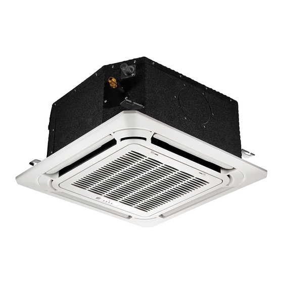
COMPACT CEILING CASSETTE
CAB/CYB Series
CAB: Cooling-Only Version
CYB: Cooling and Heating Version
®
Inverter+ and Inverter++ Models
9,000-18,000 BTU/hr
Installation
Manual
IMPORTANT NOTICE:
Please read this manual carefully before installing
or operating your new air conditioning system.
Be sure to save this manual for future reference.
®
Table of Contents

Related Manuals for Pioneer CYB Series


Summary of Contents for Pioneer CYB Series
-
Page 1: Installation Manual
DUCTLESS MINI SPLIT SYSTEM AIR CONDITIONER/HEAT PUMP COMPACT CEILING CASSETTE CAB/CYB Series CAB: Cooling-Only Version CYB: Cooling and Heating Version ® ® Inverter+ and Inverter++ Models 9,000-18,000 BTU/hr Installation Manual IMPORTANT NOTICE: Please read this manual carefully before installing or operating your new air conditioning system. - Page 2 • If used as a MULTI Unit, please refer to the Installation & Operation Manuals packed with the Outdoor Unit.
-
Page 3: Table Of Contents
CONTENTS Install strictly according to these installation instructions. If Page installation is done improperly, it can lead to water leakage, PRECAUTIONS ................... 1 electrical shock, and fire. INSTALLATION INFORMATION ............2 When installing the unit inside a small room, take measures to ACCESSORIES ................... -
Page 4: Installation Information
• There are inflammable materials or gas. If the refrigerant leaks during installation, ventilate the area immediately. • There is acid or alkaline liquid evaporating. Toxic gas may be produced if the refrigerant comes into contact with fire. • Other special conditions. The temperature of the refrigerant circuit will be high, so please The appliance shall be installed in accordance with national keep the interconnection cable away from the copper tube. -
Page 5: Accessories
ACCESSORIES Check if the following accessories are included with your un几 For the following items, take special care during Tick construction and check after installation is finished when checked Is the indoor unit fixed firmly? The unit may drop. vibrate, or make noise. P—什凸... -
Page 6: Indoor Unit Installation
INDOOR UNIT INSTALLATION Selecting t nstallation Site When the conditions in the ceiling exceed 30°C /86°F and a relative humidity of 80%, or when fresh air is inducted into the ceiling, an additional insulation layer is required (minimum 10 mm/ 0.4in thickness, polyethylene foam). -
Page 7: Preparations Before Installation
Make the ceiling opening needed for installation where Preparations Before Installation applicable. (For existing ceilings. ) Relation of ceiling opening to unit and suspension bolt - Create the ceiling opening required for installation. From the position. side of the opening to the casing outlet, implement the refrigerant and drain piping and wiring for remote controller (unnecessary for wireless type). - Page 8 Installin Indoor 4) Check that the unit is horizontally levelled. - Do not install the unit tilted. The indoor unit is equipped with a built-in drain pump and float switch. (If the unit is tilted against When installing optional accessories, read the installation manual the direction of the condensate flow (the drain piping side is of the optional accessories as well.
-
Page 9: Outdoor Unit Installation
Figure of OUTDOOR UNIT INSTALLATION Precautions for Location Selection 工 1) Choose a place sturdy enough to bear the weight and vibrations of the unit, and where the operation noise will not be amplified. 2) Choose a location where neither the hot air discharged from the unit nor the operation noise will cause a nuisance to the neighbors of the user. - Page 10 2.4 Outdoor nit Installation 2.3 Installation uidelines • When a wall, or other obstacle, is in the path of outdoor unit's 1) Installing Outdoor nit: inlet or outlet airflow, follow the installation guidelines below. • When installing the outdoor unit, refer to "Precautions for •...
-
Page 11: Installing The Refrigerant Pipe
INSTALLING THE REFRIGERANT PIPE Flaring the Pipe 1) Cut the pipe end with a pipe cutter. All field piping must be provided by a licensed refrigeration technician, and must comply with all relevant local and 2) Remove burrs with the cut surface, facing downward so that national codes. - Page 12 Air Evacuation BLUE (Low Pressure) Gauge RED (High Pressure) Gauge BLUE (Low Pressure) Side of Manifold Gauge RED (High Pressure) Side of Manifold Gauge Low Pressure Valve High Pressure Valve YELLOW (Common) Side of Manifold Gauge Caution: Systems are precharged with refrigerant (entire amount necessary for the system set has been charged into the outdoor section).
- Page 13 Copper Pipe from Indoor Unit Open the BLUE (Low Pressure) valve of Manifold Gauge. Keep the RED (High Pressure) valve closed. Flare Nut Turn the vacuum pump ON to start evacuating the air from the line set and indoor unit circuits. Run the vacuum pump for at least 15 minutes, or until the Low Pressure Gauge reads -76cmHG (-100 kPa or -30 In Hg).
-
Page 14: Connecting The Drain Pipe
CONNECT THE DRAIN PIPE 2) Be sure to insulate both the gas and liquid piping. Use separate thermal insulation pipes for gas and liquid refrigerant pipes. See the figure below. 4.1 Installation of Drain Piping Install the drain piping as shown in figure below, and take measures against condensation. -
Page 15: Electrical Wiring Work
. 4.4 Testing of Drain Piping 4.3 How to Perform Pipework After the piping work is finished, check if drainage flows smoothy Add approximately 1 L of water gradually through the air discharge outlet. Method of adding water (see the figure below): ·... - Page 16 Remove the control box lid of the indoor unit. . Remove the cover of the outdoor unit. How to onnect t Wiring Follow the "Wiring diagram label" attached to the indoor unit's control box lid to wire the outdoor unit, indoor unit, and the remote controller. ....
-
Page 17: Installation Of The Decoration Panel
. INSTALLATION OF THE DECORATION PANEL - After installing the decoration panel, ensure that there is no space between the unit body and decoration panel. Otherwise, Detach the intake grille. air may leak through the gap and cause dewdrops. Slide the 2 grille hooks toward the middle of the decoration (See figure below) panel. -
Page 18: Test Operation
. Close the intake grille, and slide the 2 grille hooks back. D[me]D TEST OPERATION Make sure the control box lids are closed on the indoor and outdoor units. Refer to "For the following items, take special care during construction and check after installation is finished"... - Page 19 is a registered trademark of Parker Davis HVAC International, Inc. Parker Davis HVAC International, Inc. 2250 NW 102 Place, Doral, FL 33172 - USA : (305) 513-4488 : (305) 513-4499 email : [email protected] Website: www.pd-hvac.com Copyright 2017, Parker Davis HVAC International, Inc., All rights reserved.