ABB ACS800 Hardware Manual
45 / 60 to 560 / 600 kw
Hide thumbs
Also See for ACS800:
- Firmware manual (340 pages) ,
- Hardware manual (210 pages) ,
- Cabinet installation and operating instruction (162 pages)
Table of Contents
Quick Links
ACS800
Hardware Manual
ACS800-02 Drives (45 to 560 kW)
ACS800-U2 Drives (60 to 600 HP)
Phone: 800.894.0412 - Fax: 888.723.4773 - Web: www.clrwtr.com - Email: [email protected]
Table of Contents

Related Manuals for ABB ACS800


Summary of Contents for ABB ACS800
- Page 1 ACS800 Hardware Manual ACS800-02 Drives (45 to 560 kW) ACS800-U2 Drives (60 to 600 HP) Phone: 800.894.0412 - Fax: 888.723.4773 - Web: www.clrwtr.com - Email: [email protected]...
-
Page 2: Acs800 Single Drive Manuals
ACS800 Single Drive Manuals HARDWARE MANUALS (appropriate manual is included in the delivery) ACS800-01/U1 Hardware Manual 0.55 to 160 kW (0.75 to 200 HP) 3AFE64382101 (English) ACS800-01/U1/04 Marine Supplement 0.55 to 160 kW (0.75 to 200 HP) 3AFE64291275 (English) ACS800-11/U11 Hardware Manual 5.5 to 110 kW (7.5 to 125 HP) 3AFE68367883 (English) ACS800-31/U31 Hardware Manual 5.5 to110 kW (7.5 to 125 HP) - Page 3 ACS800-02 Drives 45 to 560 kW ACS800-U2 Drives 60 to 600 HP Hardware Manual 3AFE64567373 Rev F EN EFFECTIVE: 15.8.2007 © 2007 ABB Oy. All Rights Reserved. Phone: 800.894.0412 - Fax: 888.723.4773 - Web: www.clrwtr.com - Email: [email protected]...
- Page 4 Phone: 800.894.0412 - Fax: 888.723.4773 - Web: www.clrwtr.com - Email: [email protected]...
-
Page 5: Safety Instructions
To which products this chapter applies This chapter applies to the ACS800-01/U1, ACS800-11/U11, ACS800-31/U31, ACS800-02/U2 and ACS800-04/04M/U4 of frame sizes R7 and R8. Use of warnings and notes There are two types of safety instructions throughout this manual: warnings and notes. -
Page 6: Installation And Maintenance Work
AGPS board (Prevention of Unexpected Start, ACS800-01/U1, ACS800-04/ 04M, ACS800-11/U11, ACS800-31/U31). • ACS800-02 with enclosure extension: The main switch on the cabinet door does not remove the voltage from the input busbars of the drive. Before working on the drive, isolate the whole drive from the supply. -
Page 7: Grounding
In addition, connect the cable shields to protective earth (PE) in order to meet safety regulations. ACS800-04 (45 to 560 kW) and ACS800-02 in first environment: make a 360° high frequency grounding of motor cable entries at the cabinet lead-through. -
Page 8: Mechanical Installation And Maintenance
Do not lift the unit by the front cover. Place the unit only on its back. ACS800-02, ACS800-04: The drive is heavy. Lift the drive by the lifting lugs only. Do not tilt the unit. The unit will overturn from a tilt of about 6 degrees. -
Page 9: Printed Circuit Boards
Printed circuit boards WARNING! Ignoring the following instructions can cause damage to the printed circuit boards: • The printed circuit boards contain components sensitive to electrostatic discharge. Wear a grounding wrist band when handling the boards. Do not touch the boards unnecessarily. Fibre optic cables WARNING! Ignoring the following instructions can cause equipment malfunction and damage to the fibre optic cables:... -
Page 10: Operation
Operation These warnings are intended for all who plan the operation of the drive or operate the drive. WARNING! Ignoring the following instructions can cause physical injury or death, or damage to the equipment: • Before adjusting the drive and putting it into service, make sure that the motor and all driven equipment are suitable for operation throughout the speed range provided by the drive. -
Page 11: Permanent Magnet Motor
Permanent magnet motor These are additional warnings concerning permanent magnet motor drives. Ignoring the instructions can cause physical injury or death, or damage to the equipment. Installation and maintenance work WARNING! Do not work on the drive when the permanent magnet motor is rotating. Also, when the supply power is switched off and the inverter is stopped, a rotating permanent magnet motor feeds power to the intermediate circuit of the drive and the supply connections become live. - Page 12 Safety instructions Phone: 800.894.0412 - Fax: 888.723.4773 - Web: www.clrwtr.com - Email: [email protected]...
-
Page 13: Table Of Contents
Providing feedback on ABB Drives manuals ........ - Page 14 ACS800-07/U7 units with line contactor (+F250) ........40...
- Page 15 To which products this chapter applies ..........89 Note for the ACS800-02 with enclosure extension and the ACS800-07 ..... 89 Table of contents Phone: 800.894.0412 - Fax: 888.723.4773 - Web: www.clrwtr.com - Email: [email protected]...
- Page 16 Note on terminal labelling ............89 Note on external power supply .
- Page 17 Technical data What this chapter contains ............109 IEC data .
- Page 18 To which products this chapter applies ..........145 Availability of brake choppers and resistors for the ACS800 ......145 How to select the correct drive/chopper/resistor combination .
-
Page 19: About This Manual
Planning the electrical installation, Motor control and I/O board (RMIO) Resistor braking, apply to several ACS800 products which are listed at the beginning of the chapters. Categorization according to the frame size Some instructions, technical data and dimensional drawings which concern only certain frame sizes are marked with the symbol of the frame size R2, R3... -
Page 20: Installation And Commissioning Flowchart
If the converter has been non-operational for equipment are present and correct. more than one year, the converter DC link capacitors need to be reformed. Ask ABB for Only intact units may be started up. instructions. Check the installation site. -
Page 21: Product And Service Inquiries
Address any inquiries about the product to your local ABB representative, quoting the type code and serial number of the unit in question. A listing of ABB sales, support and service contacts can be found by navigating to ABB website and selecting Drives –... - Page 22 About this manual Phone: 800.894.0412 - Fax: 888.723.4773 - Web: www.clrwtr.com - Email: [email protected]...
-
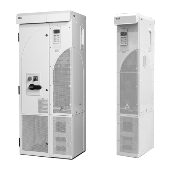
Page 23: The Acs800-02/U2
This chapter describes the construction and operating principle of the drive in short. The ACS800-02/U2 The ACS800-02 is a free-standing drive for controlling AC motors. In the basic unit, the cabling direction is from below. When an optional enclosure extension is connected next to the basic unit, the cables can also be led from above. -
Page 24: Enclosure Extension
Type code The type code contains information on the specifications and configuration of the drive. The first digits from left express the basic configuration (e.g. ACS800-02- 0170-5). The optional selections are given thereafter, separated by plus signs (e.g. +E202). The main selections are described below. Not all selections are available for all types. - Page 25 X2 (+C111 required) L505 thermistor relay (1 or 2 pcs, +C111 required) L506 Pt100 relay (3 pcs, +C111 required) L... Refer to ACS800 Ordering Information (EN code: 64556568). Fieldbus K... Refer to ACS800 Ordering Information (EN code: 64556568). Control program N...
-
Page 26: Main Circuit And Control
Type code selections for the ACS800-U2 Selection Alternatives Specialities P901 coated boards P904 extended warranty Main circuit and control Diagram This diagram shows the control interfaces and the main circuit of the drive. Motor Optional module 1: RMBA, RAIO, control and... -
Page 27: Operation
The motor control is based on the Direct Torque Control (DTC) method. Two phase currents and DC link voltage are measured and used for the control. The third phase current is measured for earth fault protection. The ACS800-02/U2 Phone: 800.894.0412 - Fax: 888.723.4773 - Web: www.clrwtr.com - Email: [email protected]... - Page 28 The ACS800-02/U2 Phone: 800.894.0412 - Fax: 888.723.4773 - Web: www.clrwtr.com - Email: [email protected]...
-
Page 29: Planning The Electrical Installation
Note: The installation must always be designed and made according to applicable local laws and regulations. ABB does not assume any liability whatsoever for any installation which breaches the local laws and/or other regulations. Furthermore, if the recommendations given by ABB are not followed, the drive may experience problems that the warranty does not cover. - Page 30 … then the motor voltage with … rating should be … diode supply no resistor braking is in use ACS800-01, -U1, -02, -U2, frequent or long term brake cycles will ACeq1 -04, -04M, -U4 -07, -U7 be used IGBT supply...
-
Page 31: Protecting The Motor Insulation And Bearings
The stress on motor insulation can be avoided by using optional ABB du/dt filters. du/dt filters also reduce bearing currents. -
Page 32: Requirements Table
Requirements table The following table shows how to select the motor insulation system and when an optional ABB du/dt filter, insulated N-end (non-drive end) motor bearings and ABB common mode filters are required. The motor manufacturer should be consulted regarding the construction of the motor insulation and additional requirements for explosion-safe (EX) motors. - Page 33 Motor type Nominal mains Requirement for voltage (AC line Motor insulation ABB du/dt filter, insulated N-end bearing and ABB common mode voltage) system filter < 100 kW 100 kW < P < 350 kW > 350 kW frame size > IEC 315 frame size <...
- Page 34 For motors with higher rated output than what is stated for the particular frame size in EN 50347 (2001) and for IP 23 motors, the requirements of ABB random-wound motor series M3AA, M3AP, M3BP are given below. For other motor types, see the Requirements table above.
-
Page 35: Permanent Magnet Synchronous Motor
Note 8: Calculating the rise time and the peak line-to-line voltage The peak line-to-line voltage at the motor terminals generated by the drive as well as the voltage rise time depend on the cable length. The requirements for the motor insulation system given in the table are “worst case”... -
Page 36: Supply Connection
AC power source and the drive. The disconnecting device must be of a type that can be locked to the open position for installation and maintenance work. ACS800-02 and ACS800-U2 with enclosure extension, ACS800-07 and ACS800-U7 These units are equipped with a hand-operated input disconnecting device (disconnecting means) which isolates the drive and the motor from the AC power as standard. -
Page 37: Thermal Overload And Short-Circuit Protection
Thermal overload and short-circuit protection Thermal overload protection of the drive and the input and motor cables The drive protects itself and the input and motor cables against thermal overload when the cables are dimensioned according to the nominal current of the drive. No additional thermal protection devices are needed. -
Page 38: Protection Against Short-Circuit Inside The Drive Or In The Supply Cable
Arrange the protection according to the following guide lines. Circuit diagram Drive type Short-circuit protection DRIVE IS NOT EQUIPPED WITH INPUT FUSES ACS800-01 Protect the drive and input cable with fuses Drive or drive Distribution ACS800-U1 or a circuit breaker. -
Page 39: Ground Fault Protection
2) Circuit breakers which have been tested by ABB with the ACS800 can be used. Fuses must be used with other circuit breakers. Contact your local ABB representative for the approved breaker types and supply network characteristics. The protective characteristics of circuit breakers depend on the type, construction and settings of the breakers. -
Page 40: Power-Loss Ride-Through Function
20.06 UNDERVOLTAGE CTRL is set to ON (default in Standard Control Program). ACS800-07/U7 units without line contactor The power-loss ride-through funtion is not in use. ACS800-07/U7 units with line contactor (+F250) The power-loss ride-through funtion is enabled by connecting RMIO board terminals X22:8 and X22:11 with a jumper. -
Page 41: Prevention Of Unexpected Start
(type BD5935 has been approved by ABB) For connections to the drive, see chapter Installation of AGPS board (Prevention of Unexpedted Start, +Q950) or the circuit diagram delivered with the drive (ACS800- 07/U7). WARNING! The Prevention of Unexpected Start function does not disconnect the voltage of the main and auxiliary circuits from the drive. -
Page 42: Selecting The Power Cables
Selecting the power cables General rules Dimension the mains (input power) and motor cables according to local regulations: • The cable must be able to carry the drive load current. See chapter Technical data for the rated currents. ° • The cable must be rated for at least 70 C maximum permissible temperature of conductor in continuous use. -
Page 43: Alternative Power Cable Types
Alternative power cable types Power cable types that can be used with the drive are represented below. Recommended Symmetrical shielded cable: three phase conductors A separate PE conductor is required if the conductivity and a concentric or otherwise symmetrically of the cable shield is < 50% of the conductivity of the constructed PE conductor, and a shield phase conductor. -
Page 44: Additional Us Requirements
Additional US requirements Type MC continuous corrugated aluminum armor cable with symmetrical grounds or shielded power cable must be used for the motor cables if metallic conduit is not used. For the North American market, 600 V AC cable is accepted for up to 500 V AC. -
Page 45: Equipment Connected To The Motor Cable
Stop the drive and wait for the motor to stop before opening a contactor between the output of the drive and the motor when the DTC control mode is selected. See the appropriate ACS800 control program firmware manual for the required parameter settings. Otherwise, the contactor will be damaged. In scalar control, the contactor can be opened with the drive running. -
Page 46: Protecting The Relay Output Contacts And Attenuating Disturbances In Case Of Inductive Loads
Protecting the relay output contacts and attenuating disturbances in case of inductive loads Inductive loads (relays, contactors, motors) cause voltage transients when switched off. The relay contacts on the RMIO board are protected with varistors (250 V) against overvoltage peaks. In spite of this, it is highly recommended to equip inductive loads with noise attenuating circuits [varistors, RC filters (AC) or diodes (DC)] in order to minimize the EMC emission at switch-off. -
Page 47: Selecting The Control Cables
Control panel cable In remote use, the cable connecting the control panel to the drive must not exceed 3 metres (10 ft). The cable type tested and approved by ABB is used in control panel option kits. Planning the electrical installation... -
Page 48: Connection Of A Motor Temperature Sensor To The Drive I/O
3. An external thermistor relay is used. The insulation of the relay must be rated for the same voltage level as the main circuit of the drive. For connection, see ACS800 Firmware Manual. Installation sites above 2000 metres (6562 feet) WARNING! Protect against direct contact when installing, operating and servicing the RMIO board wiring and optional modules attached to the board. -
Page 49: Control Cable Ducts
A diagram of the cable routing is shown below. Motor cable Drive min 300 mm (12 in.) Power cable Input power cable Motor cable 90 ° min 200 mm (8 in.) min 500 mm (20 in.) Control cables Control cable ducts 230 V 230 V (120 V) - Page 50 Planning the electrical installation Phone: 800.894.0412 - Fax: 888.723.4773 - Web: www.clrwtr.com - Email: [email protected]...
-
Page 51: What This Chapter Contains
Installation What this chapter contains This chapter describes the mechanical and electrical installation procedure of the drive. WARNING! Only qualified electricians are allowed to carry out the work described in this chapter. Follow the Safety instructions on the first pages of this manual. Ignoring the safety instructions can cause injury or death. - Page 52 WARNING! The drive is heavy [frame size R7: 110 kg (220 lb), frame size R8: 240 kg (507 lb)]. Lift the drive by the upper part only using the lifting lugs attached to the top of the unit. The lower part will be deformed from lifting. Do not remove the pedestal before lifting.
-
Page 53: Before Installation
Before installation Delivery check The drive is delivered in a box that also contains: • hardware manual • appropriate firmware manuals and guides • optional module manuals • delivery documents. Check that there are no signs of damage. Before attempting installation and operation, check the information on the type designation label of the drive to verify that the unit is of the correct type. -
Page 54: Requirements For The Installation Site
If a unit is mounted on the wall, the wall must be as close to vertical as possible, and strong enough to carry the weight of the unit. The drive must not be installed without the pedestal and a support shelf on wall, refer to ACS800-02/U2 Application Guide on Wall Mounting [3AFE68250013 (English)]. -
Page 55: It (Ungrounded) Systems
(ungrounded systems). If the drive is equipped with EMC filter +E202, disconnect the filter before connecting the drive to an ungrounded system. For detailed instructions on how to do this, please contact your local ABB representative. WARNING! If a drive with EMC filter +E202 is installed on an IT system [an... -
Page 56: Power Cable Connection Diagram
Power cable connection diagram Drive module OUTPUT INPUT UDC+ V1 W1 V2 W2 (PE) (PE) * For alternatives, see External brake Planning the electrical resistor installation: Disconnecting Motor device (disconnecting means) 1), 2) Grounding of the motor cable shield at the motor end If shielded cable is used (not required but For minimum radio frequency interference: recommended), use a separate PE cable (1) or a... -
Page 57: Installation Procedure
Installation procedure Choose the mounting orientation (a, b, c or d) Lifted from above With enclosure extension Symbols: required free space air inlet surface Note: The unit can also be installed away wall fixing point (recommended) from the wall. control panel mounting slot Frame Mounting Required free space around the unit for mounting, maintenance, service and cooling *... - Page 58 Use a torque wrench with an extension bar. 4. Wheel the drive frame out by using the handle. Wheeling the frame out 3 2 pcs ProE: ACS800-02-R7_manual2.drw Installation Phone: 800.894.0412 - Fax: 888.723.4773 - Web: www.clrwtr.com - Email: [email protected]...
- Page 59 Remove the pedestal (frame size R8): 1. Remove the lower front covers by undoing the fixing screws. 2. Press the left support leg a little down and turn it left. Let it lock down. Turn the right leg aside in the same way. The legs will prevent the unit from falling down during the installation.
- Page 60 Fix the lead-through plate to the floor: 1. Make a hole in the floor or cable conduit cover below the lead-through plate. See Dimensional drawings. 2. Check that the floor is horizontal with a spirit level. 3. Fasten the lead-through plate with screws or bolts. Note: The screws/bolts will be removed and refastened when the pedestal is fastened through the same holes later on.
- Page 61 Units with EMC screen (+E202) Remove the EMC screen by undoing the five fastening screws. Note: The screen must be replaced when the cables have been connected. Tightening torque of the fastening screws is 5 Nm (3.7 lbf ft). UDC+ UDC- Lead the power (input, motor and optional brake) cables through the lead-through plate: 1.
- Page 62 Prepare the power cables: 1. Strip the cables. 2. Twist the shield wires. 3. Bend the conductors to the terminals. 4. Cut the conductors to adequate length. Put the pedestal onto the lead-through plate and check the length of the conductors. Remove the pedestal. 5.
- Page 63 Frame size R8 64605569 Terminal hole 1 hole 2 hole 3 hole 1 hole 2 hole 3 Frame size R8 17.0 15.2 13.5 10.4 11.2 10.4 UDC- UDC+/R+ 10.4 PE busbar hole C / mm [in.] 24 [0.9] 56 [2.2] 88 [3.5] 120 [4.7] 152 [6.0] 184 [7.2] 216 [8.5] 248 [9.8] 280 [11.0] Lead the control cables through the lead-through plate: 1.
- Page 64 Connect the cable lugs to the pedestal: 1. If the lead-through plate is fixed to the floor, undo the fixing screws. 2. Place the pedestal onto the lead-through plate. 3. Fasten the pedestal and the lead-through plate to the floor with the screws through the same holes. 4.
-
Page 65: Mounting Orientation C (Lifting From Above)
• Fasten the lower front and side plates. • Fasten the drive by top to the wall (recommened). Note: When mounting the unit on wall, a support shelf is required, see the instructions in ACS800-02/U2 Application Guide on Wall Mounting [3AFE68250013 (English)]. Installation... -
Page 66: Mounting Orientation D (Optional Enclosure Extension Included)
Mounting orientation d (optional enclosure extension included) The customer connections of the drive (power cable terminals, I/O terminal blocks, option module slots) are provided in the enclosure extension instead of the actual drive cubicle. The extension cubicle and the drive cubicle are fastened together at the factory with two screws at the top of the cubicles. -
Page 67: Connecting The Power Cables
Connecting the power cables Refer to Dimensional drawings for terminal locations and hole sizes. The same screw can be used for connecting two cable lugs (on both sides of the busbar). Connecting the power cables of units without EMC filter +E202. Frame sizes R7 and R8. Step Instruction Lead the cables into the cubicle through the cable entries provided. - Page 68 Connecting the power cables of units with EMC filter +E202. Frame size R7 with bottom entry and exit. Step Instruction Photo Cut an adequate hole to the rubber grommet in the lead-through plate and lead the motor cable through the grommet and the conductive sleeve into the cabinet.
- Page 69 Connecting the power cables of units with EMC filter +E202. Frame size R7 with bottom entry and exit. Step Instruction Photo It is recommended to make a 360 degrees grounding for the input cable in the same way as for the motor cable.
- Page 70 Connecting the power cables of units with EMC filter +E202. Frame size R7 with top entry and exit. Step Instruction Photo Cut an adequate hole to the rubber grommet in the lead-through plate and lead the motor cable through the grommet and the conductive sleeve into the cabinet.
- Page 71 Connecting the power cables of units with EMC filter +E202. Frame size R7 with top entry and exit. Step Instruction Photo It is recommended to make a 360 degrees grounding for the input cable in the same way as for the motor cable.
- Page 72 Connecting the power cables of units with EMC filter +E202. Frame size R8 with bottom entry and exit. Step Instruction Photo Cut an adequate hole to the rubber grommet in the lead-through plate and lead the motor cable through the grommet and the conductive sleeve into the cabinet.
- Page 73 Connecting the power cables of units with EMC filter +E202. Frame size R8 with bottom entry and exit. Step Instruction Photo It is recommended to make a 360 degrees grounding for the input cable in the same way as for the motor cable.
- Page 74 Connecting the power cables of units with EMC filter +E202. Frame size R8 with top entry and exit. Step Instruction Photo Cut an adequate hole to the rubber grommet in the lead-through plate and lead the motor cable through the grommet and the conductive sleeve into the cabinet.
-
Page 75: Enclosure Extension Layout
Connecting the power cables of units with EMC filter +E202. Frame size R8 with top entry and exit. Step Instruction Photo It is recommended to make a 360 degrees grounding for the input cable in the same way as for the motor cable. - Page 76 Bottom cable entry/exit (R7) Installation Phone: 800.894.0412 - Fax: 888.723.4773 - Web: www.clrwtr.com - Email: [email protected]...
- Page 77 Top cable entry/exit (R7) Installation Phone: 800.894.0412 - Fax: 888.723.4773 - Web: www.clrwtr.com - Email: [email protected]...
- Page 78 Bottom cable entry/exit (R8) Installation Phone: 800.894.0412 - Fax: 888.723.4773 - Web: www.clrwtr.com - Email: [email protected]...
- Page 79 Top cable entry/exit (R8) Installation Phone: 800.894.0412 - Fax: 888.723.4773 - Web: www.clrwtr.com - Email: [email protected]...
-
Page 80: Main Wiring Diagram
Main wiring diagram The diagram below presents the main wiring of the enclosure extension. Note that the diagram includes optional components (marked *) which are not always included in the delivery. Installation Phone: 800.894.0412 - Fax: 888.723.4773 - Web: www.clrwtr.com - Email: [email protected]... -
Page 81: Routing The Control/Signal Cables Inside The Cubicle
Routing the control/signal cables inside the cubicle Units without an enclosure extension Frame size R7 Disconnect the control panel cables. Opening the top front cover (R7) Secure the cables with cable ties to the holes in the side bracket of the Frame size R8 capacitor pack. -
Page 82: Units With Enclosure Extension
Units with enclosure extension Cable entries with grommets for multiple cable diameters are provided. The following diagram gives an example of signal/control cabling routing inside the cubicle. RMIO Secure the cables with cable ties to these holes. Installation Phone: 800.894.0412 - Fax: 888.723.4773 - Web: www.clrwtr.com - Email: [email protected]... -
Page 83: Connecting The Control Cables
Connecting the control cables Connect the control cables as described below. Connect the conductors to the appropriate detachable terminals of the RMIO board (refer to chapter Motor control and I/O board (RMIO)). Tighten the screws to secure the connection. Connecting the shield wires at RMIO board Strain relief Strain relief Insulation... -
Page 84: Settings Of The Cooling Fan Transformer
Settings of the cooling fan transformer The voltage transformer of the cooling fan (T41) is located at the top of the drive module. Set to 220 V if the supply frequency is 60 Hz. (The voltage is set to 230 V (50 Hz) at the factory.) Set according to the supply voltage: 380 V, 400 V, 415 V, 440 V, 480 V or 500 V;... -
Page 85: Pulse Encoder Module Cabling
Pulse encoder module cabling Clamp as close to the terminals as possible. Alternative to a) Note1: If the encoder is of unisolated As short as type, ground the encoder cable at the possible drive end only. If the encoder is Strain relief galvanically isolated from the motor with a cable tie... -
Page 86: Fill-In User Connections Diagram
The following diagram is a fill-in template for the user’s power and control cable connections of units without enclosure extension. Factory Macro configurations of ACS800 Standard Control Program are shown. For other programs and macros, refer to the appropriate firmware manual. -
Page 87: Wiring Diagram Template
Wiring diagram template Installation Phone: 800.894.0412 - Fax: 888.723.4773 - Web: www.clrwtr.com - Email: [email protected]... - Page 88 Installation Phone: 800.894.0412 - Fax: 888.723.4773 - Web: www.clrwtr.com - Email: [email protected]...
-
Page 89: Motor Control And I/O Board (Rmio)
Motor control and I/O board (RMIO) What this chapter contains This chapter shows • external control connections to the RMIO board for the ACS800 Standard Control Program (Factory Macro) • specifications of the inputs and outputs of the board. To which products this chapter applies This chapter applies to ACS800 units which employ RMIO-01 board from revision J onwards and RMIO-02 board from revision H onwards. -
Page 90: Note On External Power Supply
Note on external power supply External +24 V power supply for the RMIO board is recommended if • the application requires a fast start after connecting the input power supply • fieldbus communication is required when the input power supply is disconnected. The RMIO board can be supplied from an external power source via terminal X23 or X34 or via both X23 and X34. -
Page 91: External Control Connections (Non-Us)
External control connections (non-US) External control cable connections to the RMIO board for the ACS800 Standard Control Program (Factory Macro) are shown below. For external control connections of other control macros and programs, see the appropriate Firmware Manual. RMIO RMIO VREF- Reference voltage -10 VDC, 1 kohm <... -
Page 92: External Control Connections (Us)
External control connections (US) External control cable connections to the RMIO board for the ACS800 Standard Control Program (Factory Macro US version) are shown below. For external control connections of other control macros and programs, see the appropriate Firmware Manual. -
Page 93: Rmio Board Specifications
RMIO board specifications Analogue inputs With Standard Control Program two programmable differential current inputs (0 mA / 4 mA ... 20 mA, R = 100 ohm) and one programmable differential voltage input (- 10 V / 0 V / 2 V ... +10 V, R = 200 kohm). -
Page 94: Relay Outputs
Maximum continuous current 2 A rms Insulation test voltage 4 kVAC, 1 minute DDCS fibre optic link With optional communication adapter module RDCO. Protocol: DDCS (ABB Distributed Drives Communication System) 24 VDC power input Voltage 24 VDC ± 10% Typical current consumption... - Page 95 Isolation and grounding diagram (Test voltage: 500 V AC) VREF- AGND VREF+ AGND AI1+ Common mode AI1- voltage between AI2+ channels ±15 V AI2- AI3+ AI3- AO1+ AO1- AO2+ AO2- Jumper J1 settings: DGND1 All digital inputs share a common ground.
- Page 96 Motor control and I/O board (RMIO) Phone: 800.894.0412 - Fax: 888.723.4773 - Web: www.clrwtr.com - Email: [email protected]...
-
Page 97: Installation Checklist
Installation checklist Checklist Check the mechanical and electrical installation of the drive before start-up. Go through the checklist below together with another person. Read the Safety instructions on the first pages of this manual before you work on the unit. Check MECHANICAL INSTALLATION The ambient operating conditions are allowed. - Page 98 Installation checklist Phone: 800.894.0412 - Fax: 888.723.4773 - Web: www.clrwtr.com - Email: [email protected]...
-
Page 99: Maintenance
Note: There are parts carrying dangerous voltages near the RMIO board when the drive is powered. Maintenance intervals If installed in an appropriate environment, the drive requires very little maintenance. This table lists the routine maintenance intervals recommended by ABB. Interval Maintenance Instruction... -
Page 100: Layout
Layout The layout stickers of the drive are shown below. The stickers show all possible components. Not all of them are present in each delivery or described here. Designation Component Control panel Motor control and I/O board (RMIO) Cooling fan Capacitors Code: 64572261-B Code: 64601423-B... -
Page 101: Heatsink
ABB. A cooling fan is included in the enclosure extension with a contactor option. Its lifespan is at least 40 000 h. Replacement fans are available from ABB. Do not use other than ABB specified spare parts. Maintenance... -
Page 102: Replacing The Fan(S) Of The Enclosure Extension
Replacing the fan(s) of the enclosure extension One or two fans are fastened to the inside of the roof. In addition, a fan is located at the side of the enclosure extension in the largest frame size R8 units for first environment (+E202): with bottom entry/exit at the left-hand side, with top entry/exit at the right-hand side. -
Page 103: Replacing The Fan (R7)
Replacing the fan (R7) 1. Remove the upper front cover and disconnect the control panel cables. 2. Disconnect the discharging resistor wire. 3. Remove the DC capacitor pack by undoing the red fixing screws and pulling the pack out. 4. Disconnect the fan supply wires (detachable connector). 5. -
Page 104: Replacing The Fan (R8)
Replacing the fan (R8) 1. Remove the front covers by undoing the fixing screws and disconnecting the control panel cable. 2. Disconnect the fan capacitor and power supply wires. 3. Remove the fan capacitor. 4. Units without enclosure extension: disconnect the power supply (a), fibre optic (b) and control panel (c) cables from the RMIO board. -
Page 105: Capacitors
It is not possible to predict a capacitor failure. Capacitor failure is usually followed by damage to the unit and an input cable fuse failure, or a fault trip. Contact ABB if capacitor failure is suspected. Replacements are available from ABB. Do not use other than ABB specified spare parts. -
Page 106: Replacing The Capacitor Pack (R8)
Replacing the capacitor pack (R8) 1. Remove the upper front covers and disconnect the control panel cable. Remove the side plate equipped with the control panel mounting slot. 2. Disconnect the discharging resistor wires. 3. Undo the fastening screws. 4. Lift the capacitor pack out. 5. -
Page 107: Module Replacement Of Units With The Enclosure Extension
Module replacement of units with the enclosure extension 1. Remove the upper front cover and disconnect the control panel cables. 2. Remove the lower front cover. 3. Undo the fastening screws of the pedestal. 4. Disconnect the pedestal from the drive module by undoing the connection screws. -
Page 108: Leds
LEDs This table describes LEDs of the drive. Where When the LED is lit RMIO board Drive in fault state Green The power supply on the board is OK. Control panel mounting platform Drive in fault state Green The main + 24 V power supply for the control panel and the RMIO board is OK. -
Page 109: Technical Data
CE and other markings, and warranty policy. IEC data Ratings The IEC ratings for the ACS800-02 with 50 Hz and 60 Hz supplies are given below. The symbols are described below the table. ACS800-02 Nominal ratings... - Page 110 ACS800-02 Nominal ratings Light-overload use Heavy-duty use Frame Air flow Heat overload size size dissipation cont.max cont.max Three-phase supply voltage 380 V, 400 V, 415 V, 440 V, 460 V, 480 V or 500 V -0170-5 3000 -0210-5 3800 -0260-5...
-
Page 111: Symbols
Symbols Nominal ratings continuous rms output current. No overload capability at 40 °C. cont.max maximum output current. Available for 10 s at start, otherwise as long as allowed by drive temperature. Typical ratings: No-overload use typical motor power. The power ratings apply to most IEC 34 motors at the nominal voltage, cont.max 230 V, 400 V, 500 V or 690 V. -
Page 112: Fuses
= transformer impedance (%) = transformer rated voltage (V) = nominal apparent power of the transformer (kVA) = cable reactance (ohm). Calculation example Drive: • ACS800-02-0260-3 • supply voltage U = 410 V Transformer: • rated power S = 3000 kVA •... -
Page 113: Fuse Tables
2 · The calculated short-circuit current 9.7 kA is higher than the minimum short-circuit current of the drive gG fuse type OFAF3H500 (8280 A). -> The 500 V gG fuse (ABB Control OFAF3H500) can be used. Fuse tables Ultrarapid (aR) fuses... -
Page 114: Gg Fuses
Ultrarapid (aR) fuses ACS800-02 Input current Min. short- Fuse size circuit current Manufacturer Type DIN 43620 Size Three-phase supply voltage 525 V, 550 V, 575 V, 600 V, 660 V or 690 V -0140-7 1520 68 500 Bussmann 170M3818 DIN1*... - Page 115 ACS800-02 Input current Min. short- Fuse size circuit current Manufacturer Type IEC size Three-phase supply voltage 380 V, 400 V, 415 V, 440 V, 460 V, 480 V or 500 V -0170-5 3820 550 000 ABB Control OFAF1H250...
-
Page 116: Quick Guide For Selecting Between Gg And Ar Fuses
The table below is a short cut in selecting between gG and aR fuses. The combinations (cable size, cable length, transformer size and fuse type) in the table fulfil the minimum requirements for the proper operation of the fuse. ACS800-02 size Cable type Supply transformer minimum apparent power S... -
Page 117: Cable Types
Selection of smaller fuses improves the protection, but may also affect the fuse life time and lead to unnecessary operation of the fuses. In case of any uncertainty regarding the drive protection, please contact your local ABB. Cable types The table below gives copper and aluminium cable types for different load currents. -
Page 118: Cable Entries
Cable entries Mains, motor and brake resistor cable terminal sizes (per phase), maximum accepted cable diameters and tightening torques are given below. The maximum allowed width of the cable lug is 38 mm. Frame U1, V1, W1, U2, V2, W2, UDC+/R+, UDC-, R- Earthing PE size Number of holes per... -
Page 119: Nema Data
NEMA data Ratings The NEMA ratings for the ACS800-U2 and ACS800-02 with 60 Hz supplies are given below. The symbols are described below the table. For sizing, derating and 50 Hz supplies, see data. ACS800-U2 size Normal use Heavy-duty use... -
Page 120: Symbols
30 °C (86 °F). If ambient temperature is 40 °C (104 °F), I is 704 A. higher value available if output frequency is above 41 Hz ACS800-U2 types only Symbols maximum output current. Available for 10 s at start, otherwise as long as allowed by drive temperature. -
Page 121: Ul Class T And L Fuses
UL class T and L fuses ACS800-U2 type Input Fuse current Manufacturer Type UL class Three-phase supply voltage 208 V, 220 V, 230 V or 240 V -0080-2 Bussmann JJS-250 -0100-2 Bussmann JJS-300 -0120-2 Bussmann JJS-400 -0140-2 Bussmann JJS-500 -0170-2... -
Page 122: Cable Types
Cable types Cable sizing is based on NEC Table 310-16 for copper wires, 75 °C (167 °F) wire insulation at 40 °C (104 °F) ambient temperature. Not more than three current-carrying conductors in raceway or cable or earth (directly buried). For other conditions, dimension the cables according to local safety regulations, appropriate input voltage and the load current of the drive. -
Page 123: Cable Entries
Cable entries Input, motor and brake resistor cable terminal sizes (per phase) and tightening torques are given below. For units without enclosure extension, one hole cable lugs (1/2 inch diameter) can be used. The maximum allowed width of the cable lug is 1.5 inches. -
Page 124: Input Power Connection
US and Canada: According to UL 508C (ACS800-U2 without enclosure extension) and protection (UL 508, UL 508A (ACS800-U2 with enclosure extension), the drive is suitable for use on a circuit CSA C22.2 No. 14-05) capable of delivering not more than 100 kA symmetrical amperes (rms) at 600 V maximum... -
Page 125: Cooling
Cooling Method Internal fan, flow direction from front to top Free space around the See chapter Installation. unit Cooling air flow IEC data. Degrees of protection IP 21 (UL type 1) Ambient conditions Environmental limits for the drive are given below. The drive is to be used in a heated, indoor, controlled environment. -
Page 126: Materials
For further information on environmental aspects and more detailed recycling instructions, please contact your local ABB distributor. Applicable standards The drive complies with the following standards. The compliance with the European Low Voltage Directive is verified according to standards EN 61800-5-1 and EN 60204-1. -
Page 127: Ce Marking
CE marking A CE mark is attached to the drive to verify that the unit follows the provisions of the European Low Voltage and EMC Directives (Directive 73/23/EEC, as amended by 93/68/EEC and Directive 89/336/ EEC, as amended by 2004/108EC). Definitions EMC stands for Electromagnetic Compatibility. -
Page 128: Second Environment (Drive Of Category C3)
Equipment 2. An EMC plan for preventing disturbances is drawn up for the installation. A template is available from the local ABB representative. 3. The motor and control cables are selected as specified in the Hardware Manual. 4. The drive is installed according to the instructions given in the Hardware Manual. -
Page 129: C-Tick" Marking
“C-tick” marking “C-tick” marking is required in Australia and New Zealand. A “C-tick” mark is attached to each drive in order to verify compliance with the relevant standard (IEC 61800-3 (2004) – Adjustable speed electrical power drive systems – Part 3: EMC product standard including specific test methods), mandated by the Trans-Tasman Electromagnetic Compatibility Scheme. -
Page 130: Second Environment (Drive Of Category C3)
Equipment 2. An EMC plan for preventing disturbances is drawn up for the installation. A template is available from the local ABB representative. 3. The drive is installed according to the instructions given in the Hardware Manual. 4. The motor and control cables used are selected as specified in the Hardware Manual. -
Page 131: Ul/Csa Markings
UL/CSA markings The ACS800-02 and ACS800-U2 are C-UL US listed and CSA marked. The approvals are valid with rated voltages (up to 600 V). The drive is suitable for use on a circuit capable of delivering not more than 100 kA rms symmetrical... - Page 132 Technical data Phone: 800.894.0412 - Fax: 888.723.4773 - Web: www.clrwtr.com - Email: [email protected]...
-
Page 133: Dimensional Drawings
Dimensional drawings The dimensions are given in milllimetres and [inches]. Dimensional drawings Phone: 800.894.0412 - Fax: 888.723.4773 - Web: www.clrwtr.com - Email: [email protected]... -
Page 134: Frame Size R7
Frame size R7 Dimensional drawings Phone: 800.894.0412 - Fax: 888.723.4773 - Web: www.clrwtr.com - Email: [email protected]... -
Page 135: Frame Size R8
Frame size R8 Dimensional drawings Phone: 800.894.0412 - Fax: 888.723.4773 - Web: www.clrwtr.com - Email: [email protected]... -
Page 136: Frame Size R7 With Enclosure Extension - Bottom Entry
Frame size R7 with enclosure extension – bottom entry Dimensional drawings Phone: 800.894.0412 - Fax: 888.723.4773 - Web: www.clrwtr.com - Email: [email protected]... - Page 137 Dimensional drawings Phone: 800.894.0412 - Fax: 888.723.4773 - Web: www.clrwtr.com - Email: [email protected]...
-
Page 138: Frame Size R7 With Enclosure Extension - Top Entry
Frame size R7 with enclosure extension – top entry Dimensional drawings Phone: 800.894.0412 - Fax: 888.723.4773 - Web: www.clrwtr.com - Email: [email protected]... - Page 139 Dimensional drawings Phone: 800.894.0412 - Fax: 888.723.4773 - Web: www.clrwtr.com - Email: [email protected]...
-
Page 140: Frame Size R8 With Enclosure Extension - Bottom Entry
Frame size R8 with enclosure extension – bottom entry Dimensional drawings Phone: 800.894.0412 - Fax: 888.723.4773 - Web: www.clrwtr.com - Email: [email protected]... - Page 141 Dimensional drawings Phone: 800.894.0412 - Fax: 888.723.4773 - Web: www.clrwtr.com - Email: [email protected]...
-
Page 142: Frame Size R8 With Enclosure Extension - Top Entry
Frame size R8 with enclosure extension – top entry Dimensional drawings Phone: 800.894.0412 - Fax: 888.723.4773 - Web: www.clrwtr.com - Email: [email protected]... - Page 143 Dimensional drawings Phone: 800.894.0412 - Fax: 888.723.4773 - Web: www.clrwtr.com - Email: [email protected]...
- Page 144 Dimensional drawings Phone: 800.894.0412 - Fax: 888.723.4773 - Web: www.clrwtr.com - Email: [email protected]...
-
Page 145: Resistor Braking
To which products this chapter applies This chapter applies to the ACS800-01/U1 (frame sizes R2 to R6), ACS800-02/U2 (frame sizes R7 and R8), ACS800-04/U4 (frame sizes R7 and R8) and ACS800-07/ U7 (frame sizes R6, R7 and R8). Availability of brake choppers and resistors for the ACS800 Frame R2 and R3 drives and 690 V units of frame size R4 have a built-in brake chopper as standard equipment. -
Page 146: Optional Brake Chopper And Resistor(S) For The Acs800-01/U1
Optional brake chopper and resistor(s) for the ACS800-01/U1 The nominal ratings for dimensioning the brake resistors for the ACS800-01 and ACS800-U1 are given below at an ambient temperature of 40 °C (104 °F). ACS800-01 type Braking power Brake resistor(s) - Page 147 ACS800-01 type Braking power Brake resistor(s) of the chopper ACS800-U1 type and the drive Type brcont Rcont (kW) (ohm) (kJ) (kW) 400 V units -0003-3 SACE08RE44 -0004-3 SACE08RE44 -0005-3 SACE08RE44 -0006-3 SACE08RE44 -0009-3 SACE08RE44 -0011-3 SACE15RE22 -0016-3 SACE15RE22 -0020-3 SACE15RE22...
- Page 148 ACS800-01 type Braking power Brake resistor(s) of the chopper ACS800-U1 type and the drive Type brcont Rcont (kW) (ohm) (kJ) (kW) 690 V units -0011-7 SACE08RE44 -0016-7 SACE08RE44 -0020-7 SACE08RE44 -0025-7 SACE08RE44 -0030-7 SACE15RE22 -0040-7 22/33 SACE15RE22 -0050-7 SACE15RE13 -0060-7...
-
Page 149: Acs800-07/U7
Optional brake chopper and resistor(s) for the ACS800-02/U2, ACS800-04/ 04M/U4 and ACS800-07/U7 The nominal ratings for dimensioning the brake resistors for the ACS800-02/U2, ACS800-04/04M/U4 and ACS800-07/U7 are given below at an ambient temperature of 40 °C (104 °F). ACS800 type... - Page 150 Continuous power (heat) dissipation of the resistor when placed correctly. Energy E dissipates in 400 seconds. Rcont ACS800-0x types only ACS800-Ux types only 240 kW possible if ambient temperature is below 33 °C (91 °F) 160 kW possible if ambient temperature is below 33 °C (91 °F) 630 kW possible if ambient temperature is below 33 °C (91 °F)
-
Page 151: Resistor Installation And Wiring
Combined braking cycles for R7: Examples max 5 s or 10 s or P br10 br30 brcont No braking max 30 s min. 30 s min. 30 s max 30 s min. 30 s • After P or P braking, the drive and the chopper will withstand P continuously. -
Page 152: Acs800-07/U7
Note: If an external brake chopper (outside the drive module) is used, a main contactor is always required. A thermal switch (standard in ABB resistors) is required for safety reasons. The cable must be shielded and not longer than the resistor cable. -
Page 153: Brake Circuit Commissioning
RMIO:X22 or X2: X22 +24VD +24VD Thermal switch DGND1 (standard in ABB re- Θ sistors) DGND2 DIIL For other control programs, the thermal switch may be wired to a different digital input. - Page 154 Resistor braking Phone: 800.894.0412 - Fax: 888.723.4773 - Web: www.clrwtr.com - Email: [email protected]...
-
Page 155: Non-Abb Du/Dt Filter Selection
Non-ABB du/dt filter selection What this chapter contains This chapter contains guidelines for selecting and installing a non-ABB du/dt filter with the drive. When a du/dt filter must be used A du/dt filter must be used with drives of voltages from 500 V to 690 V according to the Requirements table on page 32. - Page 156 6. The motor cable does not exceed the maximum length specified by the filter manufacturer and ACS800-02/U2 Hardware Manual. 7. Maximum output frequency does not exceed the limit specified by the filter manufacturer and 300 Hz specified by the drive.