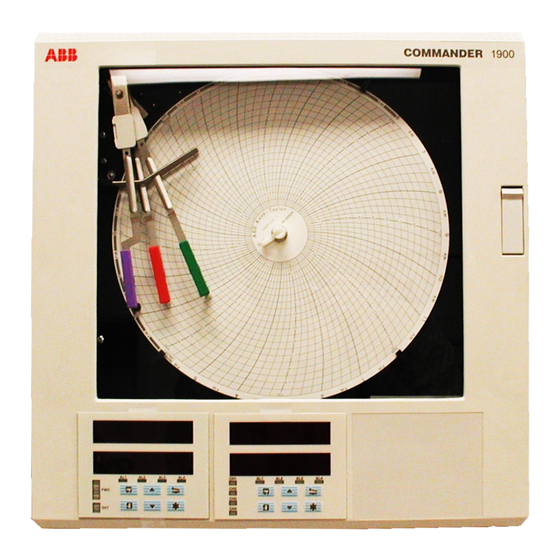
ABB COMMANDER 1900 Series User Manual
Circular chart recorders, advanced software options
Hide thumbs
Also See for COMMANDER 1900 Series:
- Programming manual (57 pages) ,
- Operating manual (44 pages) ,
- Installation manual (20 pages)

Related Manuals for ABB COMMANDER 1900 Series


Summary of Contents for ABB COMMANDER 1900 Series
- Page 1 User Guide COMMANDER 1900 Series Circular Chart Recorders Advanced Software Options...
- Page 2 St Neots, U.K. – Cert. No. Q5907 environmental applications. Stonehouse, U.K. – Cert. No. FM 21106 As a part of ABB, a world leader in process automation technology, we offer customers application expertise, service and support worldwide. EN 29001 (ISO 9001) We are committed to teamwork, high quality manufacturing, advanced technology and unrivalled service and support.
-
Page 3: Table Of Contents
CONTENTS 1 INTRODUCTION Section Page The C1900 Series of documentation is shown in Fig. 1.1. INTRODUCTION ............1 This supplement provides additional information for the • Ramp/Soak advanced software options, including: CONTROL CONFIGURATION LEVEL ....... 2 • Ramp/Soak Control Introduction to Ramp/Soak Profile Control ..3 •... -
Page 4: Ramp/Soak
• Ramp/Soak 2 CONTROL CONFIGURATION LEVEL OPrtOr LEVEL Operator Level bASIC Refer to Programming Guide Ramp/Soak Option CONFIG Basic Config CONtrL CONFIG Valve Page Set Up Control Page Set Up Operating Page Set Up Digital Ramp/Soak Profile Control Ramp/Soak Profile Program Set Points Page Control Config Section 2.2, Page 6... -
Page 5: Introduction To Ramp/Soak Profile Control
• Ramp/Soak 2 CONTROL CONFIGURATION LEVEL… 2.1 Introduction to Ramp/Soak Profile Control – Fig. 2.2 Information. • 10 programs per control channel. • Digital State program selection – allows digital inputs to select program to be run. • 99 programmable segments – can be shared between programs and controllers – see Fig. 2.3. •... -
Page 6: Program Configurations
• Ramp/Soak …2 CONTROL CONFIGURATION LEVEL 2.1.1 Program Configurations – Fig. 2.3 There are 99 segments that can be shared between programs and control channels. For normal applications it is recommended that segments 1 to 50 are assigned to channel 1 and segments 51 to 99 are assigned to channel 2. Fig. 2.3 shows 9 segments, shared between four separate programs on channel 1 and channel 2. -
Page 7: Self Seeking Set Point
• Ramp/Soak 2 CONTROL CONFIGURATION LEVEL… 2.1.3 Self-seeking Set Point – Fig. 2.5 The Self-seeking Set Point function reduces the delay between the end of a program and the beginning of the next program. The process variable value is used as the program start point and the set point steps up to the process variable value. This has the effect of changing the overall segment time and maintains a constant ramp rate. - Page 8 • Ramp/Soak …2 CONTROL CONFIGURATION LEVEL 2.2 Ramp/Soak Profile Control In this Section, parameters in the lower display denoted are Company Standard Settings. The instrument is dispatched programmed with these settings. PrOFLE Page Header – Profile Control. CONtrL To advance to the page press the switch.
-
Page 9: Ramp/Soak Profile Control
• Ramp/Soak 2 CONTROL CONFIGURATION LEVEL… …2.2 Ramp/Soak Profile Control rSt. S rc Program Reset Source Select the source required to reset a running program. The reset source is leading edge triggered. SEG 99 NONE If the program is running normally and is reset, the program returns to the beginning of the first segment and continues to run. - Page 10 • Ramp/Soak …2 CONTROL CONFIGURATION LEVEL 2.3 Ramp/Soak Profile Program PrOFLE Page Header – Profile Program. PrOGrM To advance to the frame press the switch. CONTROL CONFIGURATION LEVEL PrOGrM Select Program Ch1–1 Select the program to be configured: Program No. Ch1–1 Ch1–10 –...
-
Page 11: Ramp/Soak Profile Program
• Ramp/Soak 2 CONTROL CONFIGURATION LEVEL… …2.3 Ramp/Soak Profile Program SEGMNt rEPEAt Repeat Program Profile Set the number of times the program is to be repeated, between 0 and 99 or infinity. If infinity is selected the program is repeated until stopped by the operator. INFNtE HYSt Holdback Hysteresis... - Page 12 • Ramp/Soak …2 CONTROL CONFIGURATION LEVEL …2.3 Ramp/Soak Profile Program Source Description ACFAIL Power Failure SEG–99 Profile segment 99 SEG–0 Profile segment 0 PG-2. 1 0 Profile program 10, Controller 2 Profile (ramp/soak) control for controller 1 or 2 PG-1. 0 1 Profile program 1, Controller 1 ENd–x Program end (duration 1 second)
- Page 13 OPrtOr LEVEL Operator Level bASIC CONFIG Basic Config Refer to Programming Guide Totalization Option Maths Option Timer Option CONtrL CONFIG Control Config AdVNCd CONFIG Advanced Config Set Up Functions Set Up Logic Set Up Pen Function Input Assignment Set Up Totalizer Set Up Maths Set Up Timer Set Up Clock...
-
Page 14: Advanced Configuration Level
• Totalization 4 ADVANCED CONFIGURATION LEVEL 4.1 Introduction to Totalization Information. • One 8-digit totalizer per channel. • Count up or count down. • Count rates – from 0.001 to 100.0 counts/second. • External counter pulse – can be used to energize relays or digital outputs (a maximum of 4 pulses per second are generated). -
Page 15: Advanced Configuration Level
• Totalization 4 ADVANCED CONFIGURATION LEVEL… …4.1 Introduction to Totalization Example A – setting up: • engineering range of 0 to 2500 representing a range of 0 to 250,000 gallons per hour • filling a storage tank with a capacity of 500,000 gallons •... - Page 16 • Totalization …4 ADVANCED CONFIGURATION LEVEL 4.2 Set Up Totalizer In this Section, parameters in the lower display denoted are Company Standard Settings. The instrument is dispatched programmed with these settings. SEtUP Page Header – Set Up Flow Totals tOtALS To advance to the page press the switch.
-
Page 17: Set Up Totalizer
• Totalization 4 ADVANCED CONFIGURATION LEVEL… …4.2 Set Up Totalizer CUtOFF Cut-off Level Set the lowest value at which the totalizer is to stop counting (in engineering units). Example – On differential pressure flow, the inaccuracy of the system at very low flow rates may cause large accumulative totalizer errors due to erroneous counts. - Page 18 • Totalization …4 ADVANCED CONFIGURATION LEVEL …4.2 Set Up Totalizer Wrap On/Off If the wrap-around facility is selected, the front panel total is automatically reset to the Preset once the is reached. Value Predetermined Value If the wrap-around facility is not selected, the front panel total stops counting when the is reached.
-
Page 19: Introduction To Maths
• Maths 5 ADVANCED CONFIGURATION LEVEL 5.1 Introduction to Maths Information. • Four user-configurable maths blocks – can be used independently or cascaded together. • Each maths block can be configured to perform one of seven functions: Standard maths block (arithmetic operations) – add, subtract, divide, multiply, high select, low select and median Relative humidity (RH) –... -
Page 20: Relative Humidity (Rh)
• Maths …5 ADVANCED CONFIGURATION LEVEL 5.1.2 Relative Humidity (RH) The relative humidity calculation requires two inputs, one from a wet-bulb sensor and one from a dry-bulb sensor. Both of these inputs are configured as variables. RH tables are based on the use of an aspirated psychrometer having an air velocity of at least 11.5 feet per second or 3.5 meters per second across the bulb sensors. - Page 21 • Maths 5 ADVANCED CONFIGURATION LEVEL… …5.1.3 Mass Flow 1 and 2 Example A – calculating the mass flow of water from the volume flow. At a temperature of 60°F (520°R) and an absolute pressure of 14.696 p.s.i.a., 1 gallon (US) of water has a mass of 8.334 lbs. To calculate the mass flow of water from the volume flow the following settings are used: –...
- Page 22 • Maths …5 ADVANCED CONFIGURATION LEVEL …5.1.3 Mass Flow 1 and 2 Example B – calculating the mass flow of water from the volume flow. At a temperature of 15.6°C (288.6K) and an absolute pressure of 1013.25 mbar, 1 liter of water has a mass of 1kg. To calculate the mass flow of water from the volume flow the following settings are used: –...
-
Page 23: Maximum And Minimum Value
• Maths 5 ADVANCED CONFIGURATION LEVEL… 5.1.4 Maximum and Minimum Value – Fig. 5.1 If the High Value function is selected the maths result holds the value measured on an input variable. If the Low Value maximum function is selected the maths result holds the value measured on an input variable. -
Page 24: Set Up Maths
• Maths …5 ADVANCED CONFIGURATION LEVEL 5.2 Set Up Maths In this Section, parameters in the lower display denoted are Company Standard Settings. The instrument is dispatched programmed with these settings. SEt UP Page Header – Set Up Maths. MAtHS To advance to the page press the switch. - Page 25 • Maths 5 ADVANCED CONFIGURATION LEVEL… …5.2 Set Up Maths (Standard Maths Block) FUNCtN bLKx–1 Maths Block n /Element 1 (operand 1) CNSt–8 Select the source required for element 1. For description of operand sources for this and subsequent frames, refer to Table 5.1 on page 26. PV–1 bLKx.
- Page 26 • Maths …5 ADVANCED CONFIGURATION LEVEL …5.2 Set Up Maths (Relative Humidity) FUNCtN bULb–1 Wet-bulb Input CNSt–8 Select the process variable source required for wet-bulb input. For description of process variable sources, refer to Table 5.1 on page 26. PV–1 bULb–2 Dry-bulb Input CNSt–8...
- Page 27 • Maths 5 ADVANCED CONFIGURATION LEVEL… …5.2 Set Up Maths (Mass Flow) FUNCtN FUNCtN MASS–2 MASS–1 IPUt–A Mass Flow 1 or 2 Input Select the process variable source required for input A (input A is the input from volume flow or CNSt–8 differential pressure).
- Page 28 • Maths …5 ADVANCED CONFIGURATION LEVEL …5.2 Set Up Maths (Average) FUNCtN AVErGE INPUt Averaging Input CNSt–8 Select the input variable which is to be averaged. For description of the process variable sources, refer to below. Table 5.1 PV–1 tIME Time Scale Set the time scale interval over which the input is to be averaged, between 1 and 1440 minutes (24 hours).
-
Page 29: Maths Input Assignment
• Maths 5 ADVANCED CONFIGURATION LEVEL 5.3 Maths Input Assignment (for Controller versions refer to Programming Guide) Information. • To display or record a maths function – it must be assigned to a process variable or remote set point. • If the maths result is to be assigned to a process variable or remote set point – it is necessary to set up fault detection levels, broken sensor actions and an engineering range (high/low) in the Set Up Input Page, BASIC CONFIGURATION LEVEL. -
Page 30: Timer 6 Advanced Configuration Level
• Timer 6 ADVANCED CONFIGURATION LEVEL 6.1 Set Up Timer Information. • Two timers available. • ‘ON’ duration of 1 minute to 167 hours 59 minutes (1 week). • Programmable Timers – can operate on specific days, hours or minutes for an exact period of time. •... - Page 31 • Timer 6 ADVANCED CONFIGURATION LEVEL… …6.1 Set Up Timer Example B – setting up timer: • Monday enabled • Tuesday enabled • Wednesday enabled • Thursday enabled • Friday enabled • Saturday disabled • Sunday disabled • on hour set to 06.00am •...
-
Page 32: Timer. 2
• Timer …6 ADVANCED CONFIGURATION LEVEL …6.1 Set Up Timer SEt UP Page Header – Set Up Timer tIMEr To advance to the frame press the switch. SET UP CLOCK SELECt Select Timer tIMEr. 2 Select timer to be programmed: tIMEr–1 –... -
Page 33: Set Up Clock
• Timer 6 ADVANCED CONFIGURATION LEVEL 6.2 Set Up Clock Information. • Real time system clock included with timer option. • Provides date, month, day, hours, minutes. Page Header – Set Up Clock SEt UP To return to the top of the frame press the switch. - Page 34 NOTES...
- Page 35 PRODUCTS & CUSTOMER SUPPORT Products Customer Support Automation Systems ABB Automation provides a comprehensive after sales service • for the following industries: via a Worldwide Service Organization. Contact one of the – Chemical & Pharmaceutical following offices for details on your nearest Service and Repair –...
- Page 36 ABB Automation Inc. Howard Road, St. Neots 125 E. County Line Road Cambridgeshire, PE19 8EU Warminster, PA 18974 ABB Automation has Sales & Customer Support expertise in over 100 countries worldwide Tel: +44 (0)1480-475-321 Tel: +1 215-674-6000 Fax: +44 (0)1480-217-948 Fax: +1 215-674-7183 www.abb.com/automation...