Dell Edge 3000 Installation And Operation Manual
Hide thumbs
Also See for Edge 3000:
- Getting started manual (28 pages) ,
- Getting started manual (28 pages) ,
- Activation manual (9 pages)

Related Manuals for Dell Edge 3000


Summary of Contents for Dell Edge 3000
-
Page 1: Installation And Operation Manual
D D ell Edge Gateway 3000 Installation and Operation Manual Computer Model: Dell Edge Gateway 3000 Regulatory Model: N03G Regulatory Type: N03G001... - Page 2 WARNING: A WARNING indicates a potential for property damage, personal injury, or death. Copyright 2017 Dell Inc. or its subsidiaries. All rights reserved. Dell, EMC, and other trademarks are trademarks of Dell Inc. or its subsidiaries. Other trademarks may be trademarks of their respective owners.
-
Page 3: Table Of Contents
C C ontents 1 Overview......................... 5 2 System views........................6 ..................................... 6 Top view ..................................6 Bottom view .....................................7 Left view 3 Installing your Edge Gateway..................10 ............................. 10 Safety and regulatory information ..........................11 Professional installation instructions ........................11 Instructions d'installation professionnelles ..................11 Federal Communication Commission interference statement ............................ - Page 4 ............................65 Performance (BIOS level 1) ..........................65 Power management (BIOS level 1) .............................65 POST behavior (BIOS level 1) ........................... 66 Virtualization support (BIOS level 1) ............................66 Maintenance (BIOS level 1) ............................66 System logs (BIOS level 1) 9 Contacting Dell......................67...
-
Page 5: Overview
Overview The Edge Gateway 3000 Series is an Internet-of-Things (IoT) device. It is mounted at the edge of a network, enabling you to collect, secure, analyze, and act on data from multiple devices and sensors. It enables you to connect with devices used in transportation, building automation, manufacturing, and other applications. -
Page 6: System Views
System views Top view Table 1. Top view Features WLAN/Bluetooth/GPS connector Connect the antenna to increase the range and strength of wireless/bluetooth/satellite signals. Mobile broadband antenna-connector one (3G/ Connect the mobile broadband antenna to increase the range and LTE) strength of mobile broadband signals. ZigBee antenna connector Connect the ZigBee antenna for intermittent data transmissions from a ZigBee-compliant sensor or input device. -
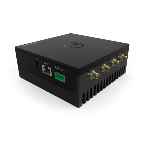
Page 7: Left View
Features Service Tag label The Service Tag is a unique alphanumeric identifier that enables the Dell service technicians to identify the hardware components in your Edge Gateway and access warranty information. Earth ground A large conductor attached to one side of the power supply, which serves as the common return path for current from many different components in the circuit. - Page 8 F F eatures USB 3.0 port Connect a USB enabled device. Provides data transfer speeds up to 5 Gbps. SIM card slot (optional) Insert a micro-SIM card into the slot. SD card slot (optional) Insert a micro-SD card into the slot. NOTE: Remove the SD card slot filler before inserting the micro-SD card.
- Page 9 F F unction Indicator Color Control Status related to packet density. NOTE: The power/system status light may operate differently during different boot-up scenarios. For example, when a USB script file is run during boot-up. Table 5. Power connector pin definition details Signal Function 12–57 VDC power...
-
Page 10: Installing Your Edge Gateway
WARNING: Before you begin any of the procedures in this section, read the safety and regulatory information that is shipped with your system. For additional best practices information, go to www.dell.com/regulatory_compliance. Safety and regulatory information WARNING: The Edge Gateway must be installed by knowledgeable, skilled persons familiar with local and/or international electrical codes and regulations. -
Page 11: Professional Installation Instructions
W W ARNING: The core module only can be wall-mounted (without the need for an additional enclosure). Professional installation instructions Installation personnel This product is designed for specific applications and needs to be installed by qualified personnel with RF and regulatory-related knowledge. -
Page 12: Industry Canada Statement
This equipment has been tested and found to comply with the limits for a Class A digital device, pursuant to Part 15 of the FCC Rules. These limits are designed to provide reasonable protection against harmful interference in a residential installation. This equipment generates, uses, and can radiate radio frequency energy and, if not installed and used in accordance with the instructions, may cause harmful interference to radio communications. -
Page 13: Setting Up Your Edge Gateway
Cet appareil et son antenne ne doivent pas être situés ou fonctionner en conjonction avec une autre antenne ou un autre émetteur, exception faites des radios intégrées qui ont été testées. The County Code Selection feature is disabled for products marketed in the US/Canada. La fonction de sélection de l'indicatif du pays est désactivée pour les produits commercialisés aux États-Unis et au Canada. - Page 14 3000 Not applicable Not applicable N N OTE: Use only the supplied antennas or third-party antennas that meet the minimum specifications. NOTE: Depending on the configuration ordered, some of the antenna connectors may not be present or may be capped. NOTE: Mobile broadband antenna connector two is for LTE Auxiliary only, it does not support 3G.
- Page 15 5 5 . Connect all desired cables to the appropriate I/O ports on the Edge Gateway. Open the micro-SIM/micro-SD card access door. Insert a micro-SIM card into the top micro-SIM card slot and activate your mobile broadband service.
- Page 16 C C AUTION: Dell recommends that you insert the micro-SIM card before turning on the Edge Gateway. NOTE: Ensure that you firmly screw back the access door after closing. NOTE: Contact your service provider to activate your micro-SIM card. Insert a micro-SD card into the bottom micro-SD card slot.
- Page 17 N N OTE: Secondary enclosures are sold separately. 10. Connect the Edge Gateway to one of the following power sources: • DC-IN •...
- Page 18 Accessing Dell Command | Configure on Ubuntu Core 16 On the systems running Ubuntu Core 16, Dell Command | Configure can be accessed from any location using the command NOTE: For more information about using the Dell Command | Configure application, see the Dell Command | Configure Installation Guide and User's Guide at www.dell.com/dellclientcommandsuitemanuals.
-
Page 19: Activating Your Mobile Broadband Service
• VESA mount A A ctivating your mobile broadband service CAUTION: Before turning on the Edge Gateway, insert the micro-SIM card. NOTE: Ensure that the service provider has already activated the micro-SIM card before using it in the Edge Gateway. Remove the screw to open the micro-SIM card access door. -
Page 20: Mounting Your Edge Gateway
Example (AT&T): Example (3G): Connect to the mobile network: Command line: Example (Verizon): Example (AT&T): Example (3G): To disconnect from the mobile network: Command line: Example (Verizon): Example (AT&T): Example (3G): M M ounting your Edge Gateway NOTE: Mounting can be completed before or after configuring your Edge Gateway. NOTE: Mounting options are sold separately. - Page 21 N N OTE: The mounting brackets are shipped with only those screws that are required for securing the mounting brackets to the Edge Gateway. Secure the standard-mount bracket to the back of the Edge Gateway by using the four M4x4.5 screws. NOTE: Torque the screws at 8 ±...
- Page 22 2 2 . Place the Edge Gateway against the wall, and align the holes in the standard-mount bracket with the holes on the wall. Screw holes on the bracket have a diameter of 3 mm (0.12 in).
- Page 23 3 3 . Place the standard-mount bracket on the wall, and using the holes above the screw holes on the bracket, mark the positions to drill the four holes.
- Page 24 4 4 . Drill four holes in the wall as marked. Insert and tighten four screws (not supplied) to the wall. Purchase screws that fit the diameter of the screw holes.
- Page 25 6 6 . Align the screw holes on the standard-mount bracket with the screws on the wall, letting the assembly hang on the screws.
- Page 26 7 7 . Tighten the screws to secure the assembly to the wall.
-
Page 27: Mounting The Edge Gateway On A Din Rail Using The Din-Rail Bracket
M M ounting the Edge Gateway on a DIN rail using the DIN-rail bracket NOTE: The DIN-rail bracket includes the screws that are required for securing the bracket to the Edge Gateway. Align the screw holes on the DIN-rail bracket with the screw holes at back of the Edge Gateway. Place the two M4x7 screws on the DIN-rail bracket and secure it to the Edge Gateway. - Page 28 3 3 . Secure the DIN-rail mounting bracket to the Edge Gateway by using the two M4x7 screws provided. NOTE: Torque the screws at 8±0.5 kilograms-centimeter (17.64±1.1 pounds-inch) on the DIN-rail mounting bracket.
- Page 29 4 4 . Place the Edge Gateway on the DIN rail at an angle, and then pull the Edge Gateway down to compress the springs at the top of the DIN-rail mounting bracket. Push the Edge Gateway towards the DIN-rail bracket to secure the lower clip of the bracket onto the DIN rail.
-
Page 30: Mounting The Edge Gateway Using The Quick-Mount Bracket
N N OTE: For more information about demounting the DIN-rail, see Demounting DIN rail. Mounting the Edge Gateway using the quick-mount bracket The quick-mount bracket is a combination of the standard-mount bracket and the DIN-rail bracket. NOTE: The mounting brackets are shipped with only those screws that are required for securing the mounting brackets to the Edge Gateway. - Page 31 2 2 . Drill four holes in the wall as marked. Insert and tighten four screws (not supplied) to the wall. Purchase screws that fit the diameter of the screw holes.
- Page 32 4 4 . Align the screw holes on the standard-mount bracket with the screws on the wall, letting the bracket hang on the screws.
- Page 33 5 5 . Tighten the screws to secure the assembly to the wall.
- Page 34 6 6 . Align the screw holes on the DIN-rail bracket with the screw holes at the back of the Edge Gateway. Place the two M4x7 screws on the DIN-rail bracket and secure it to the Edge Gateway.
- Page 35 8 8 . Place the Edge Gateway on the standard mount at an angle, and then pull the Edge Gateway down to compress the springs at the top of the DIN-rail bracket.
- Page 36 9 9 . Push the Edge Gateway towards the DIN-rail brackets to secure it on the standard-mount bracket.
-
Page 37: Mounting The Edge Gateway Using The Perpendicular Mount
N N OTE: For more information about demounting the DIN-rail, see Demounting DIN rail. Mounting the Edge Gateway using the perpendicular mount NOTE: The perpendicular mount is designed for DIN-rail applications only. Align the screw holes on the perpendicular-mount bracket with the screw holes on the Edge Gateway. - Page 38 2 2 . Tighten the four M4x7 screws to secure the Edge Gateway to the perpendicular-mount bracket. NOTE: Torque the screws at 8±0.5 kilograms-centimeter (17.64±1.1 pounds-inch).
- Page 39 3 3 . Align the screw holes on the DIN-rail mount bracket with the screw holes on the perpendicular-mount bracket, and tighten the two screws. NOTE: Torque the screws at 8±0.5 kilograms-centimeter (17.64±1.1 pounds-inch).
- Page 40 4 4 . Place the Edge Gateway on the DIN rail at an angle and push the Edge Gateway down to compress the springs on the DIN-rail mount brackets. Push the Edge Gateway towards the DIN-rail brackets to secure the bottom of the bracket to the DIN rail.
- Page 41 6 6 . Push the Edge Gateway towards the DIN-rail brackets to secure the lower clip of the bracket onto the DIN rail. Secure the Edge Gateway on the DIN rail.
-
Page 42: Attaching The Cable Control Bars To The Standard-Mount Bracket
A A ttaching the cable control bars to the standard-mount bracket Mount the Edge Gateway on the wall using the standard-mount bracket quick-mount bracket. Place the cable control bar on the mounting bracket and secure it to the notch. CAUTION: Use the top cable control bar only with coaxial cable connections. Do not use with antennas. - Page 43 3 3 . Align the screw holes on the cable control bar with the screw holes on the mounting bracket. Tighten the six M3 x 3.5 mm screws that secure the cable control bar to the mounting bracket. NOTE: Torque the screws at 5±0.5 kilograms-centimeter (11.02±1.1 pounds-inch).
- Page 44 5 5 . Connect the cables to the Edge Gateway. Loop the cable lock (not supplied) to secure each cable to the cable control bar.
-
Page 45: Mounting The Edge Gateway Using A Vesa Mount
M M ounting the Edge Gateway using a VESA mount The Edge Gateway can be mounted on a standard VESA mount (75 mm x 75 mm). NOTE: The VESA mount option is sold separately. For VESA mounting instructions, see the documentation that is shipped with the VESA mount. -
Page 47: Setting Up The Zigbee Dongle
Setting up the ZigBee dongle CAUTION: Do not connect the ZigBee dongle if the Edge Gateway is installed inside the enclosure. Turn off your Edge Gateway. Connect the ZigBee dongle to any external USB port on your Edge Gateway. Turn on your Edge Gateway, and complete the setup. NOTE: For more information about the ZigBee development, see www.silabs.com. -
Page 48: Setting Up The Operating System
Setting up the operating system WARNING: To prevent operating system corruption from sudden power loss, use the operating system to gracefully shut down the Edge Gateway. The Edge Gateway is shipped with one of the following operating systems: • Windows 10 IoT Enterprise LTSB 2016 •... -
Page 49: Restoring Windows 10 Iot Enterprise Ltsb 2016
.NET Framework 4.5.2 or higher • A working computer with administrator user rights and at least 8 GB of available data storage to download the Dell ISO recovery image. Double-click the Dell OS Recovery Tool icon from your desktop. Click Yes in the User Account Control prompt. - Page 50 C C loud LED NOTE: To utilize the Cloud LED, download the necessary tools and drivers from www.dell.com/support. One unique feature of the Edge Gateway 3000 Series is the Cloud LED. Cloud LED enables you to visually inspect the operational status of the Edge Gateway by looking at the display light on the left panel of the Edge Gateway.
-
Page 51: Ubuntu Core 16
U U buntu Core 16 Overview Ubuntu Core 16 is a Linux OS distribution that is an entirely new mechanism for managing a system and its applications. For more information about Ubuntu Core 16 OS, see • www.ubuntu.com/cloud/snappy • www.ubuntu.com/internet-of-things Prerequisites Infrastructure An active connection to the internet is needed to update the Ubuntu Core 16 operating system as well as applications (snaps). -
Page 52: Useful Commands
N N OTE: Check if a newer version of the software is available. For more information on checking for updates, see Updating operating system and applications. Useful commands To access the built-in help, run the command. To see a list of all the snaps that are currently installed, run the command. - Page 53 Check if the update is available from LVFS service. Download the firmware. Apply the update. Check EFI boot details. Restart the system. System Service Tag identity Run the following command: The system tag is printed. Dell/OEM system identity Run the following commands: Returns:...
-
Page 54: Network Communication Interfaces
S S ystem PowerOff Run the following command: The system shuts down successfully. Network communication interfaces The Edge Gateway 3000 series comes with one Ethernet connection, one 802.11b/g/n wireless network connection, and one Bluetooth network connection. Ethernet (Port 1, eth0) Assuming that you have an internet-enabled Ethernet cable plugged into Port1, your screen should be similar to the one below after running the command. - Page 55 • Disconnect Enter the following at the command prompt to add a connection to the system. For example: Enter the following at the command prompt to provide the system what passkey is used on the access point. For example: Enter the following at the command prompt to provide the system what is the pass code for the access point. For example: Enter the following at the command prompt to bring up the connection (allows it to connect to the access point and get an IP address).
-
Page 56: Security
You can start using the bluetooth keyboard. S S oftware enabled Access Point (SoftAP) The Software enabled Access Point (SoftAP) feature depends on the WiFi card and associated driver support to act as a wireless access point. Run the following commands: Check the access point status. -
Page 57: Restoring Ubuntu Core 16
• Ubuntu Desktop ISO NOTE: You can download the latest version of the Ubuntu ISO file from http://releases.ubuntu.com. • A released Ubuntu Core 16 image from Dell/Canonical:img.xz • Dell Edge Gateway 3000 series hardware • USB keyboard •... -
Page 58: 6 Bios And Uefi
On Ubuntu Core 16: On the connected computer running Ubuntu Core, access Dell Command | Configure using the command For more information on how to use the Dell Command | Configure application, see the Dell Command | Configure Installation Guide and User's Guide at www.dell.com/dellclientcommandsuitemanuals. -
Page 59: Ubuntu Core 16
D D ell Command | Configure (DCC) Use DCC to update and configure the BIOS settings. For more information on how to use the Dell Command | Configure application, see the Dell Command | Configure Installation Guide and User's Guide at www.dell.com/dellclientcommandsuitemanuals. -
Page 60: References
Dell Command | Configure Reference Guide • Dell Command | Monitor User's Guide • Dell Command | PowerShell Provider User's Guide For more information on using Dell Data Protection | Encryption see the documentation for the software at www.dell.com/ support/manuals. -
Page 61: Appendix
NOTE: Use only the supplied or an approved replacement antenna. NOTE: Modifications to the device and/or use of unauthorized antennas not expressly approved by Dell is the sole responsibility of the user or configurator or operator to reassess the equipment in accordance to all applicable international Safety, EMC, and RF standards. -
Page 62: De-Mounting From Din-Rail Bracket
T T able 8. Mobile broadband auxiliary antenna maximum gain (dBi) Antenna position—Bent Antenna position—Straight Frequency (MHz) 4G (dBi) 4G (dBi) 704~806 824~894 –0.3 –0.1 880~960 –1.9 –2.5 1710~1880 1850~1990 1920~2170 Table 9. WiFi/GPS antenna maximum gain (dBi) Antenna position—Bent Antenna position—Straight Frequency (MHz) GPS (dBi) -
Page 63: Default Bios Settings
D D efault BIOS settings System configuration (BIOS level 1) BIOS level 2 BIOS level 3 Item Default value Integrated NIC Integrated NIC Enable UEFI Network Stack Enabled [Enable/Disable] [Disabled, Enabled, Enabled w/ Enabled w/PXE PXE] USB Configuration USB Configuration Enable Boot Support [Enable/ Enabled Disable]... - Page 64 B B IOS level 2 BIOS level 3 Item Default value System Password System Password Enter the old password Not Set Enter the new password Not applicable Confirm new password Not applicable Strong Password Strong Password Enable Strong Password Disabled [Enable/Disable] Password Configuration Password Configuration...
-
Page 65: Secure Boot (Bios Level 1)
S S ecure boot (BIOS level 1) BIOS level 2 BIOS level 3 Item Default value Secure Boot Enable Secure Boot Enable [Enable/Disable] Disabled Expert Key Management Expert Key Management Enable Custom Mode [Enable/ Disabled Disable] Custom Mode Key Management {PK/KEK/db/ dbx} Performance (BIOS level 1) BIOS level 2... -
Page 66: Virtualization Support (Bios Level 1)
B B IOS level 2 BIOS level 3 Item Default value Fastboot Fastboot [Minimal/Thorough/Auto] Thorough Extend BIOS POST Time Extend BIOS POST Time [0 seconds/5 seconds/10 0 seconds seconds] Full Screen Logo Enable Full Screen Logo Disabled [Enable/Disable] Warnings and Errors Warnings and Errors [Prompt on Warnings and Prompt on Warnings and Errors... -
Page 67: Contacting Dell
Go to www.dell.com/contactdell. Verify your country or region in the drop-down list at the bottom of the page. Select the appropriate service or support link based on your requirement or choose the method of contacting Dell that is convenient for you.