Hitachi AMS 2100 Hardware Manual
Hide thumbs
Also See for AMS 2100:
- Getting started manual (54 pages) ,
- User manual (210 pages) ,
- Service manual (192 pages)

Related Manuals for Hitachi AMS 2100


Summary of Contents for Hitachi AMS 2100
- Page 1 Hitachi AMS 2100/2300 Storage System Hardware Guide INKS Document conventions Product version Getting help Table of Contents MK-97DF8010EN-26...
- Page 2 (hereinafter referred to as “Hitachi”). Hitachi, Ltd. and Hitachi Data Systems reserve the right to make changes to this document at any time without notice and assume no responsibility for its use. Hitachi, Ltd. and Hitachi Data Systems products and services can only be ordered under the terms and conditions of Hitachi Data Systems' applicable agreements.
-
Page 3: Table Of Contents
AMS 2100 base unit ........ - Page 4 Architecture and components ....... . . 2-2 AMS 2100 configuration architecture ......2-2 AMS 2300 configuration architecture .
- Page 5 AMS 2300 Rev2 Fibre channel control unit RKEM ....4-17 AMS 2100/2300 iSCSI control unit ......4-19 Fibre channel host connectors.
- Page 6 Installing an AMS 2100/2300 ........5-24...
- Page 7 Communication modes ........7-7 Configuring an AMS 2100/2300........7-8 Prerequisites .
- Page 8 Uninstalling Navigator 2 ........7-57 viii Table of Contents Hitachi AMS 2100/2300 Storage System Hardware Guide...
- Page 9 Incorrect installation ........11-2 Table of Contents Hitachi AMS 2100/2300 Storage System Hardware Guide...
- Page 10 Recycling ..........B-5 Glossary Index Table of Contents Hitachi AMS 2100/2300 Storage System Hardware Guide...
-
Page 11: Preface
Preface Congratulations on purchasing a new Hitachi AMS 2100/2300 Storage System. This guide will assist you in installing, configuring, and maintaining your Hitachi AMS 2100/2300. This preface includes the following information: Intended audience Product version Release notes and readme ... -
Page 12: Intended Audience
Chapter/Appendix Description Title Chapter 1, Introduction This chapter provides a brief overview of the AMS 2100/ 2300. Chapter 2, Functional This chapter describes the basic features of the AMS 2100/ and operational 2300 models. -
Page 13: Document Conventions
AMS 2100/2300. Appendix A, This appendix provides the mechanical, electrical, Specifications environmental, and other specifications for the AMS 2100/ 2300 systems. Complete specifications are contained in the Hitachi AMS 2000 Family Storage System Reference Guide. Appendix B, Regulatory... -
Page 14: Convention For Storage Capacity Values
1,024 KB or 1024 bytes 1 GB 1,024 MB or 1024 bytes 1 TB 1,024 GB or 1024 bytes 1 PB 1,024 TB or 1024 bytes 1 EB 1,024 PB or 1024 bytes Preface Hitachi AMS 2100/2300 Storage System Hardware Guide... -
Page 15: Accessing Product Documentation
Accessing product documentation The AMS 2000 Family user documentation is available on the Hitachi Data Systems Portal: https://portal.hds.com. Please check this site for the most current documentation, including important updates that may have been made after the release of the product. - Page 16 AMS 2000 Family ShadowImage In-system Replication User Guide, MK-97DF8129 Describes how to perform high-speed nondisruptive local mirroring to create a copy of mission-critical data in AMS 2100, AMS 2300, and AMS 2500 storage systems. ShadowImage keeps data RAID-protected and fully recoverable, without affecting service or performance levels.
- Page 17 AMS 2000 Family storage system. They also provide a wide range of technical information and specifications for the AMS 2000 Family storage systems. The symbol identifies documents that contain initial configuration information about Hitachi AMS 2000 Family storage systems. AMS 2100/2300 Storage System Hardware Guide, MK-97DF8010 — this document Provides detailed information about installing, configuring, and maintaining an AMS 2100/2300 storage system.
- Page 18 AMS 2000 Family Command Control Interface (CCI) Reference Guide, MK-97DF8121 Contains reference, troubleshooting, and maintenance information related to CCI operations on AMS 2100, AMS 2300, and AMS 2500 storage systems. AMS 2000 Family Command Control Interface (CCI) User’s Guide, MK-97DF8123 Describes how to use CCI to perform TrueCopy and ShadowImage operations on AMS 2100, AMS 2300, and AMS 2500 storage systems.
-
Page 19: Getting Help
Hitachi Dynamic Replicator - Scout Quick Install/Upgrade Guide, MK-98DF8222 Getting help If you need to contact the Hitachi Data Systems support center, please provide as much information about the problem as possible, including: • The circumstances surrounding the error or failure. - Page 20 Preface Hitachi AMS 2100/2300 Storage System Hardware Guide...
-
Page 21: Introduction
Introduction This chapter provides an overview of the Hitachi AMS 2100/2300 Storage System. It covers the following key topics: Array overview Features and benefits High capacity cache Performance reporting and monitoring Reliability, availability, and serviceability ... -
Page 22: Array Overview
AMS 2300 (Hitachi factory designation RKM) • Optional expansion units. For the AMS 2100, one to seven expansion units, and for the AMS 2300, one to 15 expansion units. An expansion unit provides additional storage space and can connect the base unit to additional expansion units or high-density expansion units. -
Page 23: Control Unit Configurations
Control unit configurations The Hitachi Data Systems AMS 2100/2300 base units support the following controller configurations. Numbers are total per base unit. Table 1-1: AMS 2100/2300 Control Unit Configurations... -
Page 24: Power Switch
They are all described briefly in this chapter and in detail in Chapter 4, Hardware components. The front of the AMS 2100 and AMS 2300 base units are identical. Light- Emitting Diode (LED) indicators show the unit’s power, ready, warning, and alarm status. Power switch The Power switch for turning the controllers and drives in a base unit is also located on the front of the unit. - Page 25 When the power switch is toggled to the OFF position, power is still applied to the power supplies. To completely remove the power from the unit, remove both power cables from the unit or disconnect them from the power source. 1–5 Introduction Hitachi AMS 2100/2300 Storage System Hardware Guide...
-
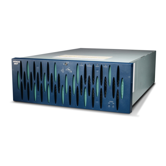
Page 26: Ams 2100 Base Unit
AMS 2100 base unit The Hitachi AMS 2100 storage system (model RKS) (hereafter referred to as AMS 2100) includes a base unit and from 0 to 7 expansion units or from from 0 to 3 high-density expansion units. • The base unit contains from 4 to 15 SAS and/or SATA disk drives, two redundant controllers, two redundant power supplies, and two cache battery backup units. -
Page 27: Ams 2300 Base Unit
• The AMS 2300 is externally identical to the AMS 2100 except that it has four Fibre Channel ports on each of the two controllers instead of two, or two iSCSI ports, as shown in the figure below. Internally, it has a... - Page 28 1–8 Introduction Hitachi AMS 2100/2300 Storage System Hardware Guide...
-
Page 29: Expansion Unit
2100/2300 expansion unit. The front bezel has been removed in this photo. Expanded views are shown in Chapter 4, Hardware components. Figure 1-5: AMS 2100 /AMS 2300 Expansion Unit Front and Rear Views 1–9 Introduction Hitachi AMS 2100/2300 Storage System Hardware Guide... -
Page 30: High Capacity Expansion Unit
High capacity expansion unit The Hitachi High-density Expansion Unit (Model RKAKX) contains from 4 to 48 SATA disk drives, four redundant power supplies, and four ENC control units (cards). The control units manage the drives and are also used to connect the expansion unit to the base unit and to other expansion units. -
Page 31: Features And Benefits
Fibre channel interface The AMS 2100 supports two Fibre Channel ports per controller, and the AMS 2300 supports 4 Fibre Channel ports per controller. The AMS2300 with an 8 Gbps Fibre Channel connection can transfer data between the host computer and the disk array at a maximum speed of 800 MB/s for one port. -
Page 32: Fibre Channel Cable
Point-to-Point • F-port High-speed Fibre With the 4 Gbps Fibre Channel connection, the AMS 2100 Data Transfer Channel array can transfer data between the host computer and the array at a maximum speed of 400 MB/sec on each port. An 8 Gbps Fibre Channel connection is possible with the AMS 2300 array. -
Page 33: Iscsi Interface
Guide, MK-97DF8009. iSCSI interface The AMS 2100/2300 provides two iSCSI ports per controller (4 total per base unit). To convert a base unit from Fibre Channel to iSCSI, replace both controllers and install the firmware on them. The same firmware supports both Fibre Channel and iSCSI units. - Page 34 Ping iSCSI You can ping the network to verify whether the device at a specified address and the AMS 2100/2300 can communicate with IP network. This function specifies the address that Navigator 2 sends the ping from the iSCSI interface, and then displays a response. However, pinging an unreachable address might cause a delay and time- out of the host I/O processing on the controller.
-
Page 35: Scalability
• A single AMS 2100 base unit that contains from 4 to 15 disk drives, or a larger system using a single AMS 2100 base unit with 4-15 drives and attached expansion units and/or high-density expansion units. - Page 36 Mountable Number of Disk Drives RKAK RKAKS Basic Chassis mounted mounted mountable (one unit) additonal additonal number of chassis chassis disk drives RKS/RKES RKEM For further details, see the following two tables. 1–16 Introduction Hitachi AMS 2100/2300 Storage System Hardware Guide...
- Page 37 1 in Unit A, and two drives installed in slots 0 and 1 in Unit B. Using an AMS 2000 rack, you can construct a system that meets your needs by combining base units and expansion units as shown in the following tables. Table 1-7: AMS 2100 High-density Expansion Unit Intermix Maximum Number High-density Expansion...
-
Page 38: Fibre Channel Interface
Up to 15 spare disks can be set up in any location with an AMS 2100 and up to 30 spare disk drives with an AMS 2300. •... -
Page 39: Iscsi Interface
300 (OM3) meters, or 82 (OM2) meters. High capacity cache The AMS 2100/2300 supports a maximum of 4 GB high capacity cache per control unit. This cache configuration supports immediate reporting to a host when data is written from the host to the cache. This is explained in detail in the next section. -
Page 40: Cache Specifications
Performance reporting and monitoring The Navigator 2 storage management software provides the capability to either monitor the disk array in real-time or collect historical data regarding the performance of the storage system. 1–20 Introduction Hitachi AMS 2100/2300 Storage System Hardware Guide... -
Page 41: Reliability, Availability, And Serviceability
Spare disks An AMS 2100 can include up to 15 spare disks per array. An AMS 2300 can include up to 30 spare disks per array. The AMS 2100/2300 arrays monitor the disk drives for potential failure. -
Page 42: Raid Implementations
RAID implementations The AMS 2100/2300 supports RAID 0, RAID 1+0, RAID 1, RAID 5, RAID 6, or an intermix, as described below. Table 1-10: RAID Implementations RAID Description Level RAID 0 group stripes data across all disk drives in the group to attain higher throughput. -
Page 43: Open Systems Features And Functions
RAID 1+0 2D+2D to 7D+7D 2D+2D to 8D+8D Open systems features and functions The AMS 2100/2300 offers many features and functions specifically for the open-systems environment. The AMS 2100/2300 also supports important open-system functions such as fibre-channel arbitrated-loop (Fibre Channel-AL) and fabric topologies, command tag queuing, multi-initiator... -
Page 44: Data Management Features And Functions
Data management features and functions The AMS 2100/2300 includes several high-performance features that implement easy and fast data management. These features are described Table 1-12. Table 1-12: Data Management Features and Functions Feature Description Cache Residency The Cache Residency Manager feature makes data of specific... - Page 45 Data At Rest Encryption The Data At Rest Encryption allows a self encrypting drive with the function encrypting/decoding the stored data to be used as an installed disk drive for encrypting the data to be stored in the array. 1–25 Introduction Hitachi AMS 2100/2300 Storage System Hardware Guide...
-
Page 46: Copy Solution Features And Functions
Copy solution features and functions The AMS 2100/2300 supports several copy solutions as described in the following table. Table 1-13: Copy Solution Features and Function Feature Description TrueCopy Remote The TrueCopy remote replication function continuously Replication synchronizes the data on two arrays connected by a Fibre Channel interface, ensuring that both arrays always contain the same data. -
Page 47: Failure Monitoring Features And Functions
Failure monitoring features and functions The AMS 2100/2300 supports failure monitoring solutions, as described in Table 1-15. Table 1-15: Failure Monitoring Features and Functions Feature Description SNMP Agent Support The SNMP Agent Support Function reports occurrences of Function failure to the workstation for monitoring the network via the SNMP (Simple Network Management Protocol) of the open platform. -
Page 48: Email Alert Notification
Email alert notification When a failure occurs in an AMS 2100/2300 and error monitoring is enabled, the Navigator 2 email alert feature sends email messages containing failure information to up to three previously registered email addresses when a failure has occurred in the array. The email alert feature detects failures at the instant they happen, and immediately sends failure notices to the designated recipients. -
Page 49: Long Term Array Storage
The cache backup batteries in a Hitachi AMS 2000 Family Storage System array cannot hold a charge indefinitely. If you do not use an AMS 2100/2300 for six months or more, move the batteries to a system that is being used, or turn the array on for at least 24 hours once every six months. - Page 50 1–30 Introduction Hitachi AMS 2100/2300 Storage System Hardware Guide...
-
Page 51: Functional And Operational Characteristics
Functional and operational characteristics This chapter describes the basic features of the Hitachi AMS 2000 Family Storage System. It contains the following key topics: Overview of the AMS 2100/2300 storage system Array specifications Fibre channel interface iSCSI interface ... -
Page 52: Overview Of The Ams 2100/2300 Storage System
Overview of the AMS 2100/2300 storage system Architecture and components The system architecture of the AMS 2100 and AMS 2300 are similar, as is their physical construction. Both arrays contain many of the same components. The block diagrams in this section show the differences and similarities of the two units. - Page 53 Figure 2-1: AMS 2100 Configuration Block Diagram Table 2-1: AMS 2100 Configuration Block Diagram Item Description Item Description Item Description Backup Battery #0 Host System SAS/SATA Control Backs up the cache in control unit 0 Fibre Channel Backup Battery #1 Interface OR iSCSI ...
-
Page 54: Ams 2300 Configuration Architecture
Figure 2-2 shows the configuration block diagram of an AMS 2300 array. Table 2-2 provides a description of each numbered part. Figure 2-2: AMS 2300 Configuration Block Diagram 2–4 Functional and operational characteristics Hitachi AMS 2100/2300 Storage System Hardware Guide... -
Page 55: Expansion Unit Architecture
Figure 2-3 shows the configuration block diagram of an AMS 2000 Family expansion unit. Table 2-3 provides a description of each numbered part. Figure 2-3: Expansion Unit Block Diagram 2–5 Functional and operational characteristics Hitachi AMS 2100/2300 Storage System Hardware Guide... -
Page 56: Modular 2U Sas Expansion Unit Rkaks Architecture
The following illustration shows the configuration block diagram of an AMS 2000 Family Modular 2U SAS RKAKS expansion unit. *1 Disk Drive: DF-F800-AMF300, DF-800-AMF600 Table 2-4: System Configuration of the RKAKS 2–6 Functional and operational characteristics Hitachi AMS 2100/2300 Storage System Hardware Guide... -
Page 57: High-Density Expansion Unit Architecture
The following illustration shows the configuration block diagram of an AMS 2000 Family high-density expansion unit. The table following the illustration provides a description of each numbered part. Figure 2-4: High-capacity Expansion Unit Block Diagram 2–7 Functional and operational characteristics Hitachi AMS 2100/2300 Storage System Hardware Guide... -
Page 58: Array Specifications
The AMS 2100 array can be configured with one AMS 2100 base unit and from 0 to 7 expansion units or a maximum of one high-density expansion unit for a maximum total of 120 disk drives. - Page 59 1 k byte =1,024 bytes, which displays on the PC you are using. The RAID group capacity values displayed in the Hitachi Storage Navigator Modular 2 are calculated as 1 k byte =1,024 bytes. See the Preface of this manual for more information on storage capacity values.
-
Page 60: Fibre Channel Interface
Storage Platform/ Network Storage Controller and the AMS 2100/AMS 2300 to the fixed transfer rate (the same value for the Universal Storage Platform and the AMS 2100/2300 selecting any one of 1 Gbps, 2 Gbps, or 4 Gbps). Table 2-7: Fibre Channel Transfer Rates... -
Page 61: Iscsi Interface
Connector: RJ-45 For the physical port of the switch to be connected directly with the host and the iSCSI port of the AMS 2100/2300, do not set the Spanning Tree protocol function to ON. It may cause communications interference. For the 10G bps iSCSI, use the following optical cable: •... -
Page 62: Required Parts
Required parts Table 2-8 describes the required components for AMS 2100/2300 arrays. Table 2-8: AMS 2100/2300 Required Parts Name Model Components Base Unit Frame (1), Front Bezel (1), Panel (1), Backup battery unit (2), DF-800-RK2 AC cable J2H (2), Power unit (2) (RK2) 3.5-type Disk drive (142.61 GB) installed in a canister. - Page 63 1 k byte =1,024 bytes. The RAID group capacity values displayed in the Hitachi Storage Navigator Modular 2 are calculated as 1 k byte =1,024 bytes. See the Preface of this manual for more information on storage capacity values.
-
Page 64: Optional Parts
Optional parts Table 2-9 describes the optional components for AMS 2100/2300 arrays. Table 2-9: AMS 2100/2300 Optional Parts Classification Part Number Name Description Spare Disk Disk drive Refer to disk drive information. Additional Disk Disk drive Refer to disk drive information. - Page 65 Table 2-9: AMS 2100/2300 Optional Parts (Continued) Classification Part Number Name Description DF-F800-J1H Power cable 2.5 m, 2-pole power cable with grounding terminal (AC 125 V, 13 A or 15 DF-F800-J2H Power cable 2.5 m, 2-pole power cable with grounding terminal (AC 250 V, 13 A or 15...
- Page 66 Table 2-9: AMS 2100/2300 Optional Parts (Continued) Classification Part Number Name Description FICSMSCLC010M.P LC/LC Fibre FICON Single Mode 9UM Cable 10M JZ-050LL005PC.P LC/LC Duplex Fibre Optic 50UM Cable 5M JZ-050LL010PC.P LC/LC Duplex Fibre Optic 50UM Cable Fibre Channel interface Cable Fibre Channel JZ-050LL025PC.P...
- Page 67 Table 2-9: AMS 2100/2300 Optional Parts (Continued) Classification Part Number Name Description This feature reduces power consumption Power Saving by turning off the drive motors in a selected group of drives in the array. Protects the disk array data and LUNs...
-
Page 68: Accessory Parts
Accessory parts Table 2-10 lists the accessory parts for the AMS 2100/2300. Table 2-10: AMS 2100/2300 Accessory Parts Classification Model Name Specification DF-F800-J1H 2.5 m, 2-pole power cable with grounding terminal (AC 125 V, 13 A or 15 A) DF-F800-J2H 2.5 m, 2-pole power cable... - Page 69 Table 2-10: AMS 2100/2300 Accessory Parts (Continued) Classification Model Name Specification DF-F800-VRC2 Remote adapter For control of Remote cable adapter, 2 m DF-F800-VRC5 Remote adapter For control of Remote cable adapter, 5 m Remote adapter DF-F800-VRC10 Remote adapter For control of Remote...
- Page 70 2–20 Functional and operational characteristics Hitachi AMS 2100/2300 Storage System Hardware Guide...
-
Page 71: Getting Started
Getting started This chapter provides an overview of the tasks to install and configure a Hitachi Adaptable Modular Storage 2100/2300 Storage System. It covers the following key topic: Task roadmap 3–1 Getting started Hitachi AMS 2100/2300 Storage System Hardware Guide... -
Page 72: Task Roadmap
Task roadmap Table 3-1 lists and describes the required and optional tasks that users should and can do to install, set up, configure, and manage the AMS 2100/ 2300 array. Table 3-1: Procedures for Installing and Configuring the AMS 2100/2300... -
Page 73: Hardware Components
This chapter describes the components, controls, connectors and indicators of the Hitachi Adaptable Modular Storage 2100/2300 Storage System. It covers the AMS 2100 and AMS 2300 base units, the expansion unit, and the high-density expansion unit, and explains the functions of various parts of the units. This... -
Page 74: The Base Unit
The following illustration shows the front of a base unit with the decorative bezel installed (upper photo) and removed in the lower photo, with the components on the front of the unit exposed. Both the AMS 2100 and the AMS 2300 unit models are the same on the front. -
Page 75: Disk Drives
Each slot can accommodate one SATA drive or one SAS drive. Disk drive configurations The following requirements are for both the AMS 2100 and the AMS 2300 base units. See the section on expansion units for configuration information about them. -
Page 76: Base Unit Status Leds
Base unit status LEDs Front panel The upper right edge of the front of the AMS 2100/2300 base unit has four LEDs that indicate the status of the array. Also built into the chassis are two status LEDs for each disk drive. In addition, the Cache Backup battery has two status LEDS. -
Page 77: Rear Panel
Fast Blink condition Rear panel The rear panel of the AMS 2100/2300 base unit has several LEDs that indicate the status of the power supplies and control units. These LEDs are explained as part of the descriptions of the Base unit power supplies... - Page 78 • On: normal status Ready LED • Low-speed blinking (1 blink per second): The battery is not fully charged. (green) • Off or high-speed blinking (8 blinks per second): Abnormal status 4–6 Hardware components Hitachi AMS 2100/2300 Storage System Hardware Guide...
-
Page 79: Switch Panel
Ready light changes from blinking to steady ON. Important! Read chapter 6, Power On and Off Procedures before turning the power on or off. 4–7 Hardware components Hitachi AMS 2100/2300 Storage System Hardware Guide... -
Page 80: Base Unit Rear Panel
Figure 4-6 shows the main hardware components on the rear side of a Fibre Channel AMS 2100 base unit. Except for the number of Fibre Channel host connectors on the controllers, the Fibre Channel version of the AMS 2100 rear panel is identical to the AMS 2300. The rear panels of the iSCSI versions of the two models are the same. -
Page 81: Base Unit Power Supplies
Each power supply contains a power receptacle that must be connected to a working AC power source using the supplied AC power cable. NOTE: Hitachi Data Systems recommends that each power supply in the base unit be connected to a different AC source in the rack. If one source fails, the other source continues to supply power to the other power supply. -
Page 82: Safety Lock
NOTE: Hitachi Data Systems recommends that you install the cable retainer to prevent the power cable from accidentally being disconnected from the power supply. -
Page 83: Ams 2100 Fibre Channel Control Unit
The upper control unit is identical but is installed in the base unit upside down. Figure 4-8: Control Unit Connectors and LEDs (Fibre Channel AMS 2100) Table 4-9: Control Unit Connectors and LEDs (Fibre Channel AMS 2100) Item Description Item... -
Page 84: Ams 2100 Rev1 Fibre Channel Control Unit Rks
RKS base unit. The uppder control unit is identical but is installed in the base unit upside down. Figure 4-9: AMS 2100 Rev1 Disk Drive Status LEDs Table 4-10: AMS 2100 Rev1 Base Unit Status LEDs (front panel) Item Function... -
Page 85: Ams 2100 Rev2 Fibre Channel Control Unit Rkes
Figure 4-10 Table 4-11 shows the lower control unit of an AMS 2100 Rev2 /RKES base unit. The upper control unit is identical but is installed in the base unit upside down. Figure 4-10: RKES Disk Drive Status LED Table 4-11: RKES Disk Drive Status LEDs (front panel)s... - Page 86 ON: status of the interface is normal. (green) (red) ON: status of the interface is normal. ON: the host connector is abnormal (GP0 LED and GP1 LEDs become red at the same time. (red) 4–14 Hardware components Hitachi AMS 2100/2300 Storage System Hardware Guide...
-
Page 87: Ams 2300 Fibre Channel Control Unit
ACT LED (yellow) indicates data is being transferred. LOC LED (orange) LINK LED (green) When ON, Table 4-16 on indicates that the link status page 4-21 is normal. 4–15 Hardware components Hitachi AMS 2100/2300 Storage System Hardware Guide... -
Page 88: Ams 2300 Rev2 Fibre Channel Control Unit Rkm
1.Fibre Channel AMS 2300 supports uninterrupted power supplies (UPS). The location of this connector may be slightly different than shown here, depending on the model of the controller. For more information, contact your Hitachi Data Systems representative, or refer to the UPS documentation. -
Page 89: Ams 2300 Rev2 Fibre Channel Control Unit Rkem
As described earlier, the controllers in each model base unit are different. The main differences between the control units is the number of Fibre Channel ports and the amount of cache memory (RAM) installed in the 4–17 Hardware components Hitachi AMS 2100/2300 Storage System Hardware Guide... - Page 90 Figure 4-13 Table 4-14 shows the lower control unit of an AMS 2100 /RKES base unit (Rev2). The upper control unit is identical but is installed in the base unit upside down. Figure 4-13: AMS 2300 Rev2 RKEM LEDs Table 4-14: AMS 2300 Rev2...
-
Page 91: Ams 2100/2300 Iscsi Control Unit
(red) AMS 2100/2300 iSCSI control unit The iSCSI AMS 2100/2300 control units are externally the same and are shown in the following illustration. The only difference between them is the amount of RAM (cache memory) each contains. See... - Page 92 1.AMS 2100/2300 iSCSI supports uninterrupted power supplies (UPS). The location of this connector may be slightly different than shown here, depending on the model of the controller. For more information, contact your Hitachi Data Systems representative, or refer to the UPS documentation.
- Page 93 1.When blinking fast, the LED is on for 400ms and off for 200 ms for each fast blink. After the number of fast blinks has completed, the LED ID off for one second. 4–21 Hardware components Hitachi AMS 2100/2300 Storage System Hardware Guide...
-
Page 94: Fibre Channel Host Connectors
Fibre channel host connectors Each of the two AMS 2100 control units has two Fibre Channel data ports (total of 4 ports per array). Each of the two AMS 2300 control units has four Fibre Channel data ports (total of 8 ports per array). Each data port is part of a device called a host connector. -
Page 95: 10/100 Ethernet Management Port
Link light comes on steady. The Activity LED lights when data is being transferred to or from the port. NOTE: If you use Navigator 2 to configure an AMS 2100/2300 array to send email alerts, be sure the management port can communicate via Ethernet with your mail server. - Page 96 Figure 4-16: Connecting a Laptop to a Management Port 4–24 Hardware components Hitachi AMS 2100/2300 Storage System Hardware Guide...
-
Page 97: Standard Expansion Unit
Disk drive configurations on page RAID implementations on page 1-22 are followed. Both the AMS 2100 and the AMS 2300 base units use the same expansion unit, although the number of expansion units that they can use is different. •... -
Page 98: Disk Drives
1. Enlarged views are shown on pages 4-18 and 4-19. Disk drives As shown in #1 in Figure 4-11 above, an AMS 2100/2300 expansion unit has 15 drive slots in the front of the array. Each slot can accommodate one SATA drive or one SAS drive. -
Page 99: Disk Drive Status Leds
Lights or flashes when the drive is Lights when the drive has a operating and is being read from or serious error. written to. It indicates that the disk drive is operational. 4–27 Hardware components Hitachi AMS 2100/2300 Storage System Hardware Guide... -
Page 100: Expansion Unit Status Leds
Expansion unit status LEDs The upper right edge of the front of the AMS 2100/2300 expansion unit contains two LEDs that indicate the status of the unit. The table below describes the array status LEDs and their functions. Table 4-20: Expansion Unit Status LEDs... -
Page 101: Expansion Unit Rear Panel
Expanded views of the expansion unit and detailed descriptions are located on the following pages. Daisy-chain Connectors LEDs Power Power Receptacle Receptacle LEDs Figure 4-21: Rear View of the Expansion Unit 4–29 Hardware components Hitachi AMS 2100/2300 Storage System Hardware Guide... -
Page 102: Expansion Unit Power Supply
Ready LED (green). on each power supply blinks when the corresponding power receptacle is connected to a working AC outlet, even if an AMS 2100/2300 array is not turned on; otherwise, the LED is OFF. Power receptacles Each power supply contains a power receptacle that must be connected to a working AC power source using the supplied AC power cable. -
Page 103: Safety Lock
NOTE: Hitachi Data Systems recommends that you install the cable retainer to prevent the power cable from accidentally being disconnected from the power supply. -
Page 104: Enc Unit Rkak
1.When blinking fast, the LED is on for 400ms and off for 200 ms for each fast blink. After the number of fast blinks has completed, the LED id off for one second. 4–32 Hardware components Hitachi AMS 2100/2300 Storage System Hardware Guide... -
Page 105: Modular 2U Sas Expansion Unit
Modular 2U SAS expansion unit A modular 2U SAS expansion unit (factory designation RKAKS) provides additional storage capabilities for the base units.For the AMS 2100 and the AMS 2300, this unit can install a maximum of 24 SAS disk drives. An expansion unit provides additional storage space and can connect the base unit to additional expansion units or high-density expansion units. -
Page 106: Modular 2U Sas Expansion Unit Disk Drive Leds
These LEDs indicate the operational status of the power supply, and are described in Table 4-28 on page 4-35. Figure 4-27: Modular 2U SAS expansion unit power supply LEDs 4–34 Hardware components Hitachi AMS 2100/2300 Storage System Hardware Guide... -
Page 107: Modular 2U Sas Expansion Unit Enc Unit
PATH0 (in) side LED (green) ON: The IN side is linked up PATH0 (out) side LED ON: The OUT side is linked up (green) Table 4-29: Modular 2U SAS expansion unit ENC Unit 4–35 Hardware components Hitachi AMS 2100/2300 Storage System Hardware Guide... -
Page 108: High-Density Expansion Unit
ENC unit in the high-density expansion unit. Both the AMS 2100 and the AMS 2300 base units use the same high-density expansion unit. They each support only one high-density expansion unit. NOTE: Disk drives are installed, removed, and replaced from the top of the high-density expansion unit. -
Page 109: High-Density Expansion Unit Front Panel
Normal operation; the section is fully operational. Slow Blink POWER The firmware download is complete. (green) The firmware is downloading (do not turn off the Fast Blink array). 4–37 Hardware components Hitachi AMS 2100/2300 Storage System Hardware Guide... -
Page 110: High-Density Expansion Unit Rear Panel
ENC Unit A0 OUT Power Supply 0A ENC Unit B1 IN ENC Unit A1 IN Power Supply 1A ENC Unit B1 OUT ENC Unit A1 OUT 4–38 Hardware components Hitachi AMS 2100/2300 Storage System Hardware Guide... -
Page 111: High-Density Expansion Unit Power Supply
ON when the poser supply is operational. even if the AMS 2100/2300 array is not turned Power Receptacle (see next page) Lock Lever Figure 4-32: High-density Expansion Unit Power Supply Components 4–39 Hardware components Hitachi AMS 2100/2300 Storage System Hardware Guide... - Page 112 Each power supply contains a power receptacle that must be connected to a working AC power source using the supplied AC power cable. NOTE: Hitachi Data Systems recommends that each power supply in the base unit be connected to a different AC source in the rack. If one source fails, the other source continues to supply power to the other power supply.
-
Page 113: High-Density Expansion Unit Enc Connectors
OUT connector. Figure 4-34 shows the connectors removed from the high-density expansion unit and open to show how the ENC cable is connected inside. Figure 4-34: ENC Connectors 4–41 Hardware components Hitachi AMS 2100/2300 Storage System Hardware Guide... -
Page 114: High-Density Expansion Unit Top View
Disk Drive Filler (must be in all slots Power Supply Area that do not have disk drives installed.) Disk Drive. See Disk Drive ENC Unit (four required) Configurations following this table. 4–42 Hardware components Hitachi AMS 2100/2300 Storage System Hardware Guide... -
Page 115: Disk Drive Configurations
48 drives are not installed. The following requirements for the high-density expansion unit apply whether it is connected to an AMS 2100 or to an AMS 2300. • All disk drives in this unit must be SATA drives. - Page 116 Figure 4-37: Alarm LED Locations 4–44 Hardware components Hitachi AMS 2100/2300 Storage System Hardware Guide...
-
Page 117: High-Density Expansion Unit Enc Card
Voltage on the control unit is abnormal. (Reset of the 6 (slow) control unit is not canceled) Boot section error in the ENC firmware, a RAM error, or ENC hard configuration error. 4–45 Hardware components Hitachi AMS 2100/2300 Storage System Hardware Guide... - Page 118 1.When blinking fast, the LED is on for 400ms and off for 200 ms for each fast blink. After the number of fast blinks has completed, the LED id off for one second. 4–46 Hardware components Hitachi AMS 2100/2300 Storage System Hardware Guide...
-
Page 119: Installation
Installation This chapter describes the procedures to install a Hitachi AMS 2100/2300 Storage System. The installation procedures include instructions to connect data, control, and power cables to the units, as well as references to information to install additional components. It includes the following key... -
Page 120: Chapter Overview And Task List
Install the array in a rack. 5-30 Configure and manage your storage. Consult the Hitachi AMS 2000 Family iSCSI Host Installation Guide or Hitachi AMS 2000 Family Fibre Channel Host Installation Guide. Safety considerations Personal safety Observe the following guidelines to ensure your safety. Failure to follow these guidelines could result in bodily injury and/or damage to the array or its components. -
Page 121: Electrical Safety Guidelines
(LAN and Fibre Channel cables can be installed or removed with the power on.) • When working with high voltage, do not work alone. Work with another person who can immediately turn off the power in an emergency. 5–3 Installation Hitachi AMS 2100/2300 Storage System Hardware Guide... -
Page 122: Handling Of Cables On The Floor
• Heat. Do not install the unit in a rack which has less than the specified cooling. The AMS 2100/2300 has heat sensors which will cause the unit to shut down if the internal temperature exceeds the specifications. See the Hitachi AMS 2000 Family Storage System Reference Guide for details. -
Page 123: Warning Labels
Figure 5-1: Warning and Safety Labels (Base Unit) label is affixed at location (a) or (b). Either (I) or (II) is affixed. 5–5 Installation Hitachi AMS 2100/2300 Storage System Hardware Guide... -
Page 124: Warning And Safety Labels (Expansion Unit)
Figure 5-2: Warning and Safety Labels (Expansion Unit) label is affixed at location (a) or (b). Either (I) or (II) is affixed 5–6 Installation Hitachi AMS 2100/2300 Storage System Hardware Guide... -
Page 125: Warning And Safety Labels (Modular 2U Sas Expansion Unit)
Warning and safety labels (modular 2U SAS expansion unit) Figure shows the location and content of the warning and safety labels on the expansion unit. Figure 5-3: Warning and Safety Labels (modular 2U SAS expansion unit). 5–7 Installation Hitachi AMS 2100/2300 Storage System Hardware Guide... -
Page 126: Warning And Safety Labels (High-Density Expansion Unit)
Figure 5-4: Warning and Safety Labels (High-density Expansion Unit) label is affixed at location (a) or (b). 5–8 Installation Hitachi AMS 2100/2300 Storage System Hardware Guide... -
Page 127: Disk Drives
High-density Expansion Unit disk drive. Figure 5-6: High-density Expansion Unit Disk Drive The figure below shows the location of the label on the modular 2U SAS Expansion Unit disk drive. 5–9 Installation Hitachi AMS 2100/2300 Storage System Hardware Guide... -
Page 128: Battery Unit
Figure 5-7: Battery Unit Power supply Figure 5-8 shows the location of the label on the Power Supply for the Base Unit. Figure 5-8: Power Supply Label Location for the Base Unit 5–10 Installation Hitachi AMS 2100/2300 Storage System Hardware Guide... - Page 129 Figure 5-10: Power Supply Label Location for the Modular 2U SAS Expansion Unit Figure 5-11 shows the location of the label on the Power Supply for the High-density Expansion Unit. Figure 5-11: Power Supply Label Location for the High-density Expansion Unit 5–11 Installation Hitachi AMS 2100/2300 Storage System Hardware Guide...
-
Page 130: Control Unit
Control unit Figure 5-12 shows the label locations on the AMS 2100 and 2300 Control Unit. AMS 2100 AMS 2300 Figure 5-12: Control Unit Label Location 5–12 Installation Hitachi AMS 2100/2300 Storage System Hardware Guide... -
Page 131: Cache Memory
Figure 5-13: Cache Memory Label Location Interface board Figure 5-14 shows the location (a) or (b) of the labels on the FC Interface Board. Figure 5-14: Fibre Channel Interface Board Label Location 5–13 Installation Hitachi AMS 2100/2300 Storage System Hardware Guide... -
Page 132: Host Connector
10 Gbps iSCSI Interface Board. Figure 5-16: 10 Gbps iSCSI Interface Board Label Location Host connector Figure 5-17 shows the location of the label on the Host Connector. Figure 5-17: Host Connector Label Location 5–14 Installation Hitachi AMS 2100/2300 Storage System Hardware Guide... -
Page 133: Enc Unit
ENC unit Figure 5-18 shows the location of the label on the ENC Unit of the Expansion Unit. Figure 5-18: ENC Unit Label Location for the Expansion Unit 5–15 Installation Hitachi AMS 2100/2300 Storage System Hardware Guide... -
Page 134: Enc Cable
Figure 5-20: ENC Unit Label Location for the High-density Expansion Unit ENC cable Figure 5-21 shows the location of the label on the ENC Cable. Figure 5-21: ENC Cable Label Location 5–16 Installation Hitachi AMS 2100/2300 Storage System Hardware Guide... -
Page 135: Cable Holder
Cable holder Figure 5-22 shows the locations of the labels (a) or (b) on the Cable Holders. Figure 5-22: Cable Holder Label Locations 5–17 Installation Hitachi AMS 2100/2300 Storage System Hardware Guide... -
Page 136: Preinstallation Requirements
Ensure that the requirements in this section are completed before installing an array. Site considerations Ensure that the server room or other facility where the AMS 2100/2300 is installed complies with the electrical specifications and environmental specifications listed in the Hitachi AMS 2000 Family Storage System Reference Guide and also in the Hitachi AMS 2000 Family Site Preparation Guide. -
Page 137: Floor Load Rating
Preparation Guide, MK-98DF8149EN for information about the array and rack weights. Installation area and service clearance Please see the information and specifications in the Hitachi AMS 2100/2300 Site Preparation Guide before installing an AMS 2100/2300 storage system. • Installation area means a large enough area to assure the intake and exhaust air. -
Page 138: Installation Configurations
Installation configurations The AMS 2100/2300 is mounted in an AMS 2000 19-inch rack with extra depth. In one rack: • One RKS/RKES connects up to seven RKAKs (Disk Drive: Maximum of 120 units) at a maximum of 330.7 T bytes RAID5 (14D+1P) (using the 3,000 G disk drive). - Page 139 The system configuration which one RKM connect up to 15 RKAK (Disk Drive: Maximum of 240 units) can be made. • When connecting RKAKX to the RKEM, a system can be mounted up to 255 Disk Drives. 5–21 Installation Hitachi AMS 2100/2300 Storage System Hardware Guide...
-
Page 140: Minimum Configurations
Minimum configurations The minimum configurations of the AMS 2100 and AMS 2300 are: • AMS 2100: one base unit containing four SATA or four SAS disk drives • AMS 2300: one base unit containing four SATA or four SAS disk drives... -
Page 141: Maximum Configurations
The maximum configurations of the AMS 2100 and AMS 2300 are: • AMS 2100: one base unit (15 disk drives) and either seven expansion units (105 disk drives) or one high-density expansion unit (48 disk drives). The maximum number of disk drives, including the base unit is 120. -
Page 142: Installing An Ams 2100/2300
Installing an AMS 2100/2300 Installation road map The following table lists the steps to install an AMS 2100/2300 and provides links and page numbers where the detailed steps are located. Table 5-3: Installation Tasks Step Description Page Unpack the Array 5-24 ... - Page 143 The array within the outer package is shown in the following illustration. Complete the following steps to unpack an AMS 2100/2300 array. 1. Remove the outer package and packing materials. 2. Take the array out of the polyethylene bag.
- Page 144 Base Unit or Shipping Accessory Box Guide Expansion Unit container License Buffer Pad Agreement (upper) Buffer Pad Front Bezel Desiccant (lower) 5–26 Installation Hitachi AMS 2100/2300 Storage System Hardware Guide...
-
Page 145: Checking The Contents Of The Package
Be sure to keep the key for the front bezel supplied with the array. The key for the front bezel is used for security control and parts replacement. The same key fits all AMS 2100/2300 base and expansion units. Figure 5-24: Locations of Array Serial Number Markings 5–27... -
Page 146: Removing The Front Bezel
3. Disengage the two hooks of the front bezel from the slots on the array chassis by shifting the bezel to the left, and remove the bezel. See Figure 5-26. Also, see the illustrations in Chapter 4 for more details. 5–28 Installation Hitachi AMS 2100/2300 Storage System Hardware Guide... - Page 147 Figure 5-26: Removing the Front Bezel Table 5-5: Removing the Front Bezel Item Description Item Description Item Description Front Bezel Hook Ball Catches 5–29 Installation Hitachi AMS 2100/2300 Storage System Hardware Guide...
-
Page 148: Removing The Front Bezel Of The Modular 2U Sas Expansion Unit
Align the gaskets with the front and rear edges of the unit. 3. Install the array in the rack. See Mounting the array on the next page 5–30 Installation Hitachi AMS 2100/2300 Storage System Hardware Guide... - Page 149 Back end of the top Front end of the top Frame top of the frame of the frame EMI gasket Figure 5-28: Position for Attaching EMI Gasket (Base Unit) 5–31 Installation Hitachi AMS 2100/2300 Storage System Hardware Guide...
- Page 150 Figure 5-29: Position for Attaching an EMI Gasket (Expansion Unit) Figure 5-30: Position for Attaching an EMI Gasket (RKAKS Expansion Unit) 5–32 Installation Hitachi AMS 2100/2300 Storage System Hardware Guide...
-
Page 151: Mounting The Array
It could cause serious injury or damage if it falls. • Hitachi Data Systems recommends using mechanical lifting equipment to help install the array. However, the equipment should be operated only by trained and qualified personnel. -
Page 152: Fastening The Array To The Rack
5-32, fasten the rear side of the array to the rack rails. 3. Shift each of the two stoppers in the direction shown by the arrow and make it contact the frame. 4. Tighten the binding screws. 5–34 Installation Hitachi AMS 2100/2300 Storage System Hardware Guide... -
Page 153: Connecting Cables
Before connecting power cables to the array, make sure that the circuit breakers on the PDBs (power distribution busses) are turned OFF. 5–35 Installation Hitachi AMS 2100/2300 Storage System Hardware Guide... - Page 154 If it is necessary to bend an ENC cable to connect it, keep the bend radius as large as practical, and not less than 30 mm. This prevents excessive stress on the cable and the connector. 5–36 Installation Hitachi AMS 2100/2300 Storage System Hardware Guide...
- Page 155 CAUTION! To prevent electromagnetic interference from a power cable, to the signals in an ENC cable, do not route power cables near an ENC cable. 5–37 Installation Hitachi AMS 2100/2300 Storage System Hardware Guide...
- Page 156 Figure 5-34: Connecting ENC Cables from an AMS 2100 to the Expansion Units 5–38 Installation Hitachi AMS 2100/2300 Storage System Hardware Guide...
- Page 157 Figure 5-35: Connecting ENC Cables from an AMS 2300 to the Expansion Units 5–39 Installation Hitachi AMS 2100/2300 Storage System Hardware Guide...
- Page 158 Description Lock Tab (pull tab Diamond stamp Circle stamp on to unlock connector on controller / ENC IN end of before unplugging ENC OUT end of cable. cable 5–40 Installation Hitachi AMS 2100/2300 Storage System Hardware Guide...
- Page 159 3. Connect the ENC cable to the control unit. 4. Route the cable through the cable routing bars to the appropriate high- density expansion unit. See Figure 5-38 and the diagrams in the installation chapter in the maintenance manual. 5–41 Installation Hitachi AMS 2100/2300 Storage System Hardware Guide...
- Page 160 ENC units. 5. Open the lock lever on the ENC cable holder and slide the cable holder into the appropriate slot on the high-density expansion unit. See Figure 5-39. 5–42 Installation Hitachi AMS 2100/2300 Storage System Hardware Guide...
- Page 161 7. Push inward on the lock lever to close it. Ensure that the lock button snaps into place and locks the lever closed. Cable routing diagrams The following diagrams show examples of how to connect ENC cables from an AMS 2100/2300 to a variety of expansion unit and high-density expansion unit configurations. 5–43 Installation...
- Page 162 Figure 5-40: Connecting ENC Cables, AMS 2100/2300 and Three High- density Expansion Units 5–44 Installation Hitachi AMS 2100/2300 Storage System Hardware Guide...
- Page 163 Figure 5-41: Connecting ENC Cables, AMS 2100/2300, one Expansion Unit, and Three High-density Expansion Units 5–45 Installation Hitachi AMS 2100/2300 Storage System Hardware Guide...
- Page 164 Figure 5-42: Connecting ENC Cables, AMS 2100/2300, two Expansion Units, and three High-density Expansion Units 5–46 Installation Hitachi AMS 2100/2300 Storage System Hardware Guide...
- Page 165 Figure 5-43: Connecting ENC cables to the RKH/RKEH and 20 RKAKS 5–47 Installation Hitachi AMS 2100/2300 Storage System Hardware Guide...
-
Page 166: Connecting A Lan Cable
The default IP address for the user LAN port on the control unit #0 is 192.168.0.16. The default IP address for the user LAN port on the control unit #1 is 192.168.0.17. Figure 5-44: Connecting the LAN Cable 5–48 Installation Hitachi AMS 2100/2300 Storage System Hardware Guide... -
Page 167: Connecting Power Cables
Limit the load on each PDB in the rack to 8 amps. Use the following values to calculate the load: Table 5-10: AMS 2100/2300 Power Requirements Unit Current at 100 - 120VAC AMS 2100 Base Unit 3.8 Amps 5–49 Installation Hitachi AMS 2100/2300 Storage System Hardware Guide... - Page 168 3. Recheck the power cable plug to make sure it is still secure in the PDB and that it has not become loosened during the cable routing. See Figure 5-45. Figure 5-45: Connecting Power Cables (Rack PDB) 5–50 Installation Hitachi AMS 2100/2300 Storage System Hardware Guide...
- Page 169 1. Connect the Fibre Channel cables from the host systems to the desired Fibre Channel ports (host connectors) on the AMS 2100/2300 control unit. Insert the connectors on the cables until they are securely fastened to the host connectors and the lock snaps into place.
- Page 170 • 1. Connect the iSCSI cables from the host systems to the desired iSCSI ports on the AMS 2100/2300 control unit. Insert the connectors until the lock snaps into place. Figure 5-47: iSCSI Interface Cable Connection Ports 2. Pull all the iSCSI cables into the rack passing them through the opening for cables on the bottom plate of the rack.
-
Page 171: Turning The Array On
2. Within 10 minutes after you remove the dummy disk drive, install a new disk drive in the empty slot. 3. Repeat steps 1 and 2 for each drive you add to the array. 5–53 Installation Hitachi AMS 2100/2300 Storage System Hardware Guide... -
Page 172: Installing A Disk Drive
(SAS/SATA), capacity, and speed for the array. 4. Insert the disk drive into the desired slot. a. Fit the disk drive in the guide rail of the AMS 2100/AMS 2300/ expansion unit (RKS/RKM/RKAK), and slide it in the direction shown by the arrow. -
Page 173: Attaching A Front Bezel
3. Engage the two hooks of the bottom of the front bezel into the slots on the array chassis. See Figure 5-49. 4. Push the top of the front bezel toward the chassis to engage it into the ball catches. Figure 5-49: Installing a Front Bezel 5–55 Installation Hitachi AMS 2100/2300 Storage System Hardware Guide... -
Page 174: Attaching A Modular 2U Sas Extension Unit Front Bezel
3. Engage the front bezel by pressing the right side of the front bezel to engage the hook of the front bezel with the ball catch (2). 4. Lock the front bezel with the key (3). 5–56 Installation Hitachi AMS 2100/2300 Storage System Hardware Guide... -
Page 175: Installing Storage Navigator Modular 2
Figure 5-50: Attaching the modular 2U SAS expansion unit Installing Storage Navigator Modular 2 Detailed information about Navigator 2, including features, installation instructions, and operation is described in Installing Navigator 2 (page 7- 13). 5–57 Installation Hitachi AMS 2100/2300 Storage System Hardware Guide... - Page 176 5–58 Installation Hitachi AMS 2100/2300 Storage System Hardware Guide...
-
Page 177: Power On/Off Procedures
Power On/Off procedures This chapter provides the procedures to apply power to and remove power from a Hitachi Adaptable Modular Storage 2100/ 2300 Storage System. The following topics are discussed: Task list Prerequisites Storage system power on ... -
Page 178: Task List
• Ensure that all prerequisite tasks have been completed and that the electrical and environmental operating requirements have been met. See below and the specifications listed in the Hitachi AMS 2000 Family Storage System Reference Guide. • If the array includes expansion units or high-density expansion units,... -
Page 179: Storage System Power On
NOTE: When the Main switch is toggled to the Standby position, power is still applied to the power supplies. To completely remove the power from the unit, remove both power cables from the unit or disconnect them from the power source. 6–3 Power On/Off procedures Hitachi AMS 2100/2300 Storage System Hardware Guide... -
Page 180: Power On Self Test
Power LED is on and the Ready light is blinking. The POST takes approximately four minutes under normal circumstances. When the POST is complete and the unit is ready for operation, the Ready light changes from blinking to steady ON. 6–4 Power On/Off procedures Hitachi AMS 2100/2300 Storage System Hardware Guide... -
Page 181: Expansion Units And High-Density Expansion Units
ON or OFF. AS with the base unit, the power supplies in the expansion units will remain in standby and the fans will continue to run at low speed. 6–5 Power On/Off procedures Hitachi AMS 2100/2300 Storage System Hardware Guide... -
Page 182: Recovering From A Power Outage
If the Alarm or Warning LED on the front panel lights instead of the Ready LED, see Troubleshooting based on LED indications on page 8-13 5. If host I/O activity was stopped, resume I/O activity to the array. 6–6 Power On/Off procedures Hitachi AMS 2100/2300 Storage System Hardware Guide... -
Page 183: Configuration
Configuration This chapter describes how to configure a Hitachi Adaptable Modular Storage 2100/2300 Storage System. Refer to the Host Configuration Guides for information about configuring the host system and for configuring storage on the host system. This chapter contains the following topics: Configuration tasks ... -
Page 184: Configuration Tasks
Configuration tasks This section describes the tasks required to configure an AMS 2100/2300 to store and manage the data from a host system. NOTE: • The response performance mode is enabled only when the segment size is 16 kB or less. Be careful when using it with Cache Partition Manager. -
Page 185: Supported Network Standards
Windows 7 or Windows Server 2008 R2 supports only Internet Explorer 8.0. Supported network standards The AMS 2100/2300 user LAN port supports the following network standards. Table 7-2: Supported Network Standards... -
Page 186: Precautions When Using The Ipv6 Protocol
Navigator 2 in the network environment in which SCCP is introduced, it is required to change the TCP port that Navigator 2 uses. Refer to the Hitachi Storage Navigator Modular 2 (for GUI) User's Guide or Hitachi Storage Navigator Modular 2 Command Line Interface (CLI) User’s Guide for the change method. -
Page 187: Ipv6 Link Local Address
Setting the IPv6 address Hitachi Data Systems recommends that you set the IPv6 address manually. If you obtain the IPv6 address automatically, since the IPv6 address is created based on the MAC address, the IPv6 address set to the array is changed automatically if the control unit is replaced due to a failure, etc. -
Page 188: Temporary Address
Connection method The following illustration shows an example of a connection between the AMS 2100/2300 and the computer in which Navigator 2 is installed on the host computer and not a separate management console. The following are notes regarding the above illustration: 1. -
Page 189: Communication Modes
3. The IPv6 multicast of the link local scope is used for the search array by the IPv6 address. When performing the search array, set up the array and the computer in which Hitachi Storage Navigator Modular 2 is installed in the same link. -
Page 190: Configuring An Ams 2100/2300
: Communication possible X : Communication not possible Configuring an AMS 2100/2300 This section explains how to set up and configure an AMS 2100/2300. Prerequisites Before using Navigator 2, please read the following notes and instructions. • If you are using Microsoft Windows, disable Windows power management to prevent the PC from entering the low power mode suspension state. -
Page 191: Configuration Roadmap
Hitachi Data Systems storage products, including the AMS 2100/2300. It consists of a GUI and underlying software that is used to accomplish many storage management configuration tasks. - Page 192 We recommend you perform less than 5 operations to the array during host I/O execution. The setting/reference operations that one array can receive from Hitachi Storage Navigator Modular 2 can have the upper limits shown in the following table.
-
Page 193: Navigator 2 Features
Polls the array and displays the status. If failure occurs an error is detected, it is output into a log Error Monitoring and controller file and sent by email. A specified status display application is started. 7–11 Configuration Hitachi AMS 2100/2300 Storage System Hardware Guide... -
Page 194: Storage Features
TrueCopy Extended Distance Download NOTE: For detailed information and instructions for using Navigator 2 to manage a variety of Hitachi Data Systems storage array models, see the Navigator 2 Online Help and the manuals listed in the Accessing product documentation section in the Preface of this manual. -
Page 195: Installing Navigator 2
IP address of the management console. 3. Record this address as you will need to reset the management console back to that address later. 4. The default IP addresses of the management ports on the AMS 2100/ 2300 are: •... -
Page 196: Navigator 2 Installation Procedure
Instructions to uninstall the software are located at the end of this chapter. NOTE: IMPORTANT. Before installing Navigator 2, disable pop-up blockers in your Web browser. Hitachi Data Systems also recommends that you disable anti-virus software and proxy settings on the management console before installing Navigator 2. -
Page 197: Clients Running Microsoft Windows
7-1. Figure 7-1: Java Tab 4. in the Java Applet Runtime Settings section, click View. The Java Runtime Settings dialog box appears. 5. In the Java Runtime Parameters field, enter -Xmx192m. 7–15 Configuration Hitachi AMS 2100/2300 Storage System Hardware Guide... -
Page 198: Clients Running Solaris Or Linux
5. Click OK in the Java tab to close the Java Control Panel dialog box. Installation problems If you have problems with the installation or if Navigator 2 does not install correctly, or does not run after it is installed, please contact Hitachi Data Systems Technical Support. See Support Contact Information in the Preface for contact information. - Page 199 After a few seconds, the welcome screen is displayed, as shown here. • 3. Click Login to display the login screen shown in the next illustration. 4. Enter the default administrator user ID and password as shown in the above illustration. 7–17 Configuration Hitachi AMS 2100/2300 Storage System Hardware Guide...
- Page 200 Array List Window, as shown in the following illustration. • NOTE: For security reasons, Hitachi Data Systems recommends that you change the password after logging in. The Navigator 2 online help contains a detailed procedure explaining how to do this. In Navigator 2, locate the main Help button and click Help >...
-
Page 201: Managing Storage
Backing up your data First time storage configuration - required tasks Setting up storage on an AMS 2100/2300 array is actually very easy. Navigator 2 includes a set of wizards that guide you through the two initial tasks to add arrays and set them up. In addition, a set of simple dialog boxes is included to guide you through the procedure to map the storage on the array to a host so that the host can manage the storage assigned to it. - Page 202 NOTE: if any of the IP addresses you entered is incorrect, when you click Next, Navigator 2 displays the following message: Failed to connect with the array. Confirm the array status and the LAN environment, and then try again. 7–20 Configuration Hitachi AMS 2100/2300 Storage System Hardware Guide...
- Page 203 This screen displays a message confirming that the arrays have been added to Navigator 2. Click Finish to acknowledge the message and close the Add Array wizard. Navigator 2 refreshes the Array List window and displays the arrays that you added. 7–21 Configuration Hitachi AMS 2100/2300 Storage System Hardware Guide...
-
Page 204: Managing A Specific Array
Array security AMS 2100/2300 arrays are configured with a security protocol called Account Authentication (AA). When you select an array, Navigator 2 displays the AA login screen as shown below. You must log in to the array before Navigator 2 will display the Array Properties window. -
Page 205: Initial Array Setup
This section describes the procedure to configure the basic settings of an array. The Array Setup wizard is used to do this. NOTE: Hitachi Data Systems recommends that you set the IP address manually. If you set the IP address to be obtained automatically in IPv6, the IPv6 address is decided by the Ethernet address. - Page 206 5. Enter up to three email addresses of people to whom the alerts will be sent. 6. (Optional) Enter a Reply To email address. 7. Click Next> to exit this screen and open the Set up Management Ports screen. 7–24 Configuration Hitachi AMS 2100/2300 Storage System Hardware Guide...
- Page 207 Subnet Mask Subnet mask that client PCs use to access the base unit’s management port. Default Default gateway that client PCs use to access the base unit’s Gateway management port. 7–25 Configuration Hitachi AMS 2100/2300 Storage System Hardware Guide...
- Page 208 • If the management console is connected via a switch or hub, you can enter settings for both management controllers now. 7–26 Configuration Hitachi AMS 2100/2300 Storage System Hardware Guide...
- Page 209 2. To change the settings, use the pull-down menus for the Transfer Rate and/or Topology fields for each ports as needed to match the settings on the host ports. Then click Next> to continue to the Set Up Spare Drive screen. 7–27 Configuration Hitachi AMS 2100/2300 Storage System Hardware Guide...
- Page 210 The Set Up Date & Time page sets the real time clock (RTC) in the array. The date and time information is used to timestamp logs and events in the array. 7–28 Configuration Hitachi AMS 2100/2300 Storage System Hardware Guide...
-
Page 211: Restoring The Management Console
1. Reset the IP address to its original setting. See the section titled Installing Storage Navigator Modular 2 on page 5-57. 2. Reconnect the LAN cable to the management port on the array. 7–29 Configuration Hitachi AMS 2100/2300 Storage System Hardware Guide... -
Page 212: Reregistering The Array
Array List window and add it back in again. After a few seconds, the login screen is displayed as shown in the following figure. 7–30 Configuration Hitachi AMS 2100/2300 Storage System Hardware Guide... -
Page 213: Registering The Array On The Support Website
This section describes the procedure to use Navigator 2 to register the array information on the Hitachi Data Systems Support site. You must register the array information on the Hitachi Data Systems support site. This is required if you plan to download firmware, software, and documentation updates, and for ordering any needed replacement parts. -
Page 214: Cautionary Note About System Construction
HBA#2 HBA#3 HBA#4 Fabric Switch : Zoning Port 0A Port 0B Port 1A Port 1B CTL 0 CTL 1 LU0(HBA#1, HBA#2) LU1(HBA#3) Option setting for improving I/O response time in small-scale 7–32 Configuration Hitachi AMS 2100/2300 Storage System Hardware Guide... - Page 215 Hitachi Data Systems recommends you set this option with your specific environmental conditions in mind. The setting procedure is described below. 1. Select the array from the Hitachi Storage Navigator Modular 2, and then select the Tuning Parameter icon in the Performance tree. The Tuning Parameter window is displayed.
-
Page 216: Fabric Switch Connection Configurations
Performance Mode compared to the rate in normal mode. When replacing the firmware, it may not be replaced because the processor operation rate is high. If you cannot replace it, Hitachi Data Systems recommends that you replace it again after changing the mode to normal. -
Page 217: A Note On Deleting The Raid Group Expansion Instruction After Executing The Raid Group Expansion Instruction
A note on deleting the RAID group expansion instruction after executing the RAID Group expansion instruction The RAID group expansion processing is not performed after executing the RAID group expansion instruction, and you can only delete the waiting RAID group. 7–35 Configuration Hitachi AMS 2100/2300 Storage System Hardware Guide... -
Page 218: Additional Storage Configuration - Optional Tasks
One method of replication is called Copy On Write Snapshot. In addition to the information in this help system, see the manual: Hitachi Storage Navigator 2 Storage Features Reference Guide for AMS Additional... -
Page 219: Checking The Array Status
See the Error Monitoring help page in Navigator 2 for detailed information. Managing resources The resources in an AMS 2100/2300 array include RAID groups and host groups. Working with RAID groups A RAID (Redundant Array of Independent Disk) group is a group of disk drives that constructs single or multiple parity groups. - Page 220 Hitachi AMS 2000 Series base and expansion units are preconfigured at the factory with a single RAID group. You can use this predefined RAID group, delete it, or create your own. The following procedures provide basic instructions for working with RAID groups. For detailed information, please...
- Page 221 2. In the Create RAID Groups dialog box, enter appropriate information in the fields listed in the above table. See the on-screen instructions in the dialog box. 3. Click either Automatic Selection or Manual Selection. 7–39 Configuration Hitachi AMS 2100/2300 Storage System Hardware Guide...
-
Page 222: Managing Replication
Copy On Write Snapshot, True Copy, and True Copy Extend Distance. Detailed information about each of these storage features is located in the Hitachi Storage Navigator 2 Storage Features Reference Guide for AMS. This manual is listed in the... -
Page 223: Local Replication
In particular, see the Hitachi Navigator Modular 2 (SNM2) Storage Features Consolidated User’s Guide that is included on the documentation CD that is shipped with the array. It explains the following storage features: • Audit Logging • Account Authentication •... -
Page 224: Using The Lun Manager
HBA that cannot be access to Disk Array by LUN Manager. Host-A Host-B HBA#1 HBA#2 HBA#3 HBA#4 Fabric Switch : Zoning Port 0A Port 0B Port 1A Port 1B CTL 0 CTL 1 LU0(HBA#1, HBA#2) LU1(HBA#3) 7–42 Configuration Hitachi AMS 2100/2300 Storage System Hardware Guide... -
Page 225: Performance Tuning In Small-Scale Configurations
This section provides information to improve the I/O response time in small- scale AMS 2100/2300 configurations. The number of RAID Groups can be expanded in the AMS 2100/2300 array. To realize this scalability, the system is designed to keep the throughput on average even when the I/O is high. - Page 226 • Dirty data are at 50% • The dirty data stop opportunity is 50% • The Multi-stream mode of the system is Read/Write 2. Click OK. 7–44 Configuration Hitachi AMS 2100/2300 Storage System Hardware Guide...
- Page 227 The processor speed becomes high while operating in the response performance mode compared to the rate in the normal mode. During this time, it may not be possible to upgrade the firmware. Hitachi Data Systems recommends that if you cannot upgrade the firmware while operating in the response performance mode, change the mode to normal and then upgrade the firmware.
- Page 228 3. Click Tuning Parameter. The Tuning Parameter window is displayed. 4. Click System Tuning. The System Tuning window is displayed. The System Tuning portion of the System Tuning Window provides the information in Table 7-15. 7–46 Configuration Hitachi AMS 2100/2300 Storage System Hardware Guide...
- Page 229 In the navigation tree, click Performance. The Performance window is displayed. Click Tuning Parameter. The Tuning Parameter window is displayed. Click LU Ownership. The LU Ownership window is displayed. The LU Ownership window provides the information in Table 7-16. 7–47 Configuration Hitachi AMS 2100/2300 Storage System Hardware Guide...
- Page 230 LUN (Range is 0 - nnn) Type This field displays the type of drive(s) contained in the RAID group. It can be either SAS or SATA. You cannot mix drive types within the same RAID group. 7–48 Configuration Hitachi AMS 2100/2300 Storage System Hardware Guide...
-
Page 231: Using Ssl
NOTE: 1. When updating the Hitachi Storage Navigator Modular 2 GUI, you must perform step 2 and 3 again. For more details, see the Hitachi Storage Navigator Modular 2 Graphical User Interface (GUI) User's Guide. 2. SSL communication impacts the processor more than normal communication. -
Page 232: Changing The Server Certificate And Private Key
Use the certificate only for the local environment or test. For example, when the validity period is 365 days (one year) openssl req -new -x509 -key privkey.pem -out cacert.pem - days 365 7–50 Configuration Hitachi AMS 2100/2300 Storage System Hardware Guide... - Page 233 Dialog box is displayed. c. As shown in the following figure, check Enable non secure port of controller0 and Enable non secure port of controller1. Then click OK. This enables the normal ports. 7–51 Configuration Hitachi AMS 2100/2300 Storage System Hardware Guide...
-
Page 234: Updating The Server Certificate And Private Key
1. Click the “Refresh SSL Certificate” button from the secure LAN window. 2. The SSL certificate update window is displayed. Specify the SSL certificate file created in step 3 in the above procedure and update the server certificate and private key. 7–52 Configuration Hitachi AMS 2100/2300 Storage System Hardware Guide... -
Page 235: Changing The Navigator 2 Web Server Configuration
Hitachi Storage Navigator 2 Advanced Settings User’s Guide. Setting the day and time The array has a clock that is used to time-stamps array logs. Using Hitachi Storage Navigator Modular 2, you can configure the settings for this clock. You can also set the array clock to match the time of the server running Hitachi Storage Navigator Modular 2 or configure the clock to use a Network Time Protocol (NTP) server. - Page 236 The Array performs the synchronization timing by communicating to the NTP server at the time of the following events. • Setting NTP server (specify IP address of NTP server) and editing NTP server. • Starting the array. 7–54 Configuration Hitachi AMS 2100/2300 Storage System Hardware Guide...
-
Page 237: Edit Date & Time7-55
Time window appears, set the date and time of the array clock. • When you set the time of the server on which Hitachi Storage Navigator 2 is installed automatically, select Set Automatically. When you enter the date and time manually, select Set Manually and then enter the values. In case of Set Manually, the value displayed in the input column by default is same as the date and time when Edit Date &... -
Page 238: Refresh Information7-56
Navigator 2 features on page 7-11 Storage features on page 7-12 for a complete list of the features supported on an AMS 2100/2300. These operations are described in detail in the Hitachi Navigator Modular 2 (SNM2) Storage Features Consolidated User’s Guide that is included on the documentation CD that is shipped with the array. -
Page 239: Uninstalling Navigator 2
• NOTE: The removal process can take several minutes. During this time, the progress indicator may appear to stop for a minute or more. Please let the program run to completion. 7–57 Configuration Hitachi AMS 2100/2300 Storage System Hardware Guide... - Page 240 7–58 Configuration Hitachi AMS 2100/2300 Storage System Hardware Guide...
-
Page 241: Troubleshooting
Troubleshooting This chapter provides information to help you identify and resolve problems that you may encounter with a Hitachi Adaptable Modular Storage 2100/2300 Storage System. This chapter includes the following key topics: Getting help Troubleshooting tables Troubleshooting flowcharts ... -
Page 242: Getting Help
1-11), refer to the documentation occurred for that product. 2. Turn off the AMS 2100/2300 array. Verify that the front panel Power LED goes OFF. If the Power LED is ON, disconnect both power cables and verify that the front panel Power LED is OFF. - Page 243 [IPv6 default value] controller #0: IP Address:Auto controller #1: IP Address:Auto Communication failure with 1. Check and reset communications settings. host or management 2. See next section in this table. console 8–3 Troubleshooting Hitachi AMS 2100/2300 Storage System Hardware Guide...
- Page 244 Navigator 2 is 2000. The secure port is 28355. Set a network switch. suitable value for the customer's environment. • Be sure to change the port number in the environment using the Cisco SIP Phone. 8–4 Troubleshooting Hitachi AMS 2100/2300 Storage System Hardware Guide...
- Page 245 5. If these steps do not fix the problem, contact Technical Support. See Getting help in the Preface of this manual. 8–5 Troubleshooting Hitachi AMS 2100/2300 Storage System Hardware Guide...
- Page 246 Not a failure. The battery is Allow battery to charge fully. Battery slowly (1 blink per not fully charged. second) Ready LED OFF or Abnormal status Replace battery. high-speed blinking (8 blinks per second): 8–6 Troubleshooting Hitachi AMS 2100/2300 Storage System Hardware Guide...
- Page 247 4. Verify electricity supply to the rack. Work with facility administrator to restore power. If these steps do not fix the problem, contact Technical Support. See Getting help the Preface of this manual. 8–7 Troubleshooting Hitachi AMS 2100/2300 Storage System Hardware Guide...
- Page 248 LED is on for 400 ms and off for 200 ms for each fast blink. After the number of fast blinks has completed, the LED is off for one second. 8–8 Troubleshooting Hitachi AMS 2100/2300 Storage System Hardware Guide...
-
Page 249: Troubleshooting Flowcharts
No problem in the firewall setting Contact HDS Product Support. Is the failure recovered? Getting help in this chapter. Figure 8-1: Flowchart - Navigator 2 Does Not Start 8–9 Troubleshooting Hitachi AMS 2100/2300 Storage System Hardware Guide... -
Page 250: Navigator 2 Cannot Connect To An Array
(2) If the Power LED stays on when the Power switch is turned OFF, the array may not have powered off correctly. Turn the power on and back off again, then recheck the Power LED. Figure 8-2: Flowchart - Navigator 2 Cannot Connect to an Array 8–10 Troubleshooting Hitachi AMS 2100/2300 Storage System Hardware Guide... -
Page 251: Recovering From Failures
• A LUN cannot be recognized. • A host cannot see a Fibre Channel data port on the AMS 2100/2300 array. If one or more of these actions occurs, perform the following steps to recover form the failure: 1. Log in to Navigator 2. Enter the following URL in the address field in the browser: http://:23015/... - Page 252 • NOTE: If Navigator 2 cannot access the AMS 2100/2300 array, the array may be turned off or there may be a network failure between Navigator 2 and the array. 4. If you received an email about the failure or used SNMP to detect the...
-
Page 253: Troubleshooting Based On Led Indications
LEDs on the array. This section is intended to be used along with Table 8-2:LED Failure Indications, on page 8-6. Verify that a failure is recovered after taking the appropriate actions for the following LED indications. 8–13 Troubleshooting Hitachi AMS 2100/2300 Storage System Hardware Guide... -
Page 254: The Power Led Does Not Turn On
Yes: Go to step 10. No: Set the main switch to Off. 8. Contact Hitachi Data Systems Technical Support. Go to step 10. 9. Is the READY LED on? Yes: Continue to use the equipment in its current operational state. If the READY LED (green) blinks at a high pace, the download of the ENC firmware is executed. -
Page 255: The Power Led Has Turned Off
Ready LED (green) on the base unit lights because the update of the flash program is executed. No: Go to step 5. 5. Turn off the Power switch. 6. After waiting for more than one minute, turn on the Power switch. 8–15 Troubleshooting Hitachi AMS 2100/2300 Storage System Hardware Guide... -
Page 256: Alarm Led Has Turned On
10. End of procedure. Alarm LED has turned on 1. Identify the components in which a failure occurs. 2. Replace the failed components. See the Hitachi AMS 2000 Family Storage System Service Guide for instructions. Warning LED has turned on or blinks 1. -
Page 257: Upgrading The Hardware
Upgrading the hardware This chapter describes procedures for adding optional components and additional units to a Hitachi AMS 2100/2300 Storage System. It includes the following key topics: Prerequisites Adding a disk drive Recognizing a new logical unit ... -
Page 258: Prerequisites
CAUTION! Back up your data before adding or replacing hardware components. If a part is installed incorrectly, it may be possible that data can be lost. Hitachi Data Systems strongly recommends that you back up your data to a remote array before beginning hardware upgrades or replacements. -
Page 259: Adding A Disk Drive
NOTE: Disk drive slots use the same numbers whether they contain a drive or not. Figure 9-1: Base and Expansion Unit Disk Drive Numbering 9–3 Upgrading the hardware Hitachi AMS 2100/2300 Storage System Hardware Guide... -
Page 260: Locations Of Disk Drives
If you need to add more drives to the array than there are vacant slots, add an additional expansion unit. See Adding an expansion unit on page 9-9 instructions to do this. 9–4 Upgrading the hardware Hitachi AMS 2100/2300 Storage System Hardware Guide... -
Page 261: Installation Procedure
Figure 9-3: Installing a Disk Drive Table 9-2: Installing a Disk Drive Item Description Item Description Item Description Wrist Strap Disk Drive Touching the metal frame of the disk drive 9–5 Upgrading the hardware Hitachi AMS 2100/2300 Storage System Hardware Guide... - Page 262 If the drive is a replacement for a failed drive, as soon as the drive is operational, the system will begin copying data to it. The system copy is completed in approximately 1 minute 30 seconds for each disk drive. 9–6 Upgrading the hardware Hitachi AMS 2100/2300 Storage System Hardware Guide...
-
Page 263: Expanding Storage Capacity
NOTE: When the disk drive has been added while the array power is on, the Alarm LED on the disk drive will go out a few minutes after the disk drive has been inserted. Make sure that the LED goes out. 9–7 Upgrading the hardware Hitachi AMS 2100/2300 Storage System Hardware Guide... -
Page 264: Recognizing A New Logical Unit
9. Create a file system by creating the volume group and logical volume for the newly added logical unit from the host computer. Logical units created according to the above procedure are usable by the host computer. 9–8 Upgrading the hardware Hitachi AMS 2100/2300 Storage System Hardware Guide... -
Page 265: Adding An Expansion Unit
AMS 2100/2300 is recognizing the expansion unit. Specifications • Connect at least one ENC cable per ENC Unit to the AMS 2100/2300 or to another expansion unit. • The number of expansion units must not exceed the maximum number of expansion units allowed for the model of the base unit. -
Page 266: Adding An Expansion Unit
5. Connect the ENC cables from the expansion unit to the base unit or to another expansion unit. See the instructions and connection diagram in Connecting ENC cables (expansion unit) on page 5-36. 9–10 Upgrading the hardware Hitachi AMS 2100/2300 Storage System Hardware Guide... -
Page 267: Adding An Expansion Unit With The Array Power Turned Off
After the base and expansion units and their components have completed their POSTs and the Ready LEDs are on, the base unit begins the process of recognizing the new expansion unit. 9–11 Upgrading the hardware Hitachi AMS 2100/2300 Storage System Hardware Guide... -
Page 268: Connection And Recognition Of The Expansion Unit
ON, contact Hitachi Data Systems Technical Support. 2. Start Navigator 2. 3. In the Array List window, select the array to be added. 9–12 Upgrading the hardware Hitachi AMS 2100/2300 Storage System Hardware Guide... - Page 269 4. The Array Properties window is displayed. Expand the tree in the Explorer tree and select Components > Trays. The Trays window is displayed. 5. In the Trays window, click Install Tray. 9–13 Upgrading the hardware Hitachi AMS 2100/2300 Storage System Hardware Guide...
- Page 270 Complete the instructions in the following window when connecting an expansion unit to a base unit. b. Complete the instructions in the following window when connecting an expansion unit to another expansion unit. 9–14 Upgrading the hardware Hitachi AMS 2100/2300 Storage System Hardware Guide...
- Page 271 8. When the addition is complete, the following window is displayed. To install another expansion unit, click Install Next Tray and go to step 6. If you do not want to install another expansion unit, click Finish. 9–15 Upgrading the hardware Hitachi AMS 2100/2300 Storage System Hardware Guide...
- Page 272 Select the tray on which the position column is displayed as ON, and click Disable Locate. heck the Trays window and ensure that the added expansion unit is listed there. 9–16 Upgrading the hardware Hitachi AMS 2100/2300 Storage System Hardware Guide...
-
Page 273: Upgrading The Firmware
Upgrading the firmware The AMS 2100/2300 can use newer versions of its firmware as they become available. This chapter describes how to upgrade the firmware on an AMS 2100/2300 storage array. This procedure requires the use of the Upgrade Firmware wizard in the Navigator 2 storage management software. -
Page 274: Overview
Overview The instructions in this chapter assume that the AMS 2100/2300 system is operating normally. The procedure to upgrade the firmware on an AMS 2100/2300 includes using the Upgrade Firmware wizard that is part of the Navigator 2 storage management software. See... - Page 275 Tasks section of the Array window, click Update Firmware. This launches the Upgrade Firmware wizard. The wizard contains step-by- step instructions to upgrade the firmware on the AMS 2100/2300. • For detailed instructions and further information, see the help page in the Navigator 2 online help system.
- Page 276 Update Firmware - this option installs firmware that has already been downloaded but not installed. 7. OPTIONAL :Click the Advanced tab. the following screen is displayed. • 8. Review the default settings and change as needed. 10–4 Upgrading the firmware Hitachi AMS 2100/2300 Storage System Hardware Guide...
-
Page 277: Upgrading The Software
Click Close to confirm the message and close the message box. The array can then return to normal operation. Upgrading the software The instructions to upgrade the storage management software (Hitachi Storage navigator Modular 2) are located in Chapter 7, Configuration. - Page 278 10–6 Upgrading the firmware Hitachi AMS 2100/2300 Storage System Hardware Guide...
-
Page 279: Connection Configuration Restrictions
Connection configuration restrictions This chapter describes how to connect additional chassis. Connection of Additional Chassis 11–1 Connection configuration restrictions Hitachi AMS 2100/2300 Storage System Hardware Guide... -
Page 280: Connection Of Additional Chassis
The following figure is not correct because it shows Path #0 in the [3] row is skipped, and Path #1 is connected. Figure 11-2: Incorrect Installation - Connecting RKS/RKES/RKM/RKEM and RKAK 11–2 Connection configuration restrictions Hitachi AMS 2100/2300 Storage System Hardware Guide... - Page 281 The following figure is another example that is not correct because it shows Path #1 in the [3] row is skipped, and Path #0 in the [4] row is connected. Figure 11-3: Incorrect Installation - Connecting RKS/RKES/RKM/RKEM 11–3 Connection configuration restrictions Hitachi AMS 2100/2300 Storage System Hardware Guide...
- Page 282 11–4 Connection configuration restrictions Hitachi AMS 2100/2300 Storage System Hardware Guide...
-
Page 283: Specifications
Specifications This appendix includes a comprehensive set of specifications for the AMS 2100/2300 described in this manual. It includes the following key topics: Mechanical specifications Electrical specifications Environmental specifications Ethernet specifications Cache specifications A–1 Specifications... -
Page 284: Mechanical Specifications
Mechanical specifications Table A-2 describes the mechanical specifications for the AMS 2100/2300. Table A-1: AMS 2100/2300 Mechanical Specifications Dimension Size (English, metric) Base Unit (AMS 2100/ High-density Expansion Unit (RKAK) AMS 2300 (RKS/RKM)) Expansion Unit (RKAKX) Height 6.9 inches (174 mm) / 4U 5.1 inches (129 mm) / 3U... -
Page 285: Environmental Specifications
PDUs in the rack can supply twice the normal power of the units plugged into it. Environmental specifications Table A-4 describes the environmental specifications for the AMS 2100/ 2300. Table A-4: Environmental Specifications Item... -
Page 286: Cache Specifications
Whenever an item is accessed, it is pulled back to the top of the cache. 2.Backup time in hours with two full charged cache backup batteries. A–4 Specifications Hitachi AMS 2100/2300 Storage System Hardware Guide... -
Page 287: Regulatory Information
Regulatory information This appendix includes a comprehensive set of specifications for the Hitachi AMS 2000 Family Storage System described in this manual. The Regulatory Compliance section includes a table of regulatory specifications that are met by the Hitachi AMS 2000 Family Storage System. - Page 288 Yes (TUV) EU/U.S.A CAN/CSA-C22.2 Safety certification EN 60950-1 Yes (GS) Safety certification GOST R60950-2002 Yes (GOST) Russia GOST R51318.22-99 GOST R51318.24-99 GOST R51317.3.2-99 GOST R51317.3.3-99 Safety certification IEC 60950-1 Yes(IRAM) Argentina B–2 Regulatory information Hitachi AMS 2100/2300 Storage System Hardware Guide...
-
Page 289: Us Fcc Notice And/Or Declaration Of Conformity
Communications du Canada. L’exploitation faite en milieu rèsidentiel peut entraîner le brouillage de réceptions radio et télé, ce qui obligerait le propriétaire ou l’opérateur à prenere les dispositions nécessaires pour en éliminer les causes. B–3 Regulatory information Hitachi AMS 2100/2300 Storage System Hardware Guide... -
Page 290: European Declaration Of Conformity
Notice of export controls Export of technical data contained in this document may require an export license from the United States government and/or the government of Japan. Contact the Hitachi Legal Department for any export compliance questions. China RoHS This symbol is used to display requirements for controlling pollution caused by electronic information products regulation. -
Page 291: Disposal
Please recycle the battery instead. The mark posted on the battery unit is a three-arrow mark that means a recyclable part. Ni-MH B–5 Regulatory information Hitachi AMS 2100/2300 Storage System Hardware Guide... - Page 292 B–6 Regulatory information Hitachi AMS 2100/2300 Storage System Hardware Guide...
-
Page 293: Glossary
• # A B C D G H I G H I M N O P Q R S T U V W X Y R S T D E F Glossary–1 Hitachi AMS 2100/2300 Storage System Hardware Guide... - Page 294 • # A B C D G H I G H I M N O P Q R S T U V W X Y R S T D E F Glossary–2 Hitachi AMS 2100/2300 Storage System Hardware Guide...
- Page 295 • # A B C D G H I G H I M N O P Q R S T U V W X Y R S T D E F Glossary–3 Hitachi AMS 2100/2300 Storage System Hardware Guide...
- Page 296 IPv6 (Internet Protocol address Version 6). • # A B C D G H I G H I M N O P Q R S T U V W X Y R S T D E F Glossary–4 Hitachi AMS 2100/2300 Storage System Hardware Guide...
- Page 297 Web pages to the user. • # A B C D G H I G H I M N O P Q R S T U V W X Y R S T D E F Glossary–5 Hitachi AMS 2100/2300 Storage System Hardware Guide...
- Page 298 • # A B C D G H I G H I M N O P Q R S T U V W X Y R S T D E F Glossary–6 Hitachi AMS 2100/2300 Storage System Hardware Guide...
- Page 299 Storage Navigator Modular 2 A multi-featured scalable storage management application that is used to configure and manage the storage functions of Hitachi arrays. Also referred to as “Navigator 2". Subnet In computer networks, a subnet or subnetwork is a range of logical addresses within the address space that is assigned to an organization.
- Page 300 TCP/IP, while an iSCSI HBA implements the iSCSI protocol in addition to TCP/IP. A backup power supply, which is mounted on the Hitachi Adaptable Modular Storage Series unit to prevent shutdown of the unit even when power stoppage or momentary power interruption occurs.
-
Page 301: Index
ENC cable, connecting to high-density expansion 5-50 5-41 power, routing in rack unit 5-41 routing bars, ENC cable ENC unit 1-20 4-32 4-45 Cache backup times in hours LEDs 5-19 Clearances, installation Ethernet specifications Index-1 Hitachi AMS 2100/2300 Storage System Hardware Guide... - Page 302 4-11 4-15 Reset button, control unit 4-37 expansion unit front panel, description Roadmap 4-30 4-39 expansion unit power supplies configuration 4-28 front panel Roadmap for installation 4-21 1-23 LUN, mapping Index-2 Hitachi AMS 2100/2300 Storage System Hardware Guide...
- Page 303 Ethernet 7-12 Storage features Switch, base unit power Task list, installing array 7-43 Tuning, performance 5-24 5-26 Unpacking a base unit 5-25 safety 5-25 weight 1-xiii Warning Symbols 5-24 Weight, base unit Index-3 Hitachi AMS 2100/2300 Storage System Hardware Guide...
- Page 304 Index-4 Hitachi AMS 2100/2300 Storage System Hardware Guide...
- Page 305 Hitachi AMS 2100/2300 Storage System Hardware Guide...
-
Page 306: Mk-97Df8010En
Hitachi Data Systems Corporate Headquarters 2845 Lafayette Street Santa Clara, California 95050-2639 U.S.A. www.hds.com Regional Contact Information Americas +1 408 970 1000 [email protected] Europe, Middle East, and Africa +44 (0)1753 618000 [email protected] Asia Pacific +852 3189 7900 [email protected] MK-97DF8010EN-25...