Makita DLS110 Instruction Manual
Cordless slide compound
miter saw
Hide thumbs
Also See for DLS110:
- Instruction manual (252 pages) ,
- Instruction manual (128 pages) ,
- Instruction manual (32 pages)

Related Manuals for Makita DLS110


Summary of Contents for Makita DLS110
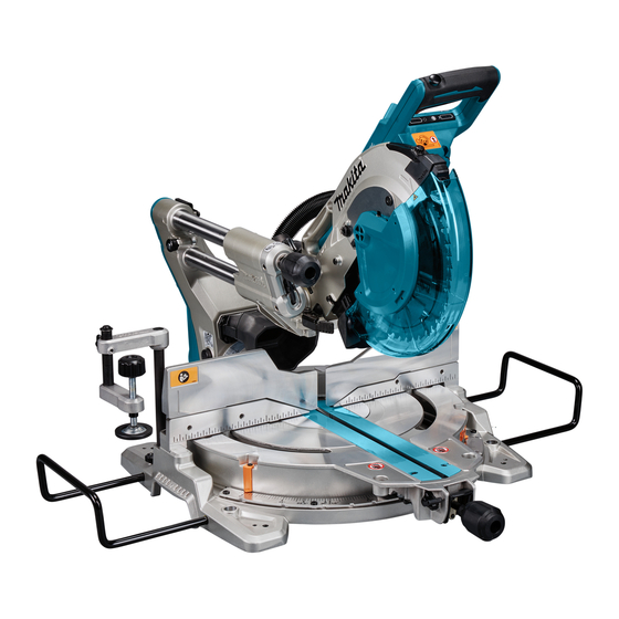
- Page 1 INSTRUCTION MANUAL Cordless Slide Compound Miter Saw DLS110 DLS111 DLS112 Read before use.
- Page 2 SPECIFICATIONS Model: DLS110 DLS111 DLS112 Blade diameter European countries 260 mm Countries other than Europe 255 mm - 260 mm Hole diameter European countries 30 mm Countries other than Europe 25.4 mm Max. kerf thickness of the saw blade 3.2 mm Max.
- Page 3 Read all safety warnings, instruc- tions, illustrations and specifications provided The typical A-weighted noise level determined accord- with this power tool. Failure to follow all instructions listed below may result in electric shock, fire and/or ing to EN62841: serious injury. Model DLS110 ) : 92 dB(A) Sound pressure level (L Save all warnings and instruc- ) : 102 dB (A) Sound power level (L Uncertainty (K) : 3 dB(A) tions for future reference.
- Page 4 Personal Safety Power tool use and care Stay alert, watch what you are doing and use Do not force the power tool. Use the correct common sense when operating a power tool. power tool for your application. The correct power tool will do the job better and safer at the Do not use a power tool while you are tired or under the influence of drugs, alcohol or med- rate for which it was designed.
- Page 5 Do not use a battery pack or tool that is dam- aged or modified. Damaged or modified batteries may exhibit unpredictable behaviour resulting in fire, explosion or risk of injury. Do not expose a battery pack or tool to fire or excessive temperature. Exposure to fire or tem- perature above 130 °C may cause explosion. Follow all charging instructions and do not charge the battery pack or tool outside the temperature range specified in the instruc-...
-
Page 6: Save These Instructions
14. The cut-off piece must not be jammed or pressed Check the blade carefully for cracks or dam- by any means against the spinning saw blade. If age before operation. Replace cracked or dam- confined, i.e. using length stops, the cut-off piece could aged blade immediately. Gum and wood pitch get wedged against the blade and thrown violently. - Page 7 Makita warranty for the Makita tool and 16. Do not remove the wireless unit from the slot charger. while the power is being supplied to the tool.
- Page 8 25. Do not insert any devices other than Makita 20. Do not leave the wireless unit in a place sub- wireless unit into the slot on the tool.
- Page 9 Switch trigger Lock-off button Hole for padlock Lid (for wireless unit) (For DLS111 only) Switch (for laser line) Battery indicator Mode indicator Check button (For DLS111, DLS112 only) Wireless activation Wireless activation lamp Hose Stopper pin button (for dust extraction) (for carriage elevation) 0° adjusting bolt Guide fence...
- Page 10 Bench mounting INSTALLATION When the tool is shipped, the handle is locked in the Installing the grip lowered position by the stopper pin. While lowering the handle slightly, pull the stopper pin and rotate it 90°. Screw the threaded shaft of the grip into the turn base. ► 1 .
- Page 11 Tool / battery protection system FUNCTIONAL The tool is equipped with a tool/battery protection sys- DESCRIPTION tem. This system automatically cuts off power to the motor to extend tool and battery life. The tool will auto- matically stop during operation if the tool or battery is WARNING: Always be sure that the tool is placed under one of the following conditions: switched off and the battery cartridge is removed before adjusting or checking the functions on Overload protection the tool.
- Page 12 Battery indicator status Remaining NOTE: Depending on the conditions of use and the battery ambient temperature, the indication may differ slightly capacity from the actual capacity. Blinking 50% to 100% Automatic speed change function 20% to 50% 0% to 20% Charge the battery Indicating the remaining battery...
- Page 13 Do not remove spring holding blade guard. If guard becomes discolored through age or UV light exposure, contact a Makita service center for a new guard. DO NOT DEFEAT OR REMOVE GUARD. ► 1 . Left bevel cut 2. Straight cut 3. Right bevel cut 4.
- Page 14 Maintaining maximum cutting capacity This tool is factory adjusted to provide the maximum cutting capacity for a 260 mm saw blade. When installing a new blade, always check the lower limit position of the blade and if necessary, adjust it as follows: First, remove the batteries. Turn the stopper lever to engaged position. ► 1 . Top surface of turn base 2. Periphery of blade 3. Guide fence With the batteries removed, rotate the blade by hand ► 1 .
- Page 15 NOTE: If you depress the releasing lever, you can move the turn base without holding down the lock lever. Tighten the grip at your desired position. This miter saw employs positive stop function. You can set 0°, 15°, 22.5°, 31.6°, 45°, and 60° right/left miter angle quickly. To use this function, move the turn base close to your desired positive stop angle while holding down the lock lever. Then release the lock lever and move the turn base forward until the turn base is locked. Adjusting the bevel angle NOTICE: Always remove the upper guide fences...
- Page 16 Match the pointer with your desired angle on the scale by moving the carriage then tighten the knob. ► 1 . Releasing lever This miter saw employs positive stop function. You can set 22.5° and 33.9° angle to both right and left quickly. Set the latch lever in the position as illustrated and tilt the carriage. To change the angle, pull the latch lever and tilt the carriage. ► 1 .
- Page 17 (0) of the switch. ing the lock-off button. A switch in need of repair may result in unintentional operation and serious personal injury. Return tool to a Makita service center for proper repairs BEFORE further usage. ► 1 . Switch for laser Laser line can be shifted to either the left or right side of the saw blade by turning the adjusting screw as follows.
- Page 18 WARNING: Use only the Makita wrench pro- vided to install or remove the blade. Failure to use the wrench may result in overtightening or insufficient A) When you want to obtain the correct size on the left tightening of the hex socket bolt and serious personal injury.
-
Page 19: Removing The Blade
Removing the blade Installing the blade Loosen the hex bolt holding the center cover using the Mount the blade carefully onto the spindle, making hex wrench. Raise the blade guard and center cover. sure that the direction of the arrow on the surface of the blade matches the direction of the arrow on the blade case. - Page 20 When you wish to perform clean cutting operation, con- remove particles adhering to the insides which might nect a Makita vacuum cleaner to the dust nozzle using hamper further collection. a front cuff 24 (optional accessory).
- Page 21 Guide fences WARNING: Before operating the tool, make sure that the upper fence is secured firmly. WARNING: Before bevel-cutting, make sure that no part of the tool, especially the blade, con- tacts the upper and lower fences when fully low- ering and raising the handle in any position and while moving the carriage through its full range of travel.
- Page 22 Horizontal vise Optional accessory WARNING: Always rotate the vise nut clock- wise until the workpiece is properly secured. If the workpiece is not properly secured the material may move during the cutting operation causing possible damage to the blade, causing the material to be thrown and loss of control resulting in serious personal injury.
- Page 23 Press cutting WARNING: Always lock the sliding movement of the carriage when performing a press cutting. Cutting without lock may cause possible kickback which may result in serious personal injury. Workpieces up to 68 mm high and 160 mm wide can be cut in the following manner. ► 1 .
- Page 24 When the cut is completed, switch off the tool and Bevel cut wait until the blade has come to a complete stop before returning the blade to its fully elevated position. WARNING: After setting the blade for a bevel Compound cutting cut, ensure that the carriage and blade will have free travel throughout the entire range of the Compound cutting is the process in which a bevel...
- Page 25 Table (A) – Molding Bevel angle Miter angle position 52/38° 45° type 52/38° 45° type in the type type figure Left Left 30° Right Right inside 33.9° 31.6° 35.3° corner Left Left 31.6° 35.3° outside Right Right corner 31.6° 35.3° Table (B) 1.
- Page 26 Table (A) At left 45° miter angle – Molding Bevel angle Miter angle position 52/38° 45° type 52/38° 45° type in the type type figure Right Right Right Right inside 33.9° 30° 31.6° 35.3° corner Left Left 31.6° 35.3° outside Right Right corner...
- Page 27 Table (C) For a dado type cut, perform as follows: Adjust the lower limit position of the blade using – Molding Miter angle Finished the adjusting screw and the stopper arm to limit the cut- position in piece ting depth of the blade. Refer to "Stopper arm" section the figure described on previously. For inside Right 45° Save the right After adjusting the lower limit position of the blade, corner side of blade cut parallel grooves across the width of the workpiece Left 45°...
- Page 28 Installing the wireless unit WARNING: Stopper pin for carriage elevation is for carrying and storage purposes only and not for any cutting operations. The use of the stopper Place the tool on a flat and stable CAUTION: pin for cutting operations may cause unexpected surface when installing the wireless unit. movement of the saw blade resulting in kickback and serious personal injury.
- Page 29 If the hooks do not catch the wireless unit, close the lid completely and open it slowly again. Tool registration for the vacuum cleaner NOTE: A Makita vacuum cleaner supporting the wireless activation function is required for the tool registration. NOTE: Finish installing the wireless unit to the tool before starting the tool registration.
- Page 30 Push the wireless activation button on the tool NOTE: The wireless activation lamps finish blinking briefly. The wireless activation lamp will blink in blue. in green after 20 seconds elapsed. Finish pressing the wireless activation button on the tool while the wireless activation lamp on the vacuum cleaner is blinking. If the wireless activation lamp does not blink in green, push the wireless activation button briefly and hold it down again.
- Page 31 Description of the wireless activation lamp status ► 1 . Wireless activation lamp The wireless activation lamp shows the status of the wireless activation function. Refer to the table below for the meaning of the lamp status. Status Wireless activation lamp Description Color Duration Blinking The wireless activation of the vacuum cleaner is available. The Standby Blue 2 hours lamp will automatically turn off when no operation is performed for 2 hours.
- Page 32 If the cancellation is performed successfully, the wire- Cancelling tool registration for the less activation lamps will light up in red for 2 seconds vacuum cleaner and start blinking in blue. NOTE: The wireless activation lamps finish blinking Perform the following procedure when cancelling the in red after 20 seconds elapsed. Finish pressing tool registration for the vacuum cleaner.
- Page 33 Troubleshooting for wireless activation function Before asking for repairs, conduct your own inspection first. If you find a problem that is not explained in the manual, do not attempt to dismantle the tool. Instead, ask Makita Authorized Service Centers, always using Makita replace- ment parts for repairs. State of abnormality Probable cause (malfunction) Remedy The wireless activation lamp does The wireless unit is not installed into Install the wireless unit correctly. not light/blink. the tool. The wireless unit is improperly installed into the tool. The terminal of the wireless unit and/or Gently wipe off dust and dirt on the terminal of the the slot is dirty.
-
Page 34: Miter Angle
State of abnormality Probable cause (malfunction) Remedy The vacuum cleaner does not run The wireless unit is not installed into Install the wireless unit correctly. along with the switch operation of the tool. The wireless unit is improperly installed the tool. into the tool. The terminal of the wireless unit and/or Gently wipe off dust and dirt on the terminal of the the slot is dirty. - Page 35 ► 1 . Triangular rule 2. Saw blade 3. Top surface of ► 1 . Triangular rule turn base Bevel angle Check if the side of the blade squares with the turn base surface once again. Loosen the screw on the pointer. 0° bevel angle Align the pointer with 0° position in the bevel angle scale and then tighten the screw. Push the carriage toward the guide fence and lock the sliding movement by the stopper pin.
- Page 36 Beware that impacts to the tool. It may cause the laser line to be misaligned or may cause damage to the laser, shortening its life. NOTICE: Have the tool repaired by a Makita authorized service center for any failure on the laser unit. The movable range of laser line is decided by the range adjustment screws on both sides. Perform following...
- Page 37 Misuse of periodically. an accessory or attachment may result in serious personal injury. If you need any assistance for more details regard- ing these accessories, ask your local Makita Service Center. • Steel & Carbide-tipped saw blades • Vertical vise •...
- Page 40 Jan-Baptist Vinkstraat 2, Makita Europe N.V. 3070 Kortenberg, Belgium 3-11-8, Sumiyoshi-cho, Makita Corporation Anjo, Aichi 446-8502 Japan 885613B222 www.makita.com 20170523...