
Related Manuals for Toshiba AJ65VBTCU-68ADVN


Summary of Contents for Toshiba AJ65VBTCU-68ADVN
- Page 1 Analog-Digital Converter Module Type AJ65VBTCU-68ADVN/ADIN User s Manual Mitsubishi Programmable Controller...
-
Page 3: Safety Precautions
SAFETY PRECAUTIONS (Always read these precautions before using this equipment.) Before using this product, please read this manual and the relevant manuals introduced in this manual carefully and pay full attention to safety to handle the product correctly. The precautions given in this manual are concerned with this product. Refer to the user’s manual of the CPU module to use for a description of the PLC system safety precautions. -
Page 4: Wiring Precautions
[Installation Precautions] CAUTION Use the PLC in the environment that meets the general specifications contained in this Manual. Using the PLC outside the range of the general specifications may result in electric shock, fire or malfunction, or may damage or degrade the module. Securely fix the module to a DIN rail or securely fix it with the CC-Link connector type metal installation fitting. - Page 5 [Starting and Maintenance Precautions] CAUTION Do not touch the pin while the power is on. Doing so may cause malfunction. Be sure to shut off all phases of the external power supply used by the system before cleaning. Not doing so can cause the module to fail or malfunction. Never disassemble or modify the module.
-
Page 6: Revisions
REVISIONS * The manual number is given on the bottom left of the back cover. Print Date * Manual Number Revision Apr., 2003 SH (NA)-080401E-A First Printing Sep., 2004 SH (NA)-080401E-B Addition Section 4.8.3, 4.10.1 to 4.10.3 Correction About Manuals, Section 1.2, 2.3, 3.2, 4.8.2, 4.9.2 Jul., 2005 SH (NA)-080401E-C Correction... - Page 7 INTRODUCTION Thank you for choosing a Mitsubishi MELSEC-A Series General Purpose Programmable Controller. Before using your new PLC, please read this manual thoroughly to gain an understanding of its functions so you can use it properly. CONTENTS SAFETY PRECAUTIONS..........................A- 1 REVISIONS ..............................A- 4 INTRODUCTION............................A- 5 About Manuals ...............................A- 7...
- Page 8 4 SETUP AND PREPARATION BEFORE OPERATION 4- 1 to 4-23 4.1 Pre-Operation Procedure......................... 4- 1 4.2 Precautions When Handling ........................4- 1 4.3 Name of Each Part........................... 4- 3 4.4 Concept of Mode Select Switch Setting (Selection of Remote Device Station Compatible Version)... 4- 6 4.5 Offset/Gain Setting...........................
-
Page 9: About Manuals
About Manuals The following manuals are also related to this product. In necessary, order them by quoting the details in the tables below. Related Manuals Manual Number Manual Name (Model Code) CC-Link System Master/Local Module User's Manual type AJ61BT11/A1SJ61BT11 IB-66721 Describes the system configuration, performance specifications, functions, handling, wiring and (13J872) troubleshooting of the AJ61BT11 and A1SJ61BT11. -
Page 10: About The Generic Terms And Abbreviations
About the Generic Terms and Abbreviations Unless otherwise specified, the following generic terms and abbreviations are used in this manual to describe Type AJ65VBTCU-68ADVN/ADIN analog-digital converter module. Generic Term/Abbreviation Description Generic product name of the product types SWnD5C-GPPW-E, SWnD5C-GPPW-EA GX Developer ,SWnD5C-GPPW-EV and SWnD5C-GPPW-EVA (n in the type indicates 4 or more.) -
Page 11: Product Components
Product components This product consists of the following. Model name Product Name Quantity Type AJ65VBTCU-68ADVN analog-digital converter module AJ65VBTCU-68ADVN Type AJ65VBTCU-68ADVN/ADIN analog-digital converter module user's manual (hardware) Type AJ65VBTCU-68ADIN analog-digital converter module AJ65VBTCU-68ADIN Type AJ65VBTCU-68ADVN/ADIN analog-digital converter module user's manual (hardware) -
Page 12: Cc-Link Compatible Functions
In this manual, the AJ65VBTCU-68ADVN and AJ65VBTCU-68ADIN are generically referred to as the AJ65VBTCU-68ADVN/ADIN. The AJ65VBTCU-68ADVN/ADIN converts the analog signals (voltage or current input) from the PLC's external source to a 16-bit encoded binary data digital value. For the explanation of this product, the conventional AJ65VBTCU-68ADV analog- digital converter module (hereafter abbreviated to the "AJ65VBTCU-68ADV") and... -
Page 13: Features
(4) High resolution of 1/±4000 By changing the input range, you can choose and set the digital value resolution to either 1/4000 or 1/±4000 (Only AJ65VBTCU-68ADVN) to provide high- resolution digital values. (5) Designation of sampling processing or average processing As a conversion method, you can specify sampling processing or average processing per channel. - Page 14 1 OVERVIEW MELSEC-A (8) Replacement of module without stopping CC-Link system The use of the online connectors (for communication, for power supply) allows the module to be changed without the CC-Link system being stopped. Online connector for communication (A6CON-LJ5P) One-touch connector plug for communication (A6CON-L5P) Online connector for power supply/FG...
-
Page 15: Overall Configuration
This chapter describes the system configuration for use of the AJ65VBTCU- 68ADVN/ADIN. 2.1 Overall Configuration The overall configuration for use of the AJ65VBTCU-68ADVN/ADIN is shown below. (1) Remote net ver. 1 mode CC-Link master/local module (master station) CC-Link master/local module (local station) - Page 16 CC-Link master/local module (master station) QJ61BT11N (QJ61BT11(N), A(1S)J61BT11, A(1S)J61QBT11) Ver. 1.10 compatible CC-Link dedicated cable (Remote I/O station) (Intelligent device station) AJ65VBTCU-68ADVN/ADIN (Remote device station) (Remote device station) 1 station occupied RX/RY: 32 points each RWr/RWw: 12 points each Object whose...
-
Page 17: Applicable System
2 SYSTEM CONFIGURATION MELSEC-A 2.2 Applicable System This section explains the applicable system. (1) Applicable master modules The following master modules can be used with the AJ65VBTCU-68ADVN/ADIN. (a) For use in the remote net ver. 1 mode QJ61BT11N QJ61BT11 AJ61BT11... - Page 18 2 SYSTEM CONFIGURATION MELSEC-A POINT For use in the remote net ver. 2 mode or remote net additional mode, the master module of QJ61BT11N and the peripheral software package of GX Developer Version 8.03D or later are required. For more information on the applicable modules (CPU modules, network modules) and applicable software packages, refer to the CC-Link System Master/Local Module User's Manual (Details) QJ61BT11N.
-
Page 19: Parts Sold Separately
2 SYSTEM CONFIGURATION MELSEC-A 2.3 Parts Sold Separately The plugs for AJ65VBTCU-68ADVN/ADIN are sold separately. Please purchase them as necessary. Mitsubishi model Part model name Color of Specifications name (manufacturer) the cover Applicable cable Maximum Applicable cable core size outer diameter... - Page 20 2 SYSTEM CONFIGURATION MELSEC-A REMARK The following table indicates the connectors of this module with which the above plugs/connectors are compatible. Connector of This Module Compatible Optional Parts • One-touch connector plug for communication One-touch connector for • Online connector for communication communication •...
-
Page 21: General Specification
3 SPECIFICATION MELSEC-A 3 SPECIFICATION This chapter provides the specifications of the AJ65VBTCU-68ADVN/ADIN. 3.1 General Specification Table 3.1 indicates the general specifications of the AJ65VBTCU-68ADVN/ADIN. Table 3.1 General specification Item Specification Usage ambient temperature 0 to 55°C Storage ambient temperature -20 to 75°C... -
Page 22: Performance Specification
3 SPECIFICATION MELSEC-A 3.2 Performance Specification Table 3.2 indicates the performance specifications of the AJ65VBTCU-68ADVN/ADIN. Table 3.2 Performance specification Item AJ65VBTCU-68ADVN AJ65VBTCU-68ADIN Protection class IP1XB ⎯ Voltage –10 to 0 to +10V DC (input resistance 1M ) Analog input ⎯... -
Page 23: I/O Conversion Characteristics
3 SPECIFICATION MELSEC-A 3.3 I/O Conversion Characteristics The I/O characteristics is the slope created by connecting the offset and gain values, with a straight line when converting the analog signals (voltage or current input) from an external source of the PLC to digital values. The offset value is an analog input value (voltage or current) at which the digital output value is 0. -
Page 24: Voltage Input Characteristics Of The Aj68Vbtcu-68Advn
3 SPECIFICATION MELSEC-A 3.3.1 Voltage input characteristics of the AJ68VBTCU-68ADVN The voltage input characteristic graph of the AJ65VBTCU-68ADVN is shown below. Analog input parcitcal value 4095 4000 2000 -2000 -4000 -4096 Analog input voltage (V) Analog Input Range Offset Gain... -
Page 25: Current Input Characteristics Of The Aj65Vbtcu-68Adin
3 SPECIFICATION MELSEC-A 3.3.2 Current input characteristics of the AJ65VBTCU-68ADIN The current input characteristic graph of the AJ65VBTCU-68ADIN is shown below. Analog input parcitcal value 4095 4000 2000 -2000 -4000 Analog input current (mA) Analog Input Range Offset Gain Digital Output Maximum Number Setting... -
Page 26: Relationship Between The Offset/Gain Setting And Digital Output Value
4000 (2) Relationship between the maximum resolution and digital output value The maximum resolution of the AJ65VBTCU-68ADVN/ADIN is as indicated in the performance specification. If the following is satisfied from the offset/gain setting, the digital output value does not increases /decreases by one. -
Page 27: Conversion Speed
3.3.5 Conversion speed Conversion speed indicates time from channel changing to A/D conversion completion. Conversion speed per channel of the AJ65VBTCU-68ADVN/ADIN is 1ms. Due to the data link processing time of the CC-Link system, there is a transmission delay until the A/D conversion value is read actually. -
Page 28: Function List
3 SPECIFICATION MELSEC-A 3.4 Function List The AJ65VBTCU-68ADVN/ADIN function list is shown in table 3.3. Table 3.3 AJ65VBTCU-68ADVN/ADIN function list Item Description Refer to Perform A/D conversion of an analog input value one by one and store the result into Section 3.4.1... -
Page 29: Sampling Processing
3×1 = 3 (ms) 3.4.2 Average processing The AJ65VBTCU-68ADVN/ADIN performs A/D conversion to the channel(s) for the average processing specified by the PC CPU for the set number of times or for the set time. The average is then obtained from the total value excluding the maximum and minimum values, and stored in the remote register. -
Page 30: Remote I/O Signals
This section describes the assignment and functions of the remote I/O signals. 3.5.1 Remote I/O signal list Remote inputs (RX) mean the input signals from the AJ65VBTCU-68ADVN/ADIN to the master module, and remote outputs (RY) mean the output signals from the master module to the AJ65VBTCU-68ADVN/ADIN. - Page 31 Table 3.4 indicates the assignment and names of the remote I/O signals for ver. 1 remote device station (ver. 1 compatible slave station) setting. Table 3.4 Remote I/O Signal List for Ver. 1 Remote Device Station (Ver. 1 Compatible Slave Station) Setting Signal direction: AJ65VBTCU-68ADVN/ADIN Master Module Signal direction: Master Module AJ65VBTCU-68ADVN/ADIN...
- Page 32 Table 3.5 indicates the assignment and names of the remote I/O signals for ver. 2 remote device station (ver. 2 compatible slave station) setting. Table 3.5 Remote I/O Signal List for Ver. 2 Remote Device Station (Ver. 2 Compatible Slave Station) Setting Signal direction: AJ65VBTCU-68ADVN/ADIN Master Module Signal direction: Master Module AJ65VBTCU-68ADVN/ADIN...
-
Page 33: Functions Of The Remote I/O Signals
(turned off) by the error reset request flag. PROM write error flag RXnC At occurrence of this error, power on the AJ65VBTCU-68ADVN/ADIN again. If this flag turns on after the power is switched on again, it is a hardware fault. Contact your nearest Mitsubishi representative. - Page 34 Error reset request flag RWrn+8 Error code Error code : Performed by sequence ladder : Performed by AJ65VBTCU-68ADVN/ADIN Turns on when initial data setting is completed after power-on or at termination of the RX(n+1)B Remote READY test mode. (Used for interlocking read/write from/to the master module.)
-
Page 35: Remote Register
3 SPECIFICATION MELSEC-A 3.6 Remote Register The AJ65VBTCU-68ADVN/ADIN has a remote resister for data communication with the master module. The remote register allocation and data structures are described. 3.6.1 Remote register allocation (1) Remote register assignment for ver. 1 remote device station (ver. 1 compatible slave station) setting Table 3.7 indicates the remote register assignment for ver. - Page 36 3 SPECIFICATION MELSEC-A (2) Remote register assignment for ver. 2 remote device station (ver. 2 compatible slave station) setting Table 3.8 indicates the remote register assignment for ver. 2 remote device station (ver. 2 compatible slave station) setting. Table 3.8 Remote Register Assignment for Ver. 2 Remote Device Station (Ver.
- Page 37 (5) AJ65VBTCU-68ADVN/ADIN processing when conversion is enabled/prohibited (a) Average processing initialization The data in the work area stored by the AJ65VBTCU-68ADVN/ADIN system to perform the average processing is initialized. For example, at a channel with the average processing specification at 50...
- Page 38 (1) Set the analog input range per channel. (2) Operation is performed according to the setting made for the leading edges of the initial data setting request flag (RY(n+1)9). (3) The default is as follows. AJ65VBTCU-68ADVN : -10 to +10V AJ65VBTCU-68ADIN : 4 to 20mA RWwm+1 CH.4...
- Page 39 3 SPECIFICATION MELSEC-A 3.6.4 Average processing specification (Address RWwm+3 (1) Selects between sampling processing and average processing selection and when average processing is selected, the processing method is specified. (2) The default is sampling processing on all channels. CH.8 CH.7 CH.6 CH.5 CH.4 CH.3...
- Page 40 If an error occurs (the RUN LED flickers) when data is written to the AJ65VBTCU- 68ADVN/ADIN, the corresponding error code is stored into the remote register (address RWrn+8 ) of the AJ65VBTCU-68ADVN/ADIN. Refer to Section 6.1 for details of the error codes. 3 - 20...
-
Page 41: Pre-Operation Procedure
Start data link. Offset/gain setting (Refer to Section 4.5.) 4.2 Precautions When Handling The precautions when handling the AJ65VBTCU-68ADVN/ADIN are described below: Do not touch the pins while power is on. Doing so can cause a malfunction. CAUTION Ensure that no foreign matter such as chips and wire-offcuts enter the module. - Page 42 (2) As the CC-Link connector type metal installation fitting, use the narrow-width type (width 41)-dedicated fitting. (a) CC-Link connector type metal installation fitting model A6PLT-J65V1 (3) Refer to the Master Module user's manual for specification, and manufacturers of supported cables for the use with AJ65VBTCU-68ADVN/ADIN. 4 - 2 4 - 2...
-
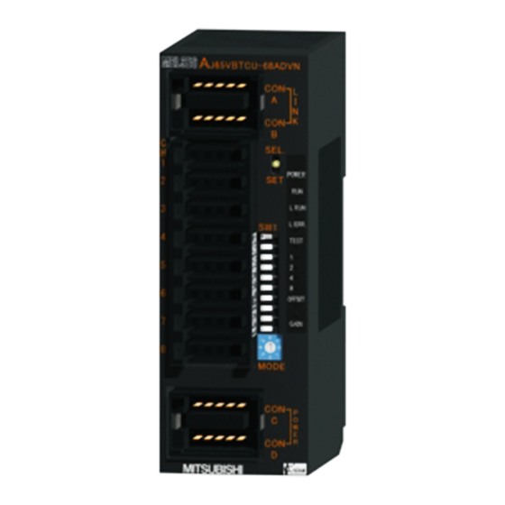
Page 43: Name Of Each Part
4 SETUP AND PREPARATION BEFORE OPERATION MELSEC-A 4.3 Name of Each Part The name of each part in the AJ65VBTCU-68ADVN/ADIN is shown. [Pin layout and signals name] Pin arrangement Pin No. Signal name J65VBTCU-68AD CONA, B CH1 V+/I+ POWER CH1 V-/I-... - Page 44 Used to make offset/gain setting in the test mode. switch The switch to be used for selecting the mode among Ver. remote device station (Ver. -compatible slave station)/Normal mode/Test mode AJ65VBTCU-68ADVN AJ65VBTCU-68ADIN Ver.1 remote 0: Normal mode Ver.1 remote 0: Normal mode...
- Page 45 4 SETUP AND PREPARATION BEFORE OPERATION MELSEC-A Name and Number Description appearance Setting Switches Set Value Transmission Speed Transmission speed setting 156kbps switches 625kbps 2.5Mbps 5.0Mbps 10Mbps Always set the transmission speed within the above range. The switches are all factory-set to OFF. Making any other setting than the above will result in an error flickering the "L ERR."...
-
Page 46: Concept Of Mode Select Switch Setting (Selection Of Remote Device Station Compatible Version)
• Ver. 2 remote device station (Ver. 2 compatible slave station) Set the remote device station version with the "mode select switch" of the AJ65VBTCU-68ADVN/ADIN. Refer to Section 4.3 for details of the mode select switch. In addition, "mode setting" and "station information (station type)" in the network parameters of GX Developer must be set simultaneously. - Page 47 GX Developer network parameters, and the mode select switch setting of the module. Refer to the following table and make selection. : Usable, : Unusable Model Select Switch Setting of Network Parameter Setting AJ65VBTCU-68ADVN/ADIN Master Module Ver. 1 remote device Ver. 2 remote device Station information Mode setting station (Ver.
-
Page 48: Offset/Gain Setting
4 SETUP AND PREPARATION BEFORE OPERATION MELSEC-A 4.5 Offset/Gain Setting When changing the I/O conversion characteristics, follow the procedure below. START Move the SELECT/SET switch to "SET". Release your hand after making sure that the "RUN" LED has turned on . Ver. - Page 49 (4) When making offset/gain setting (in the test mode), set any of the following test modes with the mode select switch. AJ65VBTCU-68ADVN (Ver. 1 remote device station): 1, 2 AJ65VBTCU-68ADVN (Ver. 2 remote device station): 4, 5 AJ65VBTCU-68ADIN (Ver. 1 remote device station): 1 AJ65VBTCU-68ADIN (Ver.
-
Page 50: Station Number Setting
For details, refer to the user's manual of the master module used. 4.7 Facing Direction of the Module Installation The AJ65VBTCU-68ADVN/ADIN module may be installed in any of six orientations using a DIN rail or CC-Link connector type fitting. (There are no restrictions on the facing directions.) -
Page 51: Data Link Cable Wiring
4.8 Data Link Cable Wiring This section explains the wiring of the CC-Link dedicated cable used for connection of the AJ65VBTCU-68ADVN/ADIN and master module. 4.8.1 Instructions for handling the CC-Link dedicated cables Do not handle the CC-Link dedicated cables roughly as described below. Doing so can damage the cables. -
Page 52: Connection Of The Cc-Link Dedicated Cables
4 SETUP AND PREPARATION BEFORE OPERATION MELSEC-A 4.8.2 Connection of the CC-Link dedicated cables Connect the CC-Link dedicated cable between the AJ65VBTCU-68ADVN/ADIN and master module as shown below. One-touch connector plug for communication (A6CON-L5P) Online connector for communication (A6CON-LJ5P) One-touch connector plug... -
Page 53: How To Connect Connectors
4 SETUP AND PREPARATION BEFORE OPERATION MELSEC-A POINT • On this unit, use the Ver. 1.10-compatible CC-Link dedicated cable (FANC- 110SBH, CS-110, FA-CBL200PSBH). You cannot use the Ver. 1.10-compatible CC-Link dedicated cables of other than the above types, CC-Link dedicated cables and CC-Link dedicated, high- performance cables. -
Page 54: Wiring
4 SETUP AND PREPARATION BEFORE OPERATION MELSEC-A 4.9 Wiring This section provides the instructions for wiring the AJ65VBTCU-68ADVN/ADIN and its wiring with external equipment. 4.9.1 Wiring precautions To obtain maximum performance from the functions of AJ65VBTCU-68ADVN/ADIN and improve the system reliability, an external wiring with high durability against noise is required. - Page 55 4 SETUP AND PREPARATION BEFORE OPERATION MELSEC-A (2) AJ65VBTCU-68ADIN Signal souce 0 to 20mA CON1 CH.1 500k CH.1 I+ CH.1 I- 500k 1 Shield CON8 CH.8 500k CH.8 I+ CH.8 I- 500k 1 Shield 1 Use a two-core twisted shield line for the power cable. 2 Indicates the AJ65VBTCU-68ADIN input resistor.
-
Page 56: How To Wire The One-Touch Connector Plug
This section describes the way to wire the one-touch connector plug. Refer to section 2.3 for more information on the types and specifications of the one- touch connector plugs which conform to the AJ65VBTCU-68ADVN/ADIN. 4.10.1 Wiring procedures for the one-touch connector The following are the wiring procedures for the one-touch connector. - Page 57 4 SETUP AND PREPARATION BEFORE OPERATION MELSEC-A (From the previous page) 3) Insert the cable. 4 3 2 1 Lift the end of the plug cover and insert the cable until it almost reaches the plug body (within 1mm from the other end of the plug cover).
- Page 58 4 SETUP AND PREPARATION BEFORE OPERATION MELSEC-A (From the previous page) [Correct example] 7) Check the press-fit condition (viewing from the wiring side). Viewing from the wiring side, check that the plug surface is flush with the plug cover. Do not allow the plug cover to protrude from the plug surface. Note: The condition where the plug cover is tilted or protrudes [Wrong example] from the plug surface as shown in [Wrong example] is an...
-
Page 59: Wiring Procedures For The One-Touch Connector For Communication
4 SETUP AND PREPARATION BEFORE OPERATION MELSEC-A 4.10.2 Wiring procedures for the one-touch connector for communication This section provides the wiring procedures of the one-touch connector for communication. Plug cover Plug body 1) Check the connector. Check that the plug cover is attached to the plug body. Note: Do not push the plug cover into the plug body. - Page 60 4 SETUP AND PREPARATION BEFORE OPERATION MELSEC-A (From the previous page) Pliers 6) Press both ends of the plug cover Latches After pressing the center part of the plug cover, press both ends of the plug cover where latches are located. Verify that the latches engage with the plug body.
-
Page 61: Wiring Procedures For The One-Touch Connector For Power Supply And Fg
4 SETUP AND PREPARATION BEFORE OPERATION MELSEC-A 4.10.3 Wiring procedures for the one-touch connector for power supply and FG The following are the wiring procedures for the one-touch connector used for power supply and FG. Plug body Plug cover 1) Check the connector. Check that the plug cover is attached to the plug body. - Page 62 4 SETUP AND PREPARATION BEFORE OPERATION MELSEC-A (From the previous page) [Correct example] 6) Check the press-fit condition (viewing from the wiring side). Viewing from the wiring side, check that the plug surface is flush with the plug cover. Set the plug cover so that it protrudes 0.2mm or less from the plug surface.
-
Page 63: Maintenance And Inspection
4 SETUP AND PREPARATION BEFORE OPERATION MELSEC-A 4.11 Maintenance and Inspection There are no special inspection items for the AJ65VBTCU-68ADVN/ADIN module, but follow the inspections items describes in the PLC CPU User's Manual so that the system can always be used in the best condition. -
Page 64: Programming Procedure
5 PROGRAMMING MELSEC-A 5 PROGRAMMING The programming procedure, basic read/write programs, and program examples for the AJ765VBTCU-68ADVN/ADIN are described. When utilizing the program example introduced in this chapter for an actual system, fully verify that there are no problems in controllability in the target system. Refer to the user's manual of the master module used for the master module, to Section 3.6 for the remote registers, and to the AnSHCPU/AnACPU/AnUCPU/QCPU (A mode) Programming Manual (Dedicated Instructions) for details of the dedicated... -
Page 65: When Remote Net Ver. 1 Mode Is Used
5.2 When Remote Net Ver. 1 Mode Is Used 5.2.1 Conditions of Program Example The program examples in this section are created under the following conditions. (1) System configuration PLC CPU AJ65VBTCU-68ADVN (Station number 1) Master station (X0 to X1F/Y0 to Y1F) I/O (Input 64 points) - Page 66 5 PROGRAMMING MELSEC-A POINT Some CPU modules may not accept the devices used in the program example in this chapter. For the setting ranges of the devices, refer to the user's manual of the CPU module used. For the A1SCPU, for example, devices X100, Y100 and later are unusable.
-
Page 67: Program Example For Use Of The Qcpu (Q Mode)
5 PROGRAMMING MELSEC-A 5.2.2 Program Example for Use of the QCPU (Q mode) The program examples in this section are created under the following conditions. GX Developer is used to set the network and automatic refresh parameters. Using the remote device station initialization procedure registration function facilitates initial settings. - Page 68 Setting the procedure registration When the initial data processing request flag (RX18) turns on and the remote device station initialization procedure registration (SB0D) is set, the following data are registered to the AJ65VBTCU-68ADVN/ADIN. Procedure Execution Condition Execution A/D conversion enable/prohibit specification: channenls 1, 2: enable (RWw0 :0003 CH.1 to CH.4 input range setting : channel 1: 0 to 5V...
- Page 69 5 PROGRAMMING MELSEC-A (3) Program example Checking of AJ65VBTCU-68ADVN status Reads data link status. AJ65VBTCU-68ADVN data link normal AJ65VBTCU-68ADVN data link abnormal Initialization procedure registration Turns off initialization procedure registration directive. Turns on initialization procedure registration directive. Changing of initial settings ƒ...
-
Page 70: Program Example For Use Of The Qnacpu
5 PROGRAMMING MELSEC-A 5.2.3 Program Example for Use of the QnACPU GX Developer is used to set the network and automatic refresh parameters. (1) Parameter setting (a) Network parameter setting (b) Automatic refresh parameter setting 5 - 7 5 - 7... - Page 71 5 PROGRAMMING MELSEC-A (2) Program example Checking of AJ65VBTCU-68ADVN status Reads data link status. AJ65VBTCU-68ADVN data link normal AJ65VBTCU-68ADVN data link abnormal Initial settings A/D conversion enable/ prohibit specification (RWw0) CH.1 to CH.4 input range setting (RWw1) Average processing specification (RWw3) CH.2 average time,...
-
Page 72: Program Example For Use Of The Acpu/Qcpu (A Mode) (Dedicated Instructions)
A sequence program is used to set the network and automatic refresh parameters. (1) Program example Setting of network parameters using RLPA dedicated instruction Synchronization mode invalid Number of connected modules:1 AJ65VBTCU-68ADVN station information (remote device station, 3 station occupied, station No. 1) Dedicated instruction (RLPA) Starting I/O number of master... - Page 73 Sets W0. Sets 256 points. Dedicated instruction (RRPA) Starting I/O number of master module Parameter storage starting device Checking of AJ65VBTCU-68ADVN status Reads data link status. AJ65VBTCU-68ADVN data link normal AJ65VBTCU-68ADVN data link abnormal Initial settings A/D conversion enable/ prohibit specification (RWw0) CH.1 to CH.4 input...
- Page 74 5 PROGRAMMING MELSEC-A Changing of initial settings Initial setting change A/D conversion enable/ prohibit specification (RWw0) CH.1 to CH.4 input range setting (RWw1) Average processing specification (RWw3) CH.2 average time, number of times setting (RWw5) Turns on initial data setting request flag (RY19).
-
Page 75: Program Example For Use Of The Acpu/Qcpu (A Mode) (From/To Instructions)
Turns off start request signal at abnormal completion of start. Read of remote input signals RX00 to RX1F are read to X400 to X41F Checking of AJ65VBTCU-68ADVN status Reads data link status. AJ65VBTCU-68ADVN data link normal AJ65VBTCU-68ADVN data link abnormal... - Page 76 5 PROGRAMMING MELSEC-A Average processing specification (RWw3) Writes to master station CH.2 average time, number of times setting (RWw5) Writes to master station Turns on initial data processing completion flag (RY18). Turns on initial data setting request flag (RY19). Changing of initial settings Initial setting change A/D conversion enable/ prohibit specification...
-
Page 77: When Remote Net Ver. 2 Mode Is Used
5.3 When Remote Net Ver. 2 Mode Is Used 5.3.1 Conditions of program examples The program examples in this section are created under the following conditions. (1) System configuration AJ65VBTCU-68ADI AJ65VBTCU-68ADVN (Station number 1) (Station number 4) Ver. 1 remote device station Ver. 2 remote device station Q12HCPU (Ver. - Page 78 5 PROGRAMMING MELSEC-A Remote device station Remote device station (Station number 1) (Station number 4) PLC CPU AJ65VBTCU-68ADI AJ65VBTCU-68ADVN For write RWw0 (A/D conversion enable/prohibit W1000 specification) RWw1 (CH. 1 to CH. 4 input range W1001 setting) RWw2 (CH. 5 to CH. 8 input range...
- Page 79 Number of average processing times of times setting (RWw5) of channel 2: 16 times POINT When using the AJ65VBTCU-68ADVN as the ver. 2 remote device station in the normal mode, set the mode select switch to "3". 5 - 16 5 - 16...
-
Page 80: Setting Of Parameters And Initialization Procedure Registration
5 PROGRAMMING MELSEC-A 5.3.2 Setting of parameters and initialization procedure registration The network parameters and automatic refresh parameters are set using GX Developer. Use of the remote device station initialization procedure registration function makes initial setting easy. (1) Parameter setting (a) Network parameter setting (b) Automatic refresh parameter setting 5 - 17... - Page 81 5 PROGRAMMING MELSEC-A (2) Initial setting by remote device station initialization procedure registration function Setting of target station numbers Set the station numbers to which initial setting will be made. Set the target station numbers to "1" and "4". Selection of procedure registration (part 1) Make setting for the AJ65VBTCU-68ADI.
- Page 82 Initial data setting completion flag (RX19) turns ON Initial data setting request flag (RY19) is turned OFF. Setting result (part 2) The following indicates the setting result of the AJ65VBTCU-68ADVN. POINT For the case where the remote device station initialization procedure registration function is not used but a sequence program is used to make setting, refer to the user's manual of the used master module.
-
Page 83: Program Example
5 PROGRAMMING MELSEC-A 5.3.3 Program example Confirmation of AJ65VBTCU-68ADI, AJ65VBTCU-68ADVN status AJ65VBTCU-68ADI AJ65VBTCU-68ADVN Data link normal AJ65VBTCU-68ADI Data link abnormal AJ65VBTCU-68ADVN Data link abnormal Initialization procedure registration Turns OFF the initialization procedure registration command. Turns ON the initialization procedure registration command. - Page 84 (RWw5) Turns ON the initial data setting request flag (RY19). Turns OFF the initial data setting request flag (RY19). AJ65VBTCU-68ADVN Read of digital output values AJ65VBTCU-68ADVN Reads the CH. 1 digital output value (RWr0). Reads the CH. 2 digital output value (RWr1).
-
Page 85: When Remote Net Additional Mode Is Used
5.4 When Remote Net Additional Mode Is Used 5.4.1 Conditions of program examples The program examples in this section are created under the following conditions. (1) System configuration AJ65VBTCU-68ADI AJ65VBTCU-68ADVN (Station number 1) (Station number 4) Ver. 1 remote device station Ver. 2 remote device station Q12HCPU (Ver. - Page 86 5 PROGRAMMING MELSEC-A Remote device station Remote device station (Station number 1) (Station number 4) PLC CPU AJ65VBTCU-68ADI AJ65VBTCU-68ADVN Ver. 1 compatible For write RWw0 (A/D conversion enable/prohibit W100 specification) RWw1 (CH. 1 to CH. 4 input range W101 setting) RWw2 (CH.
- Page 87 Number of average processing times of times setting (RWw5) of channel 2: 16 times POINT When using the AJ65VBTCU-68ADVN as the ver. 2 remote device station in the normal mode, set the mode select switch to "3". 5 - 24 5 - 24...
-
Page 88: Setting Of Parameters And Initialization Procedure Registration
5 PROGRAMMING MELSEC-A 5.4.2 Setting of parameters and initialization procedure registration The network parameters and automatic refresh parameters are set using GX Developer. Use of the remote device station initialization procedure registration function makes initial setting easy. (1) Parameter setting (a) Network parameter setting (b) Automatic refresh parameter setting 5 - 25... - Page 89 5 PROGRAMMING MELSEC-A (2) Initial setting by remote device station initialization procedure registration function Setting of target station numbers Set the station numbers to which initial setting will be made. Set the target station numbers to "1" and "4". Selection of procedure registration (part 1) Make setting for the AJ65VBTCU-68ADI.
- Page 90 Initial data setting completion flag (RX19) turns ON Initial data setting request flag (RY19) is turned OFF. Setting result (part 2) The following indicates the setting result of the AJ65VBTCU-68ADVN. POINT For the case where the remote device station initialization procedure registration function is not used but a sequence program is used to make setting, refer to the user's manual of the used master module.
-
Page 91: Program Example
5 PROGRAMMING MELSEC-A 5.4.3 Program example Confirmation of AJ65VBTCU-68ADI, AJ65VBTCU-68ADVN status AJ65VBTCU-68ADI AJ65VBTCU-68ADVN Data link normal AJ65VBTCU-68ADI Data link abnormal AJ65VBTCU-68ADVN Data link abnormal Initialization procedure registration Turns OFF the initialization procedure registration command. Turns ON the initialization procedure registration command. - Page 92 (RWw5) Turns ON the initial data setting request flag (RY19). Turns OFF the initial data setting request flag (RY19). AJ65VBTCU-68ADVN Read of digital output values AJ65VBTCU-68ADVN Reads the CH. 1 digital output value (RWr0). Reads the CH. 2 digital output value (RWr1).
-
Page 93: Error Code List
6 TROUBLESHOOTING MELSEC-A 6 TROUBLESHOOTING The details of the errors which may occur when using the AJ65VBTCU-68ADVN/ADIN and troubleshooting are described. 6.1 Error Code List If an error occurs (the "RUN" LED of the AJ65VBTCU-68ADVN/ADIN flickers) during write of data from the PLC CPU to the master module, the corresponding error code is stored into the remote register RWrn+8 of the AJ65VBTCU-68ADVN/ADIN. -
Page 94: Using The Led Indications To Check Errors
This section explains how to check errors using the LED indications of the AJ65VBTCU-68ADVN/ADIN. Refer to the PLC CPU and master module user's manual for issues regarding the PLC CPU and master module. (1) When the AJ65VBTCU-68ADVN/ADIN "POWER" LED is off Check item Corrective action Is 24VDC power on? Check the external power supply. - Page 95 (4) When the AJ65VBTCU-68ADVN/ADIN "L RUN" LED is off Communications are broken. For details, refer to troubleshooting in the user's manual of the master module used. (5) When the AJ65VBTCU-68ADVN/ADIN "L ERR." LED flickers at fixed intervals Check item Corrective action Has the station number or transmission speed...
-
Page 96: When The Digital Output Value Cannot Be Read
Check the error area by checking the signal line or any errors? visually or by conductive check. If he AJ65VBTCU-68ADVN/ADIN module digital output value is normal, the effects are being Remove the AJ65VBTCU-68ADVN/ADIN analog received by noise from an external wiring. So check input cable. -
Page 97: Troubleshooting For The Case Where The "Err." Led Of The Master Station Flickers
6 TROUBLESHOOTING MELSEC-A 6.4 Troubleshooting for the Case where the "ERR." LED of the Master Station Flickers The "ERR"LED on the master station is flashing Do the parameter setting and the installed system configuration match properly? Revise the parameter settings or installed system configuration Are the master station link special registers... - Page 98 6 TROUBLESHOOTING MELSEC-A Is the "L RUN" LED lit? Are the station number setting switches properly (not overlapping with other stations)? Set the station number setting switches properly Turn on the power again Is the transmission speed setting correct? Set the correct transmission speed Turn on the power again Is the communication cable wired properlly ?
-
Page 99: Appendix 1 Comparison, Differences And Compatibility Between New And Conventional Models
Models (1) Comparison between AJ65VBTCU-68ADV/ADI and AJ65VBTCU- 68ADVN/ADIN The following table indicates the comparison between the AJ65VBTCU- 68ADV/ADI and AJ65VBTCU-68ADVN/ADIN. Comparison between AJ65VBTCU-68ADV/ADI and AJ65VBTCU-68ADVN/ADIN Item AJ65VBTCU-68ADV/ADI AJ65VBTCU-68ADVN/ADIN • Ver. 1 remote device station (ver. 1 compatible slave station) or Ver. - Page 100 (3) Compatibility between AJ65VBTCU-68ADV/ADI and AJ65VBTCU- 68ADVN/ADIN There is compatibility when the AJ65VBTCU-68ADVN/ADIN is used as the ver. 1 remote device station in the existing system. (Refer to Section 4.4 for details.) When the AJ65VBTCU-68ADV is replaced by the AJ65VBTCU-68ADVN or...
-
Page 101: Appendix 2 External Dimension Diagram
APPENDIX MELSEC-A Appendix 2 External dimension diagram The outline dimension drawing of the AJ65VBTCU-68ADVN/ADIN is shown below. [AJ65VBTCU-68ADVN/ADIN] 31 (1.22)* 67 (2.64) 41 (1.61) 3.5 (0.14) 16.5 (0.65) J65VBTCU-68AD POWER L RUN L ERR TEST OFFSET GAIN MODE * :This section should be 14.5mm (0.57inch) when an online connector is not installed. - Page 102 INDEX A/D conversion completion flag ....3-13 Gain value ............3-3 A/D conversion enable/prohibit specification General specification ........3-1 ............... 3-17 GX Developer Version 8.03D....2-4,4-7 Absolute maximum input......... 3-2 Accuracy............ 3-2,3-6 Analog input............. 3-2 I/O Conversion Characteristics......3-3 Analog input points.......... 3-2 Initial data processing completion flag ..3-14 Applicable master modules......
- Page 103 Program example for use of the ACPU/QCPU (A mode) (FROM/TO instructions)....5-12 Program example for use of the QCPU (Q mode) (when remote net ver. 1 mode is used)..5-4 Program example for use of the QnACPU..5-7 Programming procedure ......... 5-1 Remote device station....
- Page 104 WARRANTY Please confirm the following product warranty details before using this product. 1. Gratis Warranty Term and Gratis Warranty Range If any faults or defects (hereinafter "Failure") found to be the responsibility of Mitsubishi occurs during use of the product within the gratis warranty term, the product shall be repaired at no cost via the sales representative or Mitsubishi Service Company.
- Page 106 Analog-Digital Converter Module Type AJ65VBTCU-68ADVN/ADIN User s Manual AJ65V-68ADN-U-SY-E MODEL MODEL 13JR65 CODE SH(NA)-080401E-D(0704)MEE HEAD OFFICE : TOKYO BUILDING, 2-7-3 MARUNOUCHI, CHIYODA-KU, TOKYO 100-8310, JAPAN NAGOYA WORKS : 1-14 , YADA-MINAMI 5-CHOME , HIGASHI-KU, NAGOYA , JAPAN When exported from Japan, this manual does not require application to the Ministry of Economy, Trade and Industry for service transaction permission.