
Related Manuals for GE D20

Summary of Contents for GE D20
- Page 1 Grid Solutions D20/D200 Technical Overview PRPI-019 Version 3.00 Revision 10 GE Information...
- Page 2 D20/D200 Technical Overview GE Grid Solutions COPYRIGHT NOTICE © 2007-2017, General Electric Canada. All rights reserved. The information contained in this document is subject to change without notice. The software described in this document is supplied under license and may be used or copied only in accordance with the terms of such license.
- Page 3 Purpose ............................1 Who Should Use this Document? ....................2 Additional Documentation ......................2 Product Support ..........................3 GE Grid Solutions Web Site ....................... 3 GE Technical Support Library ....................3 Contact Technical Support ......................3 What’s New.............................4 D20ME II Main Processor ......................4 D20EME (Ethernet/Memory Expansion) ...................
- Page 4 2.4.9 Interposing Relay Panel ....................57 2.4.10 D20C Combination I/O Peripheral ................59 2.4.11 D20AC, AC Analog Input Peripheral ................ 62 2.5 D20/D200 Power Supplies and Chargers ................. 64 2.5.1 D20 Power Supply Specifications ................65 2.5.2 D20 Battery Chargers ....................66 2.6 D20 Modems ........................
- Page 5 5. Frequently Asked Questions ....................85 5.1 What is the performance of the D20 and D200?............... 85 5.2 What is the difference between the D20 and the D200? ........... 85 5.3 Will VME cards work with my non-VME systems? ............85 5.4 What is the I/O capacity of a D20 system? ...............
- Page 6 Figure 21 Demodulated IRIG B Signal ..................35 Figure 22 D20EME (Ethernet/Memory Expansion) ..............36 Figure 23 D20 I/O Peripheral - Compression Termination ............38 Figure 24 D20 I/O Peripheral – DB25 Termination ..............38 Figure 25 D20 I/O Peripheral – Disconnect Termination ............39 Figure 26 D20 I/O Peripheral –...
- Page 7 Figure 42 D.20 Fiber Optic Splitter .................... 73 Figure 43 D.20 Fiber Optic Splitter .................... 74 Figure 44 D200 Redundancy ...................... 76 Figure 45 Single D20/D200 with Loop Redundancy ..............77 Figure 46 Single D20/D200 with Redundant LAN ..............78 Figure 47 Data Display Panel ..................... 79 GE Information PRPI-019-3.00-10...
- Page 8 Table 1 D20/D200 Power Supply Replacements................6 Table 2 D20/D200 Product Comparison..................10 Table 3 D20/D200 Power Supplies..................... 20 Table 4 D20/D200 Main Processor Specifications ..............31 Table 5 D20/D200 Ethernet Media Types .................. 36 Table 6 D20/D200 I/O Peripherals ..................... 37 Table 7 I/O Processing .........................
-
Page 9: About This Document
• What’s New: This section highlights recent additions and enhancements that have been made to the D20/D200 product line. • 1. System Overview: This section provides an overview of the D20/D200 system hardware and software. • 2. Detailed Technical Description: This section provides a detailed description of the D20/D200 hardware, software and operation. -
Page 10: Who Should Use This Document
GE Grid Solutions Who Should Use this Document? This document is a helpful resource for utility customers or GE partners who are purchasing or evaluating a remote terminal unit or substation control system. It is intended for readers who have knowledge of substation automation equipment and applications. -
Page 11: Product Support
Contact Technical Support The GE Grid Solutions Technical Support is open 24 hours a day, seven days a week for you to talk directly to a GE representative. In the U.S. and Canada, call toll-free: 1 800 547 8629... -
Page 12: What's New
Each D20ME II RS-485 port can communicate with up to 32 devices and operate over distances up to 4000 feet, without the use of repeaters (see note below). The D20ME II is backwards compatible with VME and non-VME versions of the D20 chassis, and with the D200 chassis. For more information, see section 2.2, Main Processor. -
Page 13: D20Eme (Ethernet/Memory Expansion)
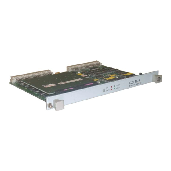
The D20EME is a VME-based module that combines Ethernet support and global memory expansion. Figure 2 D20EME (Ethernet/Memory Expansion) The D20EME allows VME-based D20 and D200 systems to be connected directly to any 10 MB Ethernet-based network. Available configurations of the D20EME module include: • Ethernet only •... -
Page 14: D20 High-Voltage Peripherals
D20 I/O peripherals, but the input and output circuits are conditioned to handle higher voltages. For instance, the high-voltage version of the D20S, the D20 SZ, supports ON thresholds of up to 220 VDC. For more information, see section 2.4, I/O Peripheral. -
Page 15: Multiple Language Support
24 V/3 A Multiple Language Support To meet the needs of our international customers, GE Grid Solutions has added multiple language support to many of our software products that complement the D20/D200, including PowerLink, SGConfig and WESMAINT. These products can be supplied in other languages by request so that end users, such as system operators, can work efficiently in their native language. -
Page 16: System Overview
This section provides an overview of the D20/D200 system hardware and software. More detailed technical information can be found in 2. Detailed Technical Description. The D20/D200 is the heart of GE Grid Solutions’s iSCS (Integrated Substation Control System), as illustrated in Figure 3. -
Page 17: System Architecture
(IEDs, for example), local printers, operator terminals, and SCADA computers. Field data acquired by the D20/D200 is maintained in the system database, where it can be accessed and processed by different application programs. -
Page 18: D20/D200 Product Comparison
The D20 hardware consists of a rack-mountable chassis containing one or more processor boards, power supplies and modems. As shown in Figure 4, the D20 interfaces with substation equipment either through peripheral I/O modules, or directly through RS-232, RS-485, or Ethernet links. -
Page 19: Figure 4 D20 System Architecture
D20/D200 Technical Overview GE Grid Solutions The D20 can support up to: • Two D.20 ports, each supporting up to 31 I/O peripherals, without repeaters, and 120 I/O peripherals, with repeaters • 21 RS-232 or RS-485 ports (7 per processor board) •... -
Page 20: Figure 5 Example D20 Rack Layout
D20/D200 Technical Overview GE Grid Solutions An example of a D20 rack layout is shown in Figure 5. D20 CHASSIS (with 7 COM ports) Optional second 7 COM port panel WESDAC D20A WESTERM D20A DUCT PANEL WESDAC D20S WESTERM D20S... -
Page 21: D200 Substation Automation Platform
1.5 D200 Substation Automation Platform The D200 has the computing power and expandability needed to provide substation automation in larger substations. This is achieved through an innovative design that employs multiple D20 processors, communicating over a VME bus. Figure 6 D200 Substation Automation Platform The D200 has the processing power to monitor and control thousands of I/O points. -
Page 22: Figure 7 D200 System Architecture
D20/D200 Technical Overview GE Grid Solutions D200 hardware is similar in design to the D20 hardware, but it has significantly more physical capacity. Based on a 9-slot VME chassis, the D200, illustrated in Figure 7, can support up to: • 4 D.20 ports, each supporting up to 31 I/O peripherals, without repeaters, and 120 I/O peripherals, with repeaters •... -
Page 23: Figure 8 Example D200 Rack Layout
D20/D200 Technical Overview GE Grid Solutions An example of a D200 rack layout is shown in Figure 8. FAILOVER SUPPLY BLANK PANEL FAILOVER SUPPLY BLANK PANEL L/R SWITCH PANEL DUCT PANEL DUCT PANEL WESDAC D20A WESTERM D20A D200 CCU CHASSIS... -
Page 24: D20/D200 Rtu Hardware
• Media Interface Card For convenience, maintenance ports, test points, indicators and power switches are brought out to the front of the chassis. With VME versions of the D20 and D200 chassis, external connections are provided through rear-mounted termination panels. -
Page 25: Main Processor
D20M+ and D20M++), although no longer available, are still operating at many locations. The current versions of the D20 main processor (D20ME and D20ME II) are described below. For a detailed description of the main processors, see section 2.2, Main Processor. -
Page 26: Figure 11 D20Me Ii Main Processor
RS-485 communications on any of seven serial ports (the eighth is reserved for the RS-232 WESMAINT port). Through each of the RS-485 serial ports, the D20/D200 can communicate point-to-multipoint with large numbers of end devices, out to a distance of 4000 feet. -
Page 27: Ethernet/Memory Expansion (Eme) Kit
The D20 switch-mode power supply, installed in the D20 chassis, provides power to the units that are installed in the chassis, and up to five D20 I/O peripherals depending on the hardware configuration. For larger systems with more than five I/O peripherals, an external power supply is always required. -
Page 28: Modems
Redundant Provides fail-over protection and delivers continuous power to the D20 modules and peripherals. For a listing of available power supplies, refer to section 2.5, D20/D200 Power Supplies and Chargers. 1.6.5 Modems GE Grid Solutions offers a wide range of D20/D200 modems to provide communication between the D20/D200 and SCADA host computers or remote devices, including proprietary WESDAC ®... -
Page 29: Auxiliary Equipment
• D20AC – Up to 15 direct AC inputs and 1 DC analog input For a detailed description, see section 2.4, I/O Peripheral. D20 I/O peripherals are available in standard and high-voltage versions. The high-voltage versions of the peripherals are electrically more robust than the standard versions, and meet a broader range of industry standards. -
Page 30: Firmware
GE Grid Solutions 1.10 Firmware The D20/D200 software is based on a core set of software modules, collectively referred to as the base system. The base system is programmed into the D20/D200 on-board flash memory as firmware. Processing and data acquisition functionality is distributed between the I/O peripheral processors, which have similar but smaller base systems, and the D20 main processor. - Page 31 D20/D200 Technical Overview GE Grid Solutions − Software configuration guides − Maintenance utility user guides • Site-Specific Manual, consisting of: − Bills of Material − Rack layouts − Configuration tables − Termination lists − Cabling schematics − Module layout drawings (complete with wiring and jumper configuration instructions).
-
Page 33: Detailed Technical Description
D20/D200 Technical Overview GE Grid Solutions 2. Detailed Technical Description This section describes the D20/D200 hardware and software design & operation in more detail. 2.1 Mechanical Design and Packaging 2.1.1 General The design of the D20/D200 packaging was driven by the following electric utility requirements: •... -
Page 34: Enclosure
• D20 Chassis (VME) • D200 Chassis (VME) 2.1.3.1 D20 Chassis (non-VME) The D20 chassis is a 3U horizontal slot chassis. Non-VME versions of the D20 provide a single horizontal Eurocard slot, into which the D20ME board is installed: PRPI-019-3.00-10... -
Page 35: Figure 15 D20 Chassis (Non-Vme Version)
The non-VME version of the D20 chassis is equipped with a rear-mounted termination board that provides power connection and serial port access to the D20 system. 2.1.3.2 D20 Chassis (VME) The VME version of the D20 chassis is equipped with five horizontal expansion slots for VME- compatible modules: Figure 16 D20 Chassis (VME version) The VME version of the D20 chassis is equipped with a rear-mounted termination board for power connections and serial ports for one processor board. -
Page 36: Peripheral I/O Module Assembly
2.1.4 Peripheral I/O Module Assembly D20 peripheral I/O modules consist of two separate assemblies - a logic panel and a field termination panel. See Figure 18. The logic panel contains all of the logic circuitry and active components in the peripheral I/O module. -
Page 37: Environmental
If a unit fails, the operator unplugs the failed logic panel and replaces it with a working unit while the power remains on. Once the new unit is installed, the D20/D200 automatically downloads the appropriate operating software and database parameters to the module to make it operational. -
Page 38: Main Processor
GE Grid Solutions 2.2 Main Processor D20ME and D20ME II, which are the main processors for the D20/D200, act as master controllers over D20 peripheral I/O modules, which serve as slaves. The main processors function as data concentrators and central processors of field data. The D20 I/O peripheral modules perform the primary processing of data, which increases the speed and efficiency of the D20, by reducing the workload on the main processor. -
Page 39: D20/D200 Main Processor Specifications
IEDs. The HDLC port handles a bit-oriented D.20 protocol structure for communicating with the D20 I/O peripheral. • VME Bus Interface. The D20ME operates as the VME bus master to allow it to interface to, control and arbitrate the VME bus. -
Page 40: Firmware
2.2.3 Firmware The D20ME contains two types of firmware: BootROM and flash applications. BootROM contains the software needed to start up a D20 and diagnostic applications. Application software consists of a base system that includes the operating system, hardware-dependent software, and applications that are modular and hardware-independent so they can run on multiple platforms (D20, D25 and iBOX, for example). - Page 41 • Efficient real-time responsiveness Boot-Up Code The D20 system initializes from the BootROM. It checks and verifies the contents of the BootROM, then initializes the system hardware and various I/O devices. If it finds any errors or defects in the memory, the system either shuts down to a minimum running state or, in the event of serious defects, shuts down completely.
-
Page 42: Time Synchronization
There are several libraries available for the D20. D.20 Link Subsystem The D.20 Link subsystem is a DCA that polls data from the D20 I/O peripheral modules, and then routes that data to WIN. It also asks the peripherals to perform any output operation requests that it receives from WIN. -
Page 43: Figure 20 D20/D200 Time Synchronization
Figure 20 D20/D200 Time Synchronization To support time synchronization, the D20/D200 must be able to support the device’s protocol, and the device’s protocol must support time synchronization. A sample of the demodulated IRIG B protocol is shown in Figure 21. -
Page 44: Ethernet/Memory Expansion (Eme) Kit
The D20EME is a VME-based module that combines Ethernet support and global memory expansion. If you install multiple D20ME or D20ME II main processors in the D20 or D200 VME chassis, you will need to install a D20EME Ethernet/Memory Expansion module to provide shared memory. -
Page 45: I/O Peripheral Modules
• D20AC direct AC analog input I/O peripheral modules are available with a variety of I/O point count support and termination options. The following is a listing of the various D20 I/O peripherals that are currently available from GE Grid Solutions:... -
Page 46: Termination Types
D20 I/O Peripheral, as illustrated below: Figure 23 D20 I/O Peripheral - Compression Termination • DB25: Field wiring is terminated onto the D20 I/O peripheral through DB25 connectors, as illustrated below: Figure 24 D20 I/O Peripheral – DB25 Termination PRPI-019-3.00-10... -
Page 47: Figure 25 D20 I/O Peripheral – Disconnect Termination
- 0.6 x 3.5 x 100 mm), which then mate with board-mounted headers on the D20 I/O Peripheral. This is illustrated in Figure 25, with the board-mounted header shown on the right, and the cable plug shown on the left. -
Page 48: Hardware
• Serial I/O: Consists of the D.20 communication and maintenance ports. • Power Supply: Accepts an input voltage of 20 to 60 V DC, provided from either the host D20 power supply or an external power source, and supplies a regulated output of +5 V and +/-12 VDC. -
Page 49: Firmware
There are two main types of peripheral I/O software: common code and base-application code. Similar to the D20 main processor software, peripheral software is installed as firmware on the modules. Common code is resident in the peripheral modules, and device-specific base applications are stored in the D20 main processor then downloaded to the peripheral modules at boot-up. - Page 50 Peripheral Communications The resident peripheral communication process functions continuously, requesting and receiving data from the I/O peripherals, then forwarding these over the HDLC link to the D20 main processor. Module-specific applications and configurations are downloaded to the D20 I/O peripherals as required. Communication failures between the D20 main processor and D20 I/O peripherals are logged and reported to the master if required.
-
Page 51: I/O Processing
These functions are initiated by a separate clock source or hardware-driven IRQ rather than by the real-time executive. The base-application code is stored in the EPROM (labeled “pcommon”) on the D20 main processor and downloaded to the peripheral modules, where it is stored in RAM, along with a checksum for verification purposes. -
Page 52: D20S Digital Input Peripheral
Note: D20C peripherals are also able to process digital inputs. Digital input processing on the D20C is the same as that on the D20 S. More information on the D20C is provided in section 2.4.10 , D20C Combination I/O Peripheral. -
Page 53: Figure 29 D20S Digital Input Peripheral Block Diagram
D20/D200 Technical Overview GE Grid Solutions millisecond and placed in a first in - first out (FIFO) buffer for transmission to the D20 main processor. Refer to Figure 29. Time-tagged changes are reported in chronological order. Non-time-tagged changes are placed in a separate FIFO buffer and reported upon request. - Page 54 The results of processing are either buffered COS, SOE or transition counts for accumulator inputs. • Communication Interface, with the D20 main processor, consists of a set of interface- function address tables that are downloaded with the base-application code. The addressed functions are application controls and data transfer functions.
-
Page 55: Table 8 D20S Specifications
D20/D200 Technical Overview GE Grid Solutions 2.4.6.3 D20S Specifications Table 8 D20S Specifications Item Description Processor 8-bit Freescale 68HC11 MPU Clock 2 MHz MPU clock • Memory 32 KB EPROM • 24 KB static RAM • 512 bytes EEPROM Inputs 64 bipolar inputs in 8 groups of 8 •... -
Page 56: D20A Analog Input Peripheral
D20/D200 Technical Overview GE Grid Solutions GE Part Number Description 517-0219 D20SX 64 channel digital input termination board with separable compression blocks. 517-0327 D20SB 64 channel input termination board with barrier strips. 517-0330 D20SDI 24V, 64 channel digital input termination board with DB25 connectors... -
Page 57: Figure 31 D20A Analog Input Peripheral Block Diagram
D20/D200 Technical Overview GE Grid Solutions The analog input section consists of a filter and solid-state multiplexer, a variable-gain amplifier, an integrating voltage-to-frequency converter, a programmable timer, a CPU time register and miscellaneous support circuitry. Figure 31 is a block diagram of the analog input peripheral. - Page 58 (Line B, exaggerated for demonstration purposes). The D20 minimizes this error by a technique called three-point linearity correction. By separately calculating the linearity difference (slope m) of the 0 to +5 V and 0 to -5 V ranges, the software can use a different equation for either positive or negative values.
-
Page 59: Figure 33 Three-Point Linearity Correction
D20/D200 Technical Overview GE Grid Solutions Line C: Y = m X + b Line A: Y = m X + b +16383 Digitized Analog 0000 Line B -16383 Frequency (kHz) Figure 33 Three-point Linearity Correction 2.4.7.2 D20A Analog Input Processing The following analog input processing is carried out by the D20A: •... -
Page 60: Table 10 D20A Specifications
D20/D200 Technical Overview GE Grid Solutions • Communication Interface with D20ME consists of data control and formatting functions that are called by common code using application interface tables. The formatting functions place the requested data into an addressed buffer. • Maintenance Interface implements several maintenance and diagnostic commands. -
Page 61: D20K Control Output Peripheral
The D20K also provides a Local/Remote switch and control output fusing. The Local/Remote switch is a manually operated switch used to disable D20K relay coil power during maintenance. An off-line indication is passed to the D20 main processor, which is available as a pseudo status to the host. - Page 62 D20/D200 Technical Overview GE Grid Solutions 2.4.8.1 Control Output Configurations The D20K can have one of the following control output configurations: • 32 Trip/Close pairs • 24 Trip/Close and 4 Raise/Lower pairs • 16 Trip/Close and 8 Raise/Lower pairs • 8 Trip/Close and 12 Raise/Lower pairs •...
- Page 63 • Simultaneous Digital Output Points: D20/D200 peripherals support the simultaneous control of digital output points, where these output points must be operated at precisely the same time.
-
Page 64: Table 12 D20K Specifications
D20/D200 Technical Overview GE Grid Solutions 2.4.8.5 D20K Specifications Table 12 D20K Specifications Item Description Processor 8-bit Freescale 68HC11 MPU Clock 2 MHz MPU clock • Memory 32 KB EPROM • 24 KB static RAM • 512 bytes EEPROM •... -
Page 65: Interposing Relay Panel
D20/D200 Technical Overview GE Grid Solutions Item Description Maintenance Port 9600 baud, RS-232 Power Requirements 20-60 VDC, 4 W typical at 24 V, 11 W max. at 24 V with all relays energized • Size D20K logic board and D20K relay termination board assembly: 19" x 5.25" x 2.5"... -
Page 66: Figure 35 Interposing Relays
The following D20KI termination board options are currently available: Table 14 D20KI Options GE Part Number Description 517-0146 D20 KI compression termination 517-0430 D20KI1X, separateable compression termination 517-0147 D20KI2, barrier strip termination Each D20KI, equipped with 16 relays, can be configured to supply 16 momentary, 8 trip/close or 8 raise/lower control outputs. -
Page 67: D20C Combination I/O Peripheral
D20 main processor, which is available to the host as a pseudo-status. 2.4.10.2 D20C Specifications For a more complete description on the status, analog and control features of the D20 C, refer to the sections on the D20S, D20A and D20K modules. -
Page 68: Table 16 D20C Specifications
D20/D200 Technical Overview GE Grid Solutions Table 16 D20C Specifications Item Description Processor 8-bit Freescale 68HC11 MPU Clock 3 MHz MPU clock • Memory 24 KB EPROM • 32 KB static RAM • 512 bytes EEPROM Analog Inputs Physical Plug-in daughter board for 16 bipolar, differential inputs Input Adapters Refer to the Index for a list of available input adapters. -
Page 69: Table 17 D20C Options
D20/D200 Technical Overview GE Grid Solutions Control Outputs Physical 8 relays plus two Master Trip/Close relays • Output Configurations 8 T/C pairs • 6 T/C + 1 R/L pairs • 4 T/C + 2 R/L pairs • 2 T/C + 3 R/L pairs •... -
Page 70: D20Ac, Ac Analog Input Peripheral
D20/D200 Technical Overview GE Grid Solutions 2.4.11 D20AC, AC Analog Input Peripheral The D20AC, AC analog input peripheral provides AC analog computing and monitoring. It has the following features and specifications: Table 18 D20AC Features and Specifications Item Description Features Up to 132 analog values and 18 accumulator values. -
Page 71: Table 19 D20Ac Options
D20/D200 Technical Overview GE Grid Solutions Item Description Frequency Response 50/60 Hz filtered, 1300 Hz unfiltered Sample Rate 64 samples per cycle DC Analog Input One DC differential analog input Current Input One of: + 1, + 5, + 10, + 20 mA Input Burden >... -
Page 72: D20/D200 Power Supplies And Chargers
VME cards, modems and D20 peripheral I/O modules, as required. The power supplies are designed to accept standard voltage inputs and meet the power requirements of the D20/D200. These power supply modules mount vertically in the D20/D200 chassis, as shown in Figure 36 and Figure 37. Figure 36 D20 Power Supply PRPI-019-3.00-10... -
Page 73: D20 Power Supply Specifications
D20/D200 Technical Overview GE Grid Solutions Figure 37 D200 Power Supplies 2.5.1 D20 Power Supply Specifications The following table gives details of the standard chassis-mounted, auxiliary and redundant power supplies that are available. Other power supplies are available for specific requirements. Contact GE Grid Solutions for details. -
Page 74: D20 Battery Chargers
510 - 0242 115 VAC + 15% 48 VDC, 2.5 A Rack-mounted 40 – 144 VDC 2.5.2 D20 Battery Chargers GE Grid Solutions offers the following battery chargers: Table 21 D20/D200 Battery Chargers Type Part Number Input Output WESDAC Battery Charger (48V) -
Page 75: D20 Modems
The D20 modems handle communications to the host computer or other intelligent device. Special modem requirements can be addressed through the use of third-party modems, which are connected to the D20/D200 through external RS-232 connections. Refer to Table 22 for details. Table 22 D20/D200 Modems... -
Page 76: Wesdac 202/V.23 Modem Specifications
D20/D200 Technical Overview GE Grid Solutions Modem Specifications • Westermo TD-34 Designed for extreme industrial environments • 2-wire half duplex, 4-wire full duplex • Data rates up to 33.6 kbps • -40 to +70 C, 0 to 95% non-condensing •... -
Page 77: Communications
• Dimensions: 1.75" (4.4 cm) x 19" (48 cm) WESDAC 202/V.23 (vertical) • Vertical mounting in D20/D200 chassis card slot, as shown in Figure 16 and Figure 17. • Screw compression type terminals for 2W/4W connections. Female DB25 connector for RS-232 connection. -
Page 78: D.20 Link
HDLC format with Manchester encoding. Using a D.20 Link, the D20 main processor can support up to 31 D20 I/O peripheral modules in a standard configuration. Repeater/extension modules may be used to expand beyond this limit to a maximum of 120 (D20) or 480 (D200) peripheral I/O modules. -
Page 79: Designing A Distributed D20 Network
D20/D200 Technical Overview GE Grid Solutions 2.8.1 Designing a Distributed D20 Network To set up a distributed D20 peripheral I/O network design, three key factors need to be considered: • Peripheral configuration of each remote location • Approximate distance between peripheral locations •... -
Page 80: D.20 Communication Interface
The D.20 Communication Interface is used as a repeater module for systems requiring more than 31 D20 I/O peripheral modules. It facilitates extension to a maximum of 120 D20 I/O peripherals on a single HDLC communication port. The DCI can also be used to extend the distance range of... -
Page 81: Adapter Modules
HDLC Up to four D.20 Splitter D.20 Links From D20/D200, or from upstream I/O Peripherals Figure 42 D.20 Fiber Optic Splitter The D.20 Fiber Optic Splitter (DFS) provides a 1:4 interface between the RS-485 serial D.20 Link and up to four fiber optic links. The DFS has two RS-485 ports, one input port and one port continuing the D.20 Link daisy chain. -
Page 82: Communication Cables
2.8.5 Communication Cables 2.8.5.1 RS-485 Twisted Wire Shielded cables are required, with one end of the cable shield properly grounded. The D20/D200 and peripherals must be securely and properly grounded within metal enclosures, according to recommended industry practices. RS-485 cabling must meet the following specifications: •... -
Page 83: Power Requirements
D.20 Link is reviewed with respect to cable IR drop. If the IR drop is exceeded, remote D20 peripherals and DCIs will require a local 24/48 V DC power supply. For 125 V systems, employ a WESDAC Power Converter (125 V DC/AC input, 24 V or 48 V DC output) for local operation of D20 peripherals and DCIs. -
Page 84: D20/D200 Redundancy
RS-232 Switch Panel. The position of the RS-232 Switch Panel, set either automatically or manually, determines which D20/D200 is active. On power up, the active D20/D200 initializes to an “Active Polling” state, acquiring data from all substation devices and any local peripheral I/O reporting to it. Controls are executed as directed by the master host system. -
Page 85: D.20 Link Redundancy
I/O peripheral in the chain is connected back to D.20 Port B. Normally, the D20/D200 will communicate with the I/O peripherals alternately through D.20 Link A and D.20 Link B. In this way, the D20/D200 is able to regularly confirm the integrity of both GE Information... -
Page 86: Auxiliary Equipment
In the case of Failure Scenario 1, the D20/D200 will still be able to communicate with the I/O peripherals through D.20 Link B. In the case of Failure Scenario 2, the D20/D200 will communicate with some peripherals through D.20 Link A, and others through D.20 Link B. -
Page 87: Data Display Panel
The Data Display Panel provides an economical means of displaying up to 150 digital and 150 analog input points from a D20/D200. Any data point available in the D20/D200 database can be viewed from a single data display panel, and all information displayed can be scaled to engineering units for easy interpretation. -
Page 88: Configuration And Maintenance Software
IEC 61131-3 standard. 3.3 WESMAINT WESMAINT is a maintenance facility that resides on the D20 and D200. It uses a series of menus and screens displayed on a PC or VT100 terminal to create a simple interface. WESMAINT presets a window through which field technicians and programmers can look directly into the equipment to view collected data and system status and, for some applications, make changes to the configuration. -
Page 89: Promaint
This monitor facility is intended for advanced users to interpret commands from the maintenance port, such as storing data to memory. It can also execute various application-dependent commands once an application program has been downloaded from the D20/D200. 3.5 68K Monitor The 68K Monitor functions are primarily debugging tools that users can access via a PC or a VT100 terminal with a keyboard. -
Page 90: Application Software
D20/D200 Technical Overview GE Grid Solutions 4. Application Software The D20/D200 can be equipped with a wide range of substation automation and enhanced SCADA applications, some of which are summarized below: 4.1 User Programmable Logic Calculator DTA Soft logic utility to perform mathematical and logical operations... -
Page 91: Communication Services Applications
Toggle a status point every time any data in a configured group changes Alarm Prioritization DTA An alarm filter designed to manage the 3 level alarms reported by GE’s DART pole-top/pad-mount distribution RTU Analog Averaging DTA Average analogs at regular intervals Analog Alarm DTA... -
Page 92: Data Conversion Applications
D20/D200 Technical Overview GE Grid Solutions 4.7 Data Conversion Applications Digital-Analog Value Conversion Convert digital input groups to analog data using binary, BCD, or gray code encoding Digital Input to Counter DTA Count the number of SOE or COS transitions on status points... -
Page 93: Frequently Asked Questions
5.2 What is the difference between the D20 and the D200? The D200, which uses the same hardware modules as those used in the D20, has a much higher capacity than the D20. The D200’s larger chassis can support up to seven vertically mounted D20ME II processors, which, in turn, are each capable of supporting two D.20 and seven RS-... -
Page 94: What Is The I/O Capacity Of A D20 System
Equipped with a D20ME II Main Processor, the D20/D200 can support RS-485 communications on all seven communications ports. End devices can be supported at distances up to 4000 feet, and the D20/200 can support up to 32 devices on each communication port, without the need for external converters. -
Page 95: A. Specifications And Supported Standards
D20/D200 Technical Overview GE Grid Solutions A. Specifications and Supported Standards Standard Description D20/D200 with standard D20/D200 with high- D20A, D20S, D20K, voltage peripherals: D20C D20AHV, D20SHV, D20KHV, D20CHV IEC 60068-2-1 Cold C / 96 hr D20: -20 C /96 hr... - Page 96 D20/D200 Technical Overview GE Grid Solutions Standard Description D20/D200 with standard D20/D200 with high- D20A, D20S, D20K, D20C voltage peripherals: D20AHV, D20SHV, D20KHV, D20CHV EN 61000-4-3 Immunity to Radiated Level 3: 10 V/m Level 3: 10 V/m Emissions, 80 - 1000 MHz...
- Page 97 D20/D200 Technical Overview GE Grid Solutions Standard Description D20/D200 with standard D20/D200 with high- D20A, D20S, D20K, voltage peripherals: D20C D20AHV, D20SHV, D20KHV, D20CHV IEEE C37.1-1994 IEEE Standard Definition, Comply Comply Specification and Analysis of System used for Supervisory Control, Data Acquisition,...
-
Page 98: B. Supported Host Protocols
D20/D200 Technical Overview GE Grid Solutions B. Supported Host Protocols The following list is a sampling of the host protocols supported by the D20/D200. GE Grid Solutions is continually adding to this list. Please contact GE Grid Solutions for the latest developments. -
Page 99: C. Supported Ied Protocols
SYPROTEC HYDRAN • INCOM • UCA™ 2.0 • INDACTIC 33 • VANCOM • JEM 2 • LEEDEX DTMF GE Grid Solutions is continually adding to the supported protocol list. Please contact GE Grid Solutions for the latest developments. GE Information PRPI-019-3.00-10... -
Page 100: D. Power Consumption – D20 Modules
D20/D200 Technical Overview GE Grid Solutions D. Power Consumption – D20 Modules Power Consumption (Typical Watts) Module D20ME 4.00 D20S 3.00 D20A 7.00 D20K 4.00 D20K O/B Relay 0.288 D20C 5.00 D20C A/I 1.50 D20C I/O 1.50 Rack Modem 1.44 Universal Protocol Converter 0.680... -
Page 101: E. D20/D200 Main Processor Compatibility
D20/D200 Technical Overview GE Grid Solutions E. D20/D200 Main Processor Compatibility Compatibility of the different versions of D20/D200 main processors and chassis is summarized in below: D20/D200 Chassis Type Board Combinations D20 Non-VME D20 VME D200 VME (All in the same chassis) -
Page 102: F. D.20 Link Installation
Fiber Optic Cable • At the start of the fiber optic cable (D20 end), the following items are required: − D20 fiber optic transceiver, either a 1:1 (DCI) or a 1:4 (DFS), depending on the number of peripheral locations − Glass (GFO) or plastic (PFO) fiber optic adaptors, as required •... - Page 103 Total Power Total Number of units of type ‘x’ Power Consumption of X module (see D. Power Consumption – D20 Modules), where X = M, S, A, K, R, C, C A/I, C I/O, COM, UPC, SP. Constant Current Peripheral Supply Voltage (24, 48, 130 V) Voltage drop/foot Resistive Cable Loss:(#20 AWG [0.812mm] = 0.010 ohms/ft, #22 AWG [0.644mm] = 0.016...
- Page 104 D20/D200 Technical Overview GE Grid Solutions Example: Assume you are installing three D20A and two D20S modules on an RS-485 D.20 Link using wire gauge #22 and a peripheral supply of 48 V. Calculate the maximum distance of the D.20 Link as follows: •...
- Page 105 ........56 Ethernet support ......19, 36 D20 ME ........18, 30 firmware .......... 32 Fiber Optic Interfaces ......79 D20 ME II ......... 4, 18, 30 Frequently Asked Questions ....85 firmware .......... 32 D20 S ..........44 Host Protocols specifications ........
- Page 106 D20/D200 Technical Overview GE Grid Solutions I/O Peripherals RS-485 support ..... 69, 74, 94 common code ......... 41 hardware ......... 40 Software application ......1, 8, 82 supported protocols ......91 maintenance utilities ..1, 8, 22, 80 Interposing Relays......57 Splitters ..........
- Page 107 Jul 21, 2011 Updated Technical Support and Customer Service contact information. Oct 7, 2013 Correction made; The D20 can support up to 21 RS-232 or RS-485 ports (7 per processor board). Oct 15, 2013 Correction made to Table 2: Maximum Serial Ports...