Table of Contents
Operating Instructions
(covering the operations with 600T and 600T EN Pressure Transmitter - Rev. up to 5.3, 652/653S Temperature
- Rev. 5.1, Deltapi K Smart Pressure Transmitter - Rev. up to 5.5, KST Temperature - Rev. up to 5.1, Generic HART
device - HART 5 Revision)
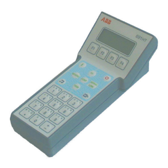
Hand Held Communicator
Model 691HT
INTRINSIC SAFETY VERSION
(Release Firmware 1, Release Software 1.0)
- 1 -
Table of Contents

Related Manuals for ABB 691HT

Summary of Contents for ABB 691HT
-
Page 1: Operating Instructions
Hand Held Communicator Operating Instructions Model 691HT INTRINSIC SAFETY VERSION (Release Firmware 1, Release Software 1.0) (covering the operations with 600T and 600T EN Pressure Transmitter - Rev. up to 5.3, 652/653S Temperature - Rev. 5.1, Deltapi K Smart Pressure Transmitter - Rev. up to 5.5, KST Temperature - Rev. up to 5.1, Generic HART... - Page 2 St Neots, U.K. – Cert. No. Q5907 liquid analysis and environmental applications. Stonehouse, U.K. – Cert. No. FM 21106 As a part of ABB, a world leader in process automation technology, we offer customers application expertise, service and support worldwide. UNI EN 29001 (ISO 9001) We are committed to teamwork, high quality manufacturing, advanced technology and unrivalled service and support.
-
Page 3: Table Of Contents
32 transmitter configurations. GENERAL OPERATIONS ..........8 It can also be used as a Modem between the Personal GETTING STARTED WITH 691HT HAND Computer and the transmitter. TERMINAL ..............9 The Communicator employs a four line by twenty dot- PASSWORD PROCEDURE ........ -
Page 4: Communication Protocol
COMMUNICATION PROTOCOL The communication between the Hand Held Communi- The Data Link Layer is also responsible for the cator and the field devices, like Smart Transmitters, is communication between the field devices and the based on HART protocol, that permits simultaneous configurators, either the Hand Held Communicator, a transmission of the industry-standard 4 to 20 mA analog Secondary Master, or the P.C. -
Page 5: Communicator Applications
The Software that is going to be adopted will be for communication purpose. probably the SMART VISION! Please refer also to the Operating Instructions of the Smart ABB pressure and Control Room Field temperature transmitters for the general and specific Power informations on this products. - Page 6 Communicator. configuration functions left to the P.C.Configurator. STILO OR RECHARGEABLE BATTERY PACK DISPLAY KEYBOARD MICROCONTROLLER to the P.C. MODEM FLASH EEPROM NON-VOLATILE EEPROM RS 232 any point in the loop 691HT Functional Block Diagram - 6 -...
-
Page 7: Keyboard And Display
The display is a 4 line by 20 characters liquid cristal display mounted at an angle to the face of the Commu- 691HT nicator to increase readability. The first two lines of the display are dedicated to data or messages for the user. -
Page 8: General Operations
TRANSMITTER TERMINOLOGY GENERAL OPERATIONS Battery Charging The Communicator primary use is the commissioning There are four nickel-cadmium rechargeable batteries: and the servicing of Smart transmitters. The commis- the expected working time of the Communicator with sioning includes all the operation of functional testing of the transmitter and check of the transmitter configura- the battery full charged is about 10 hours. -
Page 9: Getting Started With 691Ht Hand Terminal
Rev. 1 The ON key must be kept pressed for one second. The first display at side Software Rev. 1.0 appears for some seconds, giving indications on the 691HT revisions and Language: ENGLISH language. After some seconds the Main Menu appears on the screen giving the... -
Page 10: Password Procedure
Note - If you have unlackely forgotten the Password, please contact your [ _ _ _ _ _ _ ] nearest ABB Instrumentation Service Center. CL R E N T R If the password is already disabled or some mistake is made inputting the password, one of the following messages will be displayed: "... -
Page 11: Direct Connection
DIRECT CONNECTION Supposing that a direct connection to the transmitter has been done, MAIN MENU press the function key F1, corresponding to the label "direct", to establish the communication with the transmitter. In the top right angle of the display PASS will appear a symbol, like a T, signalling that the communication is on CAST DIR... -
Page 12: Use Of The Green Keys - Pv Process Value
USE OF THE GREEN KEYS - PV - PROCESS VALUE For 600T, 600T EN and Deltapi K Pressure Transmitters The green key PV ( Process Value ) allows the user to monitor the process P V : 1 2 3 4 . 5 6 m b a r value and the current output of the transmitter. -
Page 13: Use Of The Green Keys - Review
USE OF THE GREEN KEYS - REVIEW The dedicated function key REVIEW allows the user to view the transmitters R E V I E W configuration data. The information contained under Tx Info varies slightly depending on transmitter type. See below the relevant information for 600T and 600T EN Pressure and for 652/653S Temperature transmitters. - Page 14 UP/DOWN SCALE : the value to which the output is PV BIAS VALUE : Value that can be applied to the forced when a major fault occurs. primary variable for scaling. It is stated in the same unit of the primary variable. POLY COEFF.
- Page 15 Here follows the information for Deltapi K Pressure and KST Temperature under Review green key. USE OF THE GREEN KEYS - REVIEW R E V I E W Using the green dedicated function key REVIEW allows the user to view OUT T X MATE N E X T...
- Page 16 Information displayed under MATERIAL BROKEN SENSOR DRIVE : Output driven >20 mA or ( for Deltapi K pressure type only ) <4 mA if the sensor or the sensor connection breaks. FLANGE TYPE : The flange type CAL. CERTIFICATE : Provided or not. FLANGE MATERIAL : The flange material PUSH BUTTONS : Installed or not installed.
-
Page 17: Use Of The Green Keys - Conf Keys
USE OF THE GREEN KEY - CONF KEY Transmitter parameters which are user configurable may be changed by the use of the Configuration Menu accessible via the CONFiguration dedicated function key. These items are organized into Submenus, as follows: For generic HART Transmitter of other manufacturers Change I/O Parameters: Tx Information (XMTR INFO) General Configuration... - Page 18 Use of the Green Key - Access to the CONF procedure I n p u t n u m e r i c p a s s w o r d : The access to the CONF procedure, as well as the TRIM and the ( .
- Page 19 CONF - Change I/O - SENSOR TYPE option ( KST Temp. Transm.) Unlike the pressure transmitter where the sensor is part of the instrument, CONFIGURATION the temperature transmitter can be supplied either complete with his sensor ( thermocouple or RTD ) or without it. It can then be necessary to CHNG XMTR DBASE...
- Page 20 CONF - Change I/O - SENSOR TYPE option ( 652/653 S Temperature transmitter) Unlike the pressure transmitter where the sensor is part of the instrument, the temperature transmitter can be supplied either complete with his sensor ( thermocouple or RTD ) or without it. It can then be necessary to CONFIGURATION configure the transmitter accordingly to the type of sensor and of measurement, single or differential, that will be used.
- Page 21 CONF - Change I / O - UNITS option Using the F1 key to select the procedure CHaNGe I/O the following CONFIGURATION display will appear showing the current units used for defining the operating range of the transmitter, i.e. the LRV and the URV. CHNG XMTR DBASE...
- Page 22 CONF - Change I/O - RANGING option CONFIGURATION The operation of Ranging on the Smart Transmitters differs substantially CHNG XMTR DBASE from the same operation performed in the conventional analog transmitters. I / O I NFO CONF The linearity compensation of the Smart Transmitter allows to select any value of the LRV and URV within the LRL and URL ( lower and upper range limits ) with the unique limitation of the minimum span.
- Page 23 CONF - Change I/O - DAMPING option D A M P I N G : secs From the Configuration main menu press the F1 ( CHNG-I/O ) and then N E X T L A S T CHNG F1 ( NEXT-OPTN ) until the following display is present. O P T N O P T N Pressing F3 a warning message will be displayed: "WARNING - Control loop should be in manual"...
- Page 24 CONF - Change I/O - ROOT XFER FUNCTION option (600T and Deltapi K Pressure Transmitter) ROOT XFER FUNCTION : When the Square Root option is active and SQR (x) selected, two output Undefined modes are available in the 600T transmitters: N E X T L A S T CHNG O P T N O P T N...
- Page 25 CONF - Change I/O - POLY COEFFICIENTS option (600T and 600T EN Pressure Transmitter) The Polynomial function, applied to the input (x) of the trasmitter expressed PO LY C O E F F I C I E N T S in % of the span, is in the following form: N E X T L A S T CHNG...
- Page 26 CONF - Change I/O - DOUBLE POLYNOMIAL COEFFICIENTS option DOUBLE POLY COEFFS (600T EN Pressure Transmitter only) NEXT LAST CHNG The double polynomial function is expressed with the following: OPTN OPTN Out < FIRST POLY LIMIT then Out = B0 + B1 (x) + B2 (x WARNING - control loop else should be in manual...
- Page 27 CONF - General Configuration - UP/DOWN SCALE SETTING CONFIGURATION (Deltapi K Pressure only) CHNG XMTR DBASE From the Configuration main menu press the F3 Key (GEN-CONF) and I / O I NFO CONF then F2 Key (UP/DOWN SCALE). The current selection appears closed within square brackets: using F1 or CONFIG / GENERAL F2 you can select, in turn, up or down.
- Page 28 CONF - Change I/O - Short / Off Values option S H O R T V A L : 2 3 . 0 0 0 (652/653 S Temperature transmitter) O F F V A L U E : 2 3 . 0 0 0 N E X T L A S T C H N G...
- Page 29 For 600T and 600T EN Transmitters: CONFIG / GENERAL For the 600T transmitters the General Configuration menu allows two POLL further selection: Local Keys Control and LCD Display Mode: the ADDR KEYS D I SP relevant display are shown aside. LOCA L KEYS CONTROL The Local Keys Control allows to enable or disable the zero and span [ E n a b l e...
- Page 30 Starting from the Database Main Menu, pressing F3 ( SEND CONF ) the warning message is displayed and the following display appears. Pressing C h o o s e C o n f. t o s e n d F4 to PROCEED, appears the next display showing the list of the S e l e c t T A G configurations present in the Communicator.
-
Page 31: Use Of The Green Keys - Trim Keys
USE OF THE GREEN KEY - TRIM KEY Transmitter parameters which can be calibrated or operations aiding in instrument checkout may be accessed by the use of the Trimming and Setup Menu accessible via the TRIM dedicated function key. The access to this operation is protected by a password, as already explained for CONF dedicated Function Key. - Page 32 Using the TRIM key, when the display with the message " SELECT For Deltapi K Pressure or KST GREEN KEY" is present, the following display will appear: Temperature transmitters Pressing the F4 key ( RERANGING), a warning message is displayed : T R I M M I NG A N D S E T U P "...
- Page 33 Use of the Green Keys - TRIM - 4 to 20 mA Trimming The scope of this operation is to adjust the digital to exercise the output to a full 21 mA, thereby ensuring that analog converter to cover exactly the range 4 to 20 mA. the power supply is capable of providing the necessary This operation requires that a high accuracy digital current.
- Page 34 When the procedure has been completed the screen shows for some R e t u r n i n g X m t r to seconds the display aside. This notice will be followed by the message: o r i g i n a l o u t p u t "WARNING - Loop may be returned to auto"...
- Page 35 Use of the Green Keys - TRIM - Loop Test Option T R I M M I NG A N D S E T U P The scope of this procedure is to test the transmitter output at fixed values, 4 or 20 mA, or at a value selected by the user, and so to test the SNSR 4 - 20 LOOP...
- Page 36 Use of the Green Keys - TRIM - Sensor Trimming option ( for 600T and 600T EN pressure transmitter only ) The scope of the Sensor Trimming operations is to the digital reading with the corresponding analog out- correct the characterisation parameters stored in the put value.
- Page 37 Use of the Green Keys - TRIM - Sensor Trimming - FULL TRIM ( for 600T, 600T EN and Deltapi K pressure transmitter ) CAUTION : remember that this procedure must be done by applying T R I M M I NG A N D S E T U P input pressure, expecially when the choosen span is unfortunately small (<5% of URL).
- Page 38 Use of the Green Keys - TRIM - Sensor Trimming - ZERO TRIM ( for 600T, 600T EN and Deltapi K Pressure Transmitter) S E N S O R T R I M , S E L E CT T Y P E Starting from the main display press the F1 key ( SNSR TRIM ) : the FULL ZERO...
- Page 39 Use of the Green Keys - TRIM - Sensor Trimming - STATIC TRIM S E N S O R T R I M , S E L E CT (for 600T, 600T EN and Deltapi K Pressure Transmitter ) T Y P E Using this procedure it is possible to trim the value of the static pressure used F U L L Z E R O S TAT F A C T...
- Page 40 Use of the Green Keys - TRIM - Calibration - PV Scale Option (600T EN Pressure transmitter only) The scope of this procedure is to allow the user to set the transmitter for TRIMMING AND SETUP reading a specified value of PV, that is to apply a scaling to the PV reading.
- Page 41 While the first one recalculates the LRV and URV maintaining the original LRV : - 200 SPAN, the O/P HIGH recalculates the URV so the SPAN can be URV : + 200 changed. OP : [ 50 When F1 (O/P LOW) is pressed the existing LRV and URV are displayed, <...
- Page 42 Use of the Green Keys - TRIM - Sensor Trimming - S N S R T R I M - ( for KST temperature transmitters ) T R I M M I NG A N D S E T U P Starting from the top display press the F1 key ( SNSR TRIM ) a warning SNSR 4 - 20...
-
Page 43: Use Of The Green Keys - Serial Link
NOTE : Do not introduce change, on the value read, of more that 5% Lo V a l = 0 of the URL at once. If this limit is exceeded a message will be H i V a l = 1 4 . 0 0 0 displayed ( see the relevant section of this manual ). -
Page 44: Hart Response Messages
HART RESPONSE MESSAGES ERROR AND WARNING MESSAGES PARITY ERROR The connected transmitter signals a communication Four types of error and warning messages are generated error: parity not OK ( see Checksum error ) and displayed by the Hand Held Communicator: - communication errors TRANSMITTER DIAGNOSTIC MESSAGES - transmitter diagnostic messages... - Page 45 For 652/653 S temperature transmitter ELECTRONICS TEMP OUT OF LIM (pressure Txs) The temperature of the electronics appears outside of the ADC ERROR specification limits: check in field and, if true, provide INCONGRUENT MEASUREMENT adequate protection to prevent excess temperature of the XOR ERROR transmitter's topwork due to radiation, freezing, etc.
- Page 46 Applied Process too High COMMAND 48: READ ADDITIONAL TRANSMIT- 10 Applied Process too Low TER STATUS the applied pressure exceed the Range limits Command-Specific Response Codes 14 New Lower Range Value shift the Upper Range Value over the Sensor Limit Warning: Update In Progress COMMAND ENTER/EXIT FIXED CURRENT...
- Page 47 COMMAND 135: WRITE POLYNOMIAL COEFFI- COMMAND 142 : WRITE LIMIT FOR DOUBLE POLY CIENTS Command-Specific Response Codes Command-Specific Response Codes Passed Parameter too High Too few bytes received Passed Parameter too Low the number of bytes received is less than Too few bytes received expected the number of bytes received is less than...
- Page 48 In Write Protect Mode In Write Protect Mode the transmitter is in write protect mode the transmitter is in write protect mode CJC too low Shorted sensor value too high Input value for CJC is lower than expected the value defined for shorted sensor is too high 10 RTD multiplication factor too high 10 Shorted sensor value too low Multiplication factor in input is too high...
- Page 49 COMMAND 135: WRITE CALIBRATION LOCATION DATA BASE OPERATIONS MESSAGES Command-Specific Response Code NO TAGS IN DATABASE In Write Protect Mode No configurations stored in the Communicator Databa- The Write protect link on the transmitter is "on" se memory. 12 Invalid Calibration Location code 14 Warning: Default values set for User calibration TAG IS NOT IN HT This message is made the first time the user...
-
Page 50: Appendix "A1
APPENDIX "A1" List of the allowed Sensor Types and relevant Units List of the allowed Measurement type for 652/653 S Temperature transmitter for 652/653 S Temperature transmitter TC /(v)oltage (d)ifferential CJC (int)ernal Sensor Type Measuring Units Ohms Ohms TC /(v)oltage (d)ifferential CJC (ext)ernal Pt100 Pt 100... -
Page 51: Appendix "C
APPENDIX "C" OPERATIONS GUIDE (For 600T and 600T EN pressure transmitter) PV + OUTPUT CURRENT STAT (Here below in bold are indicated the additions for PRESS 600T EN Pressure Transmitters; Root transfer func. remains only for 600T Pressure transmitters.) SENS TEMP Tx type, Manufacturer, Tag, Long Tag, Descriptor, Message, Date, Device Nr., Max work Press., Max... - Page 52 OPERATIONS GUIDE (For 652/653 S temperature transmitter) PV + OUTPUT CURRENT TEMPERA TURE SENSOR 1 - 2 Tx type, Manufacturer, Tag, Descriptor, Message, Date, Device Nr. Units, Range, Damping, Min. Span, Sensor Limits REVIEW Sensor Type, Measurement Type, INFO CJC Temperature, Meter option, Multiplication Factor Max.
- Page 53 OPERATIONS GUIDE (For DPK pressure transmitter) PV + OUTPUT CURRENT STAT PRESS SENS TEMP OUTPUT Units, Range, Damping, Output function, INFO Min. Span, Sensor Limits,Up/Down Scale, Tx type, Manufacturer, Tag, Descriptor, Message, Date, Device Nr., Max work Press., INFO Max Sensor Temp., Min Sensor Temp. REVIEW Flange type and Material, O-rings, Vents, Remote MATERIAL...
- Page 54 OPERATIONS GUIDE (For KST temperature transmitter) PV + OUTPUT CURRENT TEMPERA TURE SENSOR 1 - 2 OUTPUT Units, Range, Damping, Min. Span, Sensor Limits INFO Tx type, Manufacturer, Tag, Descriptor, INFO Message, Date, Device Nr., Meter Option REVIEW REVISION Hardware Rev., Software INFO Rev., UCD, TSD DIRECT...
- Page 55 OPERATIONS GUIDE (For generic Hart transmitter) PV + OUTPUT CURRENT SEC. VARIABLE TERT. VARIABLE FOURTH VARIABLE Tag, Descriptor, Message, Date, Device Nr., REVIEW Units, Range, Damping, Output function, INFO Min. Span, Sensor Limits, Final Ass. nr, Sensor S/N, DIRECT Hardware Rev., Software Rev., UCD, TSD CHANGE BROAD...
-
Page 56: Appendix "D
APPENDIX "D" List of data and parameters saved in the 691HT memory for a Generic HART Transmitter, for Deltapi K pressure and for KST Temperature Transmitter DATA IN 691HT DATABASE MEMORY Manufacturer Transmitter Type Code Device Number Flags PV Units Secondary Var. - Page 57 At start up Shipping information for the return of the equipment Material returned for factory repair, should be sent to the nearest ABB Instrumentation Service Center, transportation charges prepaid by the Purchaser. Please enclose this sheet duly completed to cover letter and packing list...
-
Page 58: Customer Support
PRODUCTS & CUSTOMER SUPPORT A Comprehensive Instrumentation Range Customer Support Analytical Instrumentation ABB Instrumentation provides a comprehensive after sales service via a Worldwide Service Organization. Contact one of • Transmitters the following offices for details on your nearest Service and... - Page 59 EC DECLARATION OF CONFORMITY ABB Instrumentation Spa Via Statale 113 22016 Lenno (Como) Italy declares under our sole responsibility that the products: 600T EN Series (Transmitters, Hand Held Terminal) in all the communication configurations (4 ÷ 20 mA + HART ®...
- Page 60 The Company's policy is one of continuous product improvement and the right is reserved to modify the specifications contained herein without notice. ABB Instrumentation spa ABB Automation Ltd. ABB Automation Inc. Via Statale 113 Howard Road 125 East County Line Road 22016 Lenno (Como) St.