Dell Edge Gateway 3002 Installation And Operation Manual
Hide thumbs
Also See for Dell Edge Gateway 3002:
- Specifications (22 pages) ,
- Installation and operation manual (58 pages) ,
- Getting started manual (28 pages)

Related Manuals for Dell Dell Edge Gateway 3002


Summary of Contents for Dell Dell Edge Gateway 3002
-
Page 1: Installation And Operation Manual
Dell Edge Gateway 3002 Installation and Operation Manual Computer Model: Dell Edge Gateway 3002 Regulatory Model: N03G Regulatory Type: N03G001... - Page 2 WARNING: A WARNING indicates a potential for property damage, personal injury, or death. © 2017-2018 Dell Inc. or its subsidiaries. All rights reserved. Dell, EMC, and other trademarks are trademarks of Dell Inc. or its subsidiaries. Other trademarks may be trademarks of their respective owners.
- Page 3 Contents 1 Overview......................... 5 2 System views........................6 ..................................... 6 Top view ..................................7 Bottom view .....................................7 Left view ..................................10 Right view 3 Installing your Edge Gateway..................11 ............................11 Safety and regulatory information ..........................12 Professional installation instructions ........................12 Instructions d'installation professionnelles ..................
- Page 4 Flashing the BIOS from a USB flash drive ........................65 Updating the BIOS on a Windows system ...................... 65 Using UEFI capsule update on an Ubuntu system ..........................66 Dell Command | Configure (DCC) ............................ 66 Edge Device Manager (EDM) ............................... 67 Default BIOS settings ..........................67 System configuration (BIOS level 1) ..............................67...
-
Page 5: Overview
Overview The Edge Gateway 3000 Series is an Internet-of-Things (IoT) device. It is mounted at the edge of a network, enabling you to collect, secure, analyze, and act on data from multiple devices and sensors. It enables you to connect with devices used in transportation, building automation, manufacturing, and other applications. -
Page 6: System Views
System views Top view Table 1. Top view Features WLAN, Bluetooth, or GPS connector Connect the antenna to increase the range and strength of wireless, Bluetooth, or satellite signals. Mobile broadband antenna-connector one (3G/ Connect the mobile broadband antenna to increase the range and LTE) strength of mobile broadband signals. -
Page 7: Bottom View
Features Service Tag label The Service Tag is a unique alphanumeric identifier that enables the Dell service technicians to identify the hardware components in your Edge Gateway and access warranty information. Earth ground A large conductor attached to one side of the power supply, which serves as the common return path for current from many different components in the circuit. - Page 8 Features NOTE: An intrusion event is triggered by a third-party enclosure to the Edge Gateway through a sensor. The sensor should have a cable that is compatible with the intrusion switch connector on the Edge Gateway. Power or ignition port Connect a 12-57 VDC (1.08-0.23 A) power cable to supply power to the Edge Gateway.
- Page 9 Function Indicator Color Control Status WLAN or Bluetooth Green Hardware Off: WLAN or Bluetooth module is off On: WLAN or Bluetooth module is on Cloud Green Software Off: No connection to the cloud device or service On: Edge Gateway connected to a cloud device or service Blinking Green: Activity to a cloud device or...
-
Page 10: Right View
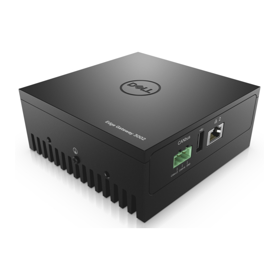
NOTE: The IG signal can be used to gracefully shutdown or enter low-power state when the vehicle is turned off (battery powered). It can also be used for powering on the Edge Gateway when the vehicle starts. Right view Table 6. Right view—3002 Features CANbus port Enables the CANbus connection. -
Page 11: Installing Your Edge Gateway
WARNING: Before you begin any of the procedures in this section, read the safety and regulatory information that is shipped with your system. For additional best practices information, go to www.dell.com/regulatory_compliance. Safety and regulatory information WARNING: The Edge Gateway must be installed by knowledgeable, skilled persons familiar with local and/or international electrical codes and regulations. -
Page 12: Professional Installation Instructions
Professional installation instructions Installation personnel This product is designed for specific applications and needs to be installed by qualified personnel with RF and regulatory-related knowledge. The general user shall not attempt to install or change the setting. Installation location The product shall be installed at a location where the radiating antenna is kept 20 cm from nearby persons in its normal operation condition in order to meet regulatory RF exposure requirements. -
Page 13: Industry Canada Statement
may cause harmful interference to radio communications. However, there is no guarantee that interference will not occur in a particular installation. If this equipment does cause harmful interference to radio or television reception, which can be determined by turning the equipment off and on, the user is encouraged to try to correct the interference by one of the following measures: •... -
Page 14: Setting Up Your Edge Gateway
La fonction de sélection de l'indicatif du pays est désactivée pour les produits commercialisés aux États-Unis et au Canada. Radiation Exposure Statement: This equipment complies with IC radiation exposure limits set forth for an uncontrolled environment. This equipment should be installed and operated with minimum distance of 20 cm between the active transceiver and your body. Déclaration d'exposition aux radiations: Cet équipement est conforme aux limites d'exposition aux rayonnements IC établies pour un environnement non contrôlé. - Page 15 3002 NOTE: Use only the supplied antennas or third-party antennas that meet the minimum specifications. NOTE: Depending on the configuration ordered, some of the antenna connectors may not be present or may be capped. NOTE: Mobile broadband antenna connector two is for LTE Auxiliary only; it does not support 3G. Insert the antenna into the connector.
- Page 16 CAUTION: Dell recommends that you insert the micro-SIM card before turning on the Edge Gateway. NOTE: Ensure that you firmly screw back the access door after closing. NOTE: Contact your service provider to activate your micro-SIM card.
- Page 17 NOTE: Secondary enclosures are sold separately. 10. Connect the Edge Gateway to one of the following power sources: • DC-IN •...
- Page 18 Ubuntu Core 16 Use the dcc.cctk command to access the Dell Command | Configure application. NOTE: For more information about using the Dell Command | Configure application, see the Dell Command | Installation Guide and User's Guide at www.dell.com/dellclientcommandsuitemanuals. Configure...
-
Page 19: Activating Your Mobile Broadband Service
• VESA mount Activating your mobile broadband service CAUTION: Before you power on the Edge Gateway, insert a micro-SIM card. NOTE: Ensure that the service provider has already activated the micro-SIM card before you use it in the Edge Gateway. Remove the screw to open the micro-SIM card access door. -
Page 20: Mounting Your Edge Gateway
Example (AT&T): network-manager.nmcli con add type gsm ifname cdc-wdm0 con-name ATT_GSMDEMO apn broadband Example (3G): network-manager.nmcli con add type gsm ifname cdc-wdm0 con-name 3G_GSMDEMO apn internet Connect to the mobile network: Command line: network-manager.nmcli con upExample (Verizon): network-manager.nmcli con up VZ_GSMDEMO Example (AT&T): network-manager.nmcli con up ATT_GSMDEMO Example (3G):... - Page 21 NOTE: The mounting brackets are shipped with only those screws that are required for securing the mounting brackets to the Edge Gateway. Secure the standard-mount bracket to the back of the Edge Gateway using the four M4x4.5 screws. NOTE: Torque the screws at 8±0.5 kilograms-centimeter (17.64±1.1 pounds-inch).
- Page 22 Place the Edge Gateway against the wall, and align the holes in the standard-mount bracket with the holes on the wall. Screw holes on the bracket have a diameter of 3 mm (0.12 in).
- Page 23 Place the standard-mount bracket on the wall, and using the holes above the screw holes on the bracket, mark the positions to drill the four holes.
- Page 24 Drill four holes in the wall as marked. Insert and tighten four screws (not supplied) to the wall. NOTE: Purchase screws that fit the diameter of the screw holes.
- Page 25 Align the screw holes on the standard-mount bracket with the screws and place the Edge Gateway onto the wall.
- Page 26 Tighten the screws to secure the assembly to the wall.
-
Page 27: Mounting The Edge Gateway Using Quick-Mount Bracket
Mounting the Edge Gateway using quick-mount bracket The quick-mount bracket is a combination of the standard-mount bracket and the DIN-rail bracket. It enables you to easily mount and demount the Edge Gateway. NOTE: The mounting brackets are shipped with only those screws required for securing the mounting brackets to the Edge Gateway. - Page 28 Mounting instructions Place the standard-mount bracket on the wall, and using the holes above the screw holes on the bracket, mark the positions to drill the four holes.
- Page 29 Drill four holes in the wall as marked. Insert and tighten four screws (not supplied) to the wall. NOTE: Purchase screws that fit the diameter of the screw holes.
- Page 30 Align the screw holes on the standard-mount bracket with the screws on the wall, letting the bracket hang on the screws.
- Page 31 Tighten the screws to secure the assembly to the wall.
- Page 32 Align the screw holes on the DIN-rail bracket with the screw holes at the back of the Edge Gateway. Place the two M4x5 screws on the DIN-rail bracket and secure it to the Edge Gateway.
- Page 33 Place the Edge Gateway on the standard mount at an angle, and then pull the Edge Gateway down to compress the springs at the top of the DIN-rail bracket.
- Page 34 Push the Edge Gateway towards the DIN-rail to secure it on the standard-mount bracket.
-
Page 35: Attaching The Cable Control Bars To The Standard-Mount Bracket
NOTE: For more information about demounting the DIN-rail, see Demounting DIN rail. Attaching the cable control bars to the standard-mount bracket Mount the Edge Gateway on the wall using the standard-mount bracket quick-mount bracket. Place the cable control bar on the mounting bracket and secure it to the notch. CAUTION: Use the top cable control bar only with coaxial cable connections. - Page 36 Align the screw holes on the cable control bar with the screw holes on the mounting bracket. Tighten the six M3x3.5 mm screws that secure the cable control bar to the mounting bracket. NOTE: Torque the screws at 5±0.5 kilograms-centimeter (11.02±1.1 pounds-inch).
- Page 37 Connect the cables to the Edge Gateway. Loop the cable lock (not supplied) to secure each cable to the cable control bar.
-
Page 38: Mounting The Edge Gateway On A Din Rail Using The Din-Rail Bracket
Mounting the Edge Gateway on a DIN rail using the DIN-rail bracket NOTE: The DIN-rail bracket includes the screws that are required for securing the bracket to the Edge Gateway. Align the screw holes on the DIN-rail bracket with the screw holes at back of the Edge Gateway. Place the two M4x5 screws on the DIN-rail bracket and secure it to the Edge Gateway. - Page 39 Secure the DIN-rail mounting bracket to the Edge Gateway using the two M4x5 screws provided. NOTE: Torque the screws at 8±0.5 kilograms-centimeter (17.64±1.1 pounds-inch) on the DIN-rail mounting bracket.
- Page 40 Place the Edge Gateway on the DIN rail at an angle, and then pull the Edge Gateway down to compress the springs at the top of the DIN-rail mounting bracket. Push the Edge Gateway towards the DIN-rail to secure the lower clip of the bracket onto the DIN rail.
-
Page 41: Mounting The Edge Gateway Using The Perpendicular Mount
NOTE: For more information about demounting the DIN-rail, see Demounting DIN rail. Mounting the Edge Gateway using the perpendicular mount NOTE: The perpendicular mount is designed for mounting in a DIN-rail only. NOTE: An open space of 63.50 mm (2.50 in) around the Edge Gateway is recommended for optimal air circulation. Ensure that the environmental temperature in which the Edge Gateway is installed does not exceed the operating temperature of the Edge Gateway. - Page 42 Align the screw holes on the DIN-rail mount bracket with the screw holes on the perpendicular-mount bracket, and tighten the two screws. NOTE: Torque the screws at 8±0.5 kilograms-centimeter (17.64±1.1 pounds-inch).
- Page 43 Place the Edge Gateway on the DIN rail at an angle and push the Edge Gateway down to compress the springs on the DIN-rail mount brackets. Push the Edge Gateway towards the DIN-rail to secure the lower clip of the bracket onto the DIN rail.
-
Page 44: Mounting The Edge Gateway Using A Vesa Mount
Secure the Edge Gateway on the DIN rail. Mounting the Edge Gateway using a VESA mount The Edge Gateway can be mounted on a standard VESA mount (75 mm x 75 mm). NOTE: The VESA mount option is sold separately. For VESA mounting instructions, see the documentation that is shipped with the VESA mount. -
Page 46: Setting Up The Zigbee Dongle
Setting up the ZigBee dongle CAUTION: Do not connect the ZigBee dongle if the Edge Gateway is installed inside the enclosure. Power off your Edge Gateway. Connect the ZigBee dongle to any external USB port on your Edge Gateway. Power on your Edge Gateway and complete the setup. NOTE: For more information about the ZigBee development, see www.silabs.com. -
Page 47: Setting Up The Operating System
Setting up the operating system CAUTION: To prevent operating system corruption from sudden power loss, use the operating system to gracefully shut down the Edge Gateway. The Edge Gateway is shipped with one of the following operating systems: • Windows 10 IoT Enterprise LTSB 2016 •... -
Page 48: Restoring Windows 10 Iot Enterprise Ltsb 2016
Cloud LED NOTE: To utilize the Cloud LED, download the necessary tools and drivers from www.dell.com/support. One unique feature of the Edge Gateway 3000 Series is the Cloud LED. Cloud LED enables you to visually inspect the operational status of the Edge Gateway by looking at the display light on the left panel of the Edge Gateway. -
Page 49: Ubuntu Core 16
DCSTL64.cat CloudLED.exe NOTE: These files must be in the same directory. Run the CloudLED.exe from Command Prompt or PowerShell with administrative rights. Run the following commands: • CloudLED.exe ON • CloudLED.exe OFF TPM support Windows 10 IoT Enterprise LTSB 2016 supports TPM 2.0. For more information about TPM resources, see technet.microsoft.com/en-us/library/cc749022. -
Page 50: Boot Up And Log In – Remote System Configuration
Set the subnet mask to 255.255.255.0. Updating operating system and applications After enabling the network connections and connecting to the internet, Dell recommends to have the latest OS components and applications installed. To update Ubuntu Core 16, run: admin@localhost:~$ sudo snap refresh... -
Page 51: Additional Ubuntu Commands
Additional Ubuntu commands Basic commands NOTE: For more information about Ubuntu commands, see https://snapcraft.io/. Table 9. Basic commands Action Ubuntu Core 16 Viewing system attributes #sudo snap version Updating the image to the latest release #sudo snap update Viewing a list of all the snaps that are currently installed #sudo snap find Viewing a set and attribute to a snap #sudo snap set... -
Page 52: Ubuntu Network Manager
Run the command: admin@localhost:$ cat /sys/class/dmi/id/ board_vendor returns Dell Inc. The system tag is printed. Ubuntu Network Manager Network-Manager is a native Ubuntu Snappy connection manager. The application can be used to configure the Edge Gateway so that it's automatically-detected and connected to the network. The application can be used to configure multiple network devices. - Page 53 Show a list of network interfaces like eth0, eth1, wlan0, mlan0, and so on. $ network-manager.nmcli d Show a list of available wireless access points. $ network-manager.nmcli device wifi list Wireless connection with nmcli: Run the following commands and replace $SSID, $PSK, and $WIFI_INTERFACE with the variables for your environment.
- Page 54 [NEW] Device XX:XX:XX:XX:XX:XX MYCLIENT [bluetooth]# scan off Pair with each other. As of Bluetooth v2.1, Secure Simple Pairing is a requirement, and offers three methods of pairing devices, which are applicable on the Dell Gateway 3000 series: • Just Works...
-
Page 55: Security
Linux-Watchdog.html. Dell recommends that you enable the WDT by default to activate the fail-safe circuitry. Snappy, a WDT-compatible operating system, provides the capability to detect and recover the system from malfunctions or unexpected crashes. To check daemon status, run the command:... -
Page 56: Cloud Led On/Off
Returns: RuntimeWatchdogUSec=1min ShutdownWatchdogUSec=10min NOTE: The default value is 10. The actual value should be greater than 0. To configure WDT, run the command: admin@localhost:$ sudo vi /etc/systemd/system.conf.d/watchdog.conf Cloud LED On/Off To export Cloud LED PIN, run the command: #sudo su – #echo 346 >... - Page 57 Select Advanced, then select proceed to the ip_address(unsafe). Using the default login of 'admin', keeping the password blank, open Terminal and ssh remote login lo@lo-latitude-E7470:~$ ssh [email protected] [email protected]'s password: While running sudo snapweb.generate-token, copy the token. lo@lo-latitude-E7470:~$ ssh [email protected] [email protected]'s password: Welcome to Ubuntu 16.04.1 LTS (GNU/Linux 4.4.0-45-generic x86_64) * Documentation: https://help.ubuntu.com * Management:...
-
Page 58: Can Module
You can now access the snapweb. CAN module NOTE: For information about using the CAN module, see the documentation available at www.atmel.com. The Edge Gateway supports the CANbus model Atmel ATSAME70N19A-CNT. This feature is only supported if the hardware module is present, and the operating system provides the capability of mutual communication between user space application and physical module. -
Page 59: Ignition Pin
• To retrieve data from the motion sensor, run the command. $ cat in_accel_scale_available $ cat in_accel_*_scale $ cat in_accel_*_raw • To retrieve data from the pressure sensor, run the command. $ cat in_pressure_raw $ cat in_pressure_scale Converting raw data for use Apply the formula in the table to convert the raw data collected into usable measurements. -
Page 60: System Power Management
For example, to reboot the system when the power button is pressed, run the command: $ snap set core system.power-key-action=reboot System Power Management Configuring low power states: S3 and S4 Configure sleep state–S3 $ sudo systemctl suspend Configure hibernate state–S4 $ sudo systemctl hibernate Rebooting or power off To reboot the system... - Page 61 Run the following command to trigger native eMMC recovery partition:. $ sudo efibootmgr -n $(efibootmgr | grep "factory_restore" | sed 's/Boot//g' | sed 's/ [^0-9A-B]*//g') ; reboot Option 2: Restoring during system POST CAUTION: These steps delete all the data on your Edge Gateway. Connect a USB keyboard to the Edge Gateway.
-
Page 62: Flashing A New Os Image
• Service Tag of the Edge Gateway • A Windows computer with administrator rights and at least 8 GB of available storage space to download the Dell ISO recovery image • A blank USB flash drive with at least 8 GB of storage space. These steps delete all data on the USB flash drive. -
Page 63: Can Module
Connect the USB flash drive to the computer. Click Browse and navigate to the location where the Dell ISO recovery image file is saved. Select the Dell ISO recovery image file and click Open. Click Start to begin creating the bootable USB recovery media. -
Page 64: Accessing And Updating Bios
Use Dell Command | Configure (DCC) to access BIOS settings Dell Command | Configure (DCC) is a factory-installed application in the Edge Gateway that helps to configure the BIOS settings. It consists of a Command Line Interface (CLI) to configure various BIOS features. For more information about DCC, see www.dell.com/dellclientcommandsuitemanuals. -
Page 65: Flashing The Bios From A Usb Flash Drive
The fwupgmgr tool or commands are used to update the UEFI BIOS on the system. The UEFI BIOS for this platform is released through online Linux Vendor File System (LVFS) based methods Dell recommends that you enable the UEFI Capsule update by default so that it is running in the background to keep the system BIOS up to date. -
Page 66: Dell Command | Configure (Dcc)
(only for Edge Gateway 3002 and 3003) Check the current BIOS details. $sudo uefi-fw-tools.fwupdmgr get-devices Check if the update is available from LVFS service. $sudo uefi-fw-tools.fwupdmgr refresh Download the BIOS from the www.dell.com/support. $sudo uefi-fw-tools.fwupdmgr get-updates Apply the update. $sudo uefi-fw-tools.fwupdmgr update -v Restart the system. -
Page 67: Default Bios Settings
Default BIOS settings System configuration (BIOS level 1) Table 17. System configuration (BIOS level 1) BIOS level 2 BIOS level 3 Item Default value Integrated NIC Integrated NIC Enable UEFI Network Stack Enabled [Enable/Disable] [Disabled, Enabled, Enabled w/ Enabled w/PXE PXE] Integrated NIC 2 [Disabled, Enabled]... - Page 68 BIOS level 2 BIOS level 3 Item Default value Confirm new password Not applicable System Password System Password Enter the old password Not Set Enter the new password Not applicable Confirm new password Not applicable Strong Password Strong Password Enable Strong Password Disabled [Enable/Disable] Password Configuration...
-
Page 69: Secure Boot (Bios Level 1)
Secure boot (BIOS level 1) Table 19. Secure boot (BIOS level 1) BIOS level 2 BIOS level 3 Item Default value Secure Boot Enable Secure Boot Enable [Enable/Disable] Disabled Expert Key Management Expert Key Management Enable Custom Mode [Enable/ Disabled Disable] Custom Mode Key Management {PK/KEK/db/... -
Page 70: Post Behavior (Bios Level 1)
POST behavior (BIOS level 1) Table 22. POST behavior (BIOS level 1) BIOS level 2 BIOS level 3 Item Default value Numlock LED Numlock LED Enable Numlock LED [Enable/ Enabled Disable] Keyboard Errors Keyboard Errors Enable Keyboard Error Enabled Detection [Enable/Disable] Fastboot Fastboot [Minimal/Thorough/Auto]... - Page 71 System logs (BIOS level 1) Table 25. System logs (BIOS level 1) BIOS level 2 BIOS level 3 Item Default value BIOS Events BIOS Events List of BIOS events with "Clear Not applicable Log" button to clear the log...
-
Page 72: References
Dell Command | Configure Reference Guide • Dell Command | Monitor User's Guide • Dell Command | PowerShell Provider User's Guide For more information on using Dell Data Protection | Encryption see the documentation for the software at www.dell.com/ support/manuals. -
Page 73: Appendix
NOTE: Use only the supplied or an approved replacement antenna. NOTE: Modifications to the device or use of unauthorized antennas not expressly approved by Dell is the sole responsibility of the user or configurator or operator to reassess the equipment in accordance to all applicable international Safety, EMC, and RF standards. -
Page 74: De-Mounting From Din-Rail Bracket
Table 27. Mobile broadband auxiliary antenna maximum gain (dBi) Antenna position—Bent Antenna position—Straight Frequency (MHz) 4G (dBi) 4G (dBi) 704~806 824~894 –0.8 –0.1 880~960 –0.6 –2.5 1710~1880 1850~1990 1920~2170 Table 28. WiFi/GPS antenna maximum gain (dBi) Antenna position—Bent Antenna position—Straight Frequency (MHz) GPS (dBi) WLAN (dBi) -
Page 75: Connecting To The Edge Gateway
Connecting to the Edge Gateway Windows 10 IoT Enterprise LTSB 2016 Boot up and login – Remote system configuration NOTE: Your computer must be on the same subnet as the Edge Gateway. Connect a network cable from Ethernet port one on the Edge Gateway to a DHCP-enabled network or router that provides IP addresses. - Page 76 For example; Ubuntu Core 16 on 127.0.0.1 (tty1) localhost login: admin Password: admin Boot up and log in – Static IP system configuration This allows you to connect your Edge Gateway through a host computer, which must be on the same subnet. NOTE: The static IP address of Ethernet port two on the Edge Gateway is set to these values at the factory: •...
-
Page 77: Contacting Dell
Go to www.dell.com/contactdell. Verify your country or region in the drop-down list at the bottom of the page. Select the appropriate service or support link based on your requirement or choose the method of contacting Dell that is convenient for you.