Quick Links
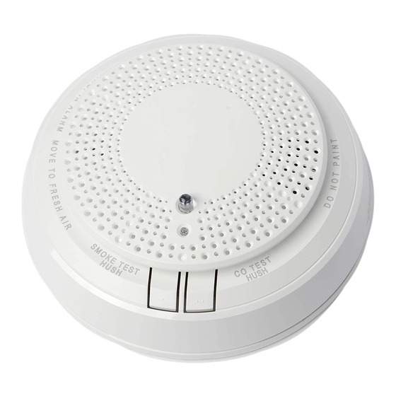
Model: 5800COMBO with voice and 360 degree viewable LED ring
Combination Smoke/Carbon Monoxide (CO) Detector with Built-in Wireless Transmitter
This is intended for use with Honeywell control
panels that support 5800 series devices.
Install
• Remove Battery Pull tabs to activate device and
begin enrollment.
The detector will run through its Power-Up
•
mode: Green LED Blinks every 2 secs /
Sounder is Silent. The detector will prompt for
language selection.
Important Note: CO and SMOKE each have
unique serial numbers and must to be enrolled
separately.
Enroll
Press the Smoke (•) test button to select English or the CO
1.
(••) test button to select Spanish language settings.
On the Honeywell compatible control panel, log in
2.
Programming Mode > Zones > New > Serial Number.
Enter the zone number to be programmed for Smoke.
3.
Enter zone type when prompted. Program:
4.
• Loop 1 (Heat/Smoke) as a Fire zone (type 9 or 16),
• Loop 2 (High/Low Maintenance) as a 24-Hr. Trouble zone
(type 19),
• Loop 3 (Freeze Warning Sensor) as a 24-Hr. Aux. zone
(type 8).
NOTE: Loop 2 High/Low Maintenance is supported only on
commercial control panels such as the Vista-128FBP.
When prompted, enter Input Type 03 (3 on some controls) –
5.
Supervised RF Transmitter.
When prompted for the serial number, activate the sensor
6.
(press for 1 sec.) or enter the serial number found on the
label located on the unit. The unit will speak, then beep and
the serial number will be transmitted to the panel. (This will
take approx. 40 secs.) Repeat this step to complete
enrollment.
The current loop number (4) will begin to flash.
7.
Manually change the loop number to the desired loop
8.
number for the zone, loop (1) is for Heat/Smoke.
When programming for the Heat/Smoke Loop 1 zone type is
9.
complete, program other zones for the types as necessary in
additional zones (except for Tamper Loop 4, which does not
require programming).
WARNING: The fire protection zone enrolled must always be Loop
1. Otherwise, fire annunciations will not be reported by the control.
Enter the zone number to be programmed for CO.
10.
Enter the applicable zone type. Use zone type 14 for
11.
Honeywell residential controls.
Enter Input Type 03 (3 on some controls)–Supervised RF
12.
Transmitter.
When prompted for the serial number, activate the sensor
13.
(press for 1 sec.) or enter the serial number found on the
label located on the unit. The unit will speak, then beep and
the serial number will be transmitted to the panel. (This will
take approx. 40 secs.) Repeat this step to complete
enrollment.
Check that the CO detector is enrolled as loop 1.
14.
Exit Programming mode and test the detector. Refer
15.
to the Testing Section.
INSTALLATION AND SETUP GUIDE
( )
CO Test
LED
5800COMBO
1
( ) Spanish
Table 1: Operation Modes
MODE
(Standby)
Visible Annunciation
The 5800COMBO Smoke/CO series detector has a multi-color
top LED; Green, Red, Blue and Amber. The LED is green for
supervisory indication; it blinks during power on, reset, and
during normal operation. The LED is amber to signal
maintenance and trouble events. The detector utilizes the side
LED windows to indicate alarm events; red for smoke and blue
for CO.
( )
Smoke Test
5800combo-ii 001
Power -Up mode
( ) English
French
LED Flashes
3
Test
Press Test button for < 1.5 secs
3b) Test Smoke
3a) Test CO
or
LED Windows
Status LED
(Side)
(Top)
Blink Green,
Power Up
every 2 secs
Single Blink
Normal
Green every
10 secs
Smoke
Blink Red
Blink red
Alarm
every 10 secs
Thermal
Dark
Blink red
Alarm
Blink Red
CO Alarm
Blink blue
every 10 secs
Powered
Dark
Down
Open
Top
Pull Battery Tab
Open
2
Programming Mode
Zones > New > Serial Numbers.
Zone n
Serial Number
Loop Number
Zone Description 1
Zone Description 2
Enter the unique Serial number(s)
found on the label located on the
unit. See Important Note above.
4
Transmission announcment >
Beep > Serial # sent to panel
(approx. 40 secs)
Repeat Step 3.
5
Save
Speaker
Sounder
Voice welcome,
instructions follow
Dark
Silent
POR for language
selection, enrollment,
testing
Dark
Silent
Silent
Voice smoke
Temp-3
warning
Voice smoke
Temp-3
warning
Voice CO
Temp-4
warning
Dark
Silent
Silent

Related Manuals for Honeywell 5800COMBO


Summary of Contents for Honeywell 5800COMBO
- Page 1 Model: 5800COMBO with voice and 360 degree viewable LED ring Combination Smoke/Carbon Monoxide (CO) Detector with Built-in Wireless Transmitter INSTALLATION AND SETUP GUIDE This is intended for use with Honeywell control Open CO Test Smoke Test panels that support 5800 series devices.
- Page 2 Mounting After enrolling and before mounting permanently, conduct Go/No Go test (see controller’s instructions) to verify adequate signal strength. Adjust the device location as necessary. Physically mount the smoke detector in the desired location; 1. Using two supplied screws and anchors, mount the base. 2.
- Page 3 Maintenance The 5800COMBO detector reports maintenance issues to the control panel and communicates them visually and audibly per Table 2. Trouble feature: When the sensor (supervision) is in a trouble condition (such as a detector that is dirty or CO sensor non-functioning), the detector will send a trouble signal to the control panel.
- Page 4 émetteur doit être installée à une distance de séparation d'au Approval Listings: moins 7,8 pouces (20 cm) de toutes les personnes. This product is intended for use with Honeywell controls that support 5800 series devices. FCC / IC Listed to UL 268, UL 521 & UL 2075.