
Related Manuals for Dell EMC PowerEdge VRTX


Summary of Contents for Dell EMC PowerEdge VRTX
- Page 1 Dell Chassis Management Controller Version 3.0 for Dell EMC PowerEdge VRTX User's Guide...
- Page 2 WARNING: A WARNING indicates a potential for property damage, personal injury, or death. Copyright © 2017 Dell Inc. or its subsidiaries. All rights reserved. Dell, EMC, and other trademarks are trademarks of Dell Inc. or its subsidiaries. Other trademarks may be trademarks of their respective owners.
-
Page 3: Table Of Contents
Supported Management Console Applications ..............................23 How to use this Guide ............................. 23 Other Documents You May Need ..................... 24 Accessing documents from the Dell EMC support site 2 Installing and Setting Up CMC..................25 ................................25 Before You Begin ..............................25 Installing CMC Hardware ............................25... - Page 4 ..................33 Launching CMC Using Other Systems Management Tools ........................33 Downloading and Updating CMC Firmware .......................33 Setting Chassis Physical Location and Chassis Name ..............33 Setting Chassis Physical Location and Chassis Name Using Web Interface ...............33 Setting Chassis Physical Location and Chassis Name Using RACADM ............................33 Setting Date and Time on CMC ..................34...
- Page 5 4 Updating Firmware......................46 ............................46 Downloading CMC Firmware ........................46 Viewing Currently Installed Firmware Versions ..............46 Viewing Currently Installed Firmware Versions Using CMC Web Interface .................. 47 Viewing Currently Installed Firmware Versions Using RACADM ............................47 Updating the CMC Firmware .............................48 Signed CMC Firmware Image ........................
- Page 6 ..............................66 Viewing Chassis Summary ......................66 Viewing Chassis Controller Information and Status .......................66 Viewing Information and Health Status of All Servers .................... 66 Viewing Health Status and Information for Individual Server ......................67 Viewing Information and Health Status of the IOM ........................
- Page 7 ..........................81 Saving Server Inventory Report ......................82 Chassis Group Inventory and Firmware Version ..........................83 Viewing Chassis Group Inventory ...................83 Viewing Selected Chassis Inventory Using Web Interface ............83 Viewing Selected Server Component Firmware Versions Using Web Interface ............................83 Chassis Configuration Profiles .............................
- Page 8 .................................99 Exporting Profile ................................100 Editing Profile ................................. 100 Deleting Profile ............................100 Viewing Profile Settings ..........................101 Viewing Stored Profile Settings ..............................101 Viewing Profile Log ........................101 Completion Status And Troubleshooting .............................101 Quick Deploy of Profiles ..........................101 Assigning Server Profiles to Slots ..............................
- Page 9 ..................128 Configuring the Generic LDAP Directory to Access CMC ..............128 Configuring Generic LDAP Directory Service Using CMC Web Interface .................. 129 Configuring Generic LDAP Directory Service Using RACADM 10 Configuring CMC For Single Sign-On Or Smart Card Login........130 ..............................
- Page 10 ..................148 Viewing WWN or MAC Address Information Using RACADM ..............................149 Command Messages ....................150 FlexAddress DELL SOFTWARE LICENSE AGREEMENT 13 Managing Fabrics....................... 152 ..............................152 Fresh Power-up Scenario ..............................152 Monitoring IOM Health ........................... 152 Configuring Network Settings for IOM ................
- Page 11 ..........................164 Executing Power Control Operations ....................164 Executing Power Control Operations on the Chassis ............... 165 Executing Power Control Operations on the Chassis Using Web Interface ..............165 Executing Power Control Operations on the Chassis Using RACADM ......................165 Executing Power Control Operations on a Server ............
- Page 12 ........................178 Encrypting Virtual Disks Using RACADM ............................. 178 Unlocking Foreign Configuration ..................178 Unlocking Foreign Configuration Using CMC Web Interface ......................178 Unlocking Foreign Configuration Using RACADM ............................... 179 Cryptographic Erase ..........................179 Performing Cryptographic Erase ....................179 Applying Virtual Adapter Access Policy To Virtual Disks ..................
- Page 13 ....................195 Obtain Recovery Information from DB-9 Serial Port ............................195 Recovering Firmware Image ..........................196 Troubleshooting Network Problems .............................. 196 Troubleshooting Controller ......................196 Hotplugging enclosures in fault-tolerant chassis 18 Using LCD Panel Interface..................198 ................................198 LCD Navigation ................................199 Main Menu ..............................199 KVM Mapping Menu ................................
-
Page 14: Overview
Overview The Dell Chassis Management Controller (CMC) for Dell EMC PowerEdge VRTX is a Systems Management hardware and software solution for managing the PowerEdge VRTX chassis. The CMC has its own microprocessor and memory and is powered by the modular chassis into which it is plugged. -
Page 15: What Is New In This Release
Firmware update of server components such as BIOS, network controllers, storage controllers, and so on across multiple servers in the chassis using Lifecycle Controller. • Dell OpenManage software integration — Enables you to launch the CMC web interface from Dell OpenManage Server Administrator or OpenManage Essentials (OME) 1.2. •... -
Page 16: Security Features
• Configure storage components on the chassis. • Map PCIe slots to the servers and their identification. Security Features The CMC provides the following security features: • Password-level security management — Prevents unauthorized access to a remote system. • Centralized user authentication through: –... - Page 17 Item Indicator, Button, or Connector Status/identification indicator (CMC 2) A Back Panel view of the chassis is given here with a table that lists the parts and devices available in the CMC. Figure 2. CMC back panel Table 2. CMC back panel — parts Item Indicator, Button, or Connector PCIe expansion card slots low-profile (5)
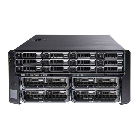
- Page 18 Figure 3. Front-Panel Features And Indicators—3.5 Inch Hard Disk Drive Chassis Table 3. Front panel — features and indicators Item Indicator, Button, or Connector Description USB connectors (2) Allows a keyboard and mouse to be connected to the system. LCD panel Provides system information and status, and error messages to indicate when the system is operating correctly or when the system needs attention.
-
Page 19: Minimum Cmc Version
Item Indicator, Button, or Connector Description Server modules Up to four PowerEdge M520, M620, M630, or M640 server modules or 2 M820 server modules configured for the enclosure. Minimum CMC Version The following table lists the minimum CMC version required to enable the listed server modules. Table 4. -
Page 20: Supported Web Browsers
For the latest supported platforms, see the Dell Chassis Management Controller (CMC) Version 3.0 for Dell PowerEdge VRTX Release Notes available at dell.com/support/manuals. Supported Web Browsers The following web browsers are supported for Dell PowerEdge VRTX: • Microsoft Internet Explorer 9 •... -
Page 21: License Component State Or Condition And Available Operations
Learn More — Learn more about an installed license, or the licenses available for a component installed in the server. NOTE: For the Learn More option to display the correct page, make sure that *.dell.com is added to the list of Trusted Sites in the Security Settings. - Page 22 Table 8. Licensable features Feature Express Enterprise Notes CMC Network CMC Serial Port RACADM (SSH, Local, and Remote) CMC Setup Backup CMC Setup Restore WS-MAN SNMP Telnet Web-based Interface Email Alerts LCD Deployment Extended iDRAC Management Yes Remote Syslog Directory Services *For non-default directory service setting, only Reset Directory Services is allowed with an Express license.
-
Page 23: Viewing Localized Versions Of The Cmc Web Interface
RACADM command, see the Chassis Management Controller for PowerEdge VRTX RACADM Command Line Reference Guide available at dell.com/cmcmanuals. Other Documents You May Need To access the documents from the Dell Support site. Along with this Reference Guide, you can access the following guides available at dell.com/support/manuals. •... -
Page 24: Accessing Documents From The Dell Emc Support Site
Regulatory Compliance home page at www.dell.com/regulatory_compliance. Warranty information may be included within this document or as a separate document. • The Dell PowerEdge VRTX Getting Started Guide shipped with your system provides an overview of system features, setting up your system, and technical specifications. •... -
Page 25: Installing And Setting Up Cmc
Before setting up your CMC environment, download the latest version of CMC firmware for PowerEdge VRTX from dell.com/ support/. Also, make sure that you have the Dell Systems Management Tools and Documentation DVD that was included with your system. Installing CMC Hardware CMC is pre-installed on your chassis and hence no installation is required. -
Page 26: Basic Cmc Network Connection
For information about installing Dell OpenManage software components, see the Dell OpenManage Installation and Security User's Guide available on the DVD or at dell.com/support/manuals. You can also download the latest version of the Dell DRAC Tools from support.dell.com. -
Page 27: Configuring A Web Browser
You can configure and manage CMC, servers, and modules installed in the chassis through a web browser. See the “Supported Browsers" section in the Dell Systems Software Support Matrix at dell.com/support/manuals. The CMC and the management station where you use your browser must be on the same network, which is called the management network. -
Page 28: Certificate Revocation List Fetching
Certificate Revocation List Fetching If your CMC has no access to the Internet, disable the certificate revocation list (CRL) fetching feature in Internet Explorer. This feature tests whether a server such as the CMC web server uses a certificate that is on a list of revoked certificates retrieved from the Internet. -
Page 29: Configuring Initial Cmc Network
If you configure initial network settings after the CMC has an IP address, you can use any of the following interfaces: • Command line interfaces (CLIs) such as a serial console, Telnet, SSH, or the Dell CMC console. • Remote RACADM •... - Page 30 For effective network throughput, the network speed setting must match your network configuration. Setting the network speed lower than the speed of your network configuration increases bandwidth consumption and slows down the network communication. Determine whether or not your network supports the above network speeds and set it accordingly. If the network configuration does not match any of these values, it is recommended to select the Auto (1 Gb) option, or refer to your network equipment manufacturer's user documentation.
-
Page 31: Interfaces And Protocols To Access Cmc
Table 9. Network mode Dynamic Host Configuration iDRAC retrieves IP configuration (IP address, mask, and gateway) automatically from a DHCP Protocol (DHCP) server on your network. The iDRAC is assigned a unique IP address allotted over your network. Press the center button. The IPMI Over LAN panel is displayed. Static If you select Static, manually enter the IP address, gateway, and subnet mask by following the instructions on the LCD screen. - Page 32 CMC firmware and is accessed through the NIC interface from a supported web browser on the management station. For a list of supported Web browsers, see the “Supported Browsers” section in the Dell System Software Support Matrix at dell.com/support/manuals.
-
Page 33: Launching Cmc Using Other Systems Management Tools
Setting Chassis Physical Location and Chassis Name You can set the chassis location in a data center and the chassis name to identify the chassis on the network (default name is Dell Rack System). For example, an SNMP query on the chassis name returns the name you configure. -
Page 34: Setting Date And Time On Cmc Using Cmc Web Interface
To set the date and time using the command line interface, see the config command and cfgRemoteHosts database property group sections in the Chassis Management Controller for PowerEdge VRTX RACADM Command Line Reference Guide available at dell.com/support/manuals. Configuring LEDs to Identify Components on the Chassis You can enable the LEDs of components (chassis, servers, physical disk drives, virtual disks, and I/O Modules) to blink so that you can identify the component on the chassis. -
Page 35: Configuring Cmc Properties
Configuring iDRAC Launch Method Using RACADM To update CMC firmware using RACADM, use the cfgRacTuneIdracDNSLaunchEnable subcommand. For more information, see the Chassis Management Controller for PowerEdge VRTX RACADM Command Line Reference Guide available at dell.com/ support/manuals. Configuring Login Lockout Policy Attributes Using CMC Web Interface NOTE: To perform the following tasks, you must have Chassis Configuration Administrator privilege. -
Page 36: Understanding Redundant Cmc Environment
• Run the RACADM cmcchangeover command. See the cmcchangeover command section in the Chassis Management Controller for PowerEdge VRTX RACADM Command Line Reference Guide available at dell.com/support/manuals. • Run the RACADM racreset command on the active CMC. See the racreset command section in the Chassis Management Controller for PowerEdge VRTX RACADM Command Line Reference Guide available at dell.com/support/manuals.. -
Page 37: Active Cmc Election Process
• You cannot turn on the newly installed servers. • You cannot remotely access existing servers. • Server performance reduces to limit power consumption until management of the CMC is restored. The following are some of the conditions that can result in CMC management loss: •... -
Page 38: Accessing A Server Using Kvm
• From the LCD Language drop-down menu, select the required language. • From the LCD Orientation drop-down menu, select the required mode — Tower Mode or Rack Mode. NOTE: When you configure the chassis by using the LCD wizard, if you select the Auto-Apply settings to newly inserted servers option, you cannot disable the Auto-Apply settings to newly inserted servers function by using a basic license. -
Page 39: Logging In To Cmc
To access the CMC web interface: Open a web browser supported on your system. For the latest information on supported web browsers, see the Dell Systems Software Support Matrix located at dell.com/ support/manuals. In the Address field, type the following URL, and then press: •... -
Page 40: Logging In To Cmc Using A Smart Card
• CMC user name:• Active Directory user name: \ , / or @ . • LDAP user name: NOTE: This field is case-sensitive. In the Password field, type the user password. NOTE: For Active Directory user, the Username field is case-sensitive. From the drop-down menu of the Domain field, select the required domain. -
Page 41: Logging In To Cmc Using Single Sign-On
RACADM provides a set of commands that allow you to configure and manage CMC through a text-based interface. RACADM can be accessed using a Telnet/SSH or serial connection, using the Dell CMC console on the KVM, or remotely using the RACADM command line interface installed on a management station. -
Page 42: Logging In To Cmc Using Public Key Authentication
You can use remote RACADM commands in scripts to configure multiple CMCs. You cannot run the scripts directly on the CMC web interface, because CMC does not support it. For more information about RACADM, see the Chassis Management Controller for PowerEdge VRTX RACADM Command Line Reference Guide. -
Page 43: Changing Default Login Password Using Web Interface
To enable the display of the warning message to change the default login password using RACADM, use racadm config -g cfgRacTuning -o cfgRacTuneDefCredentialWarningEnable<0> or <1> object. For more information, see the Chassis Management Controller for PowerEdge VRTX RACADM Command Line Reference Guide available at dell.com/support/ manuals. -
Page 44: Use Case Scenarios
Conversion of External Shared PERC 8 card High Availability to Non-High Availability Mode using RACADM Dell PowerEdge VRTX chassis must have 2 External Shared PERC 8 cards in PCI slot 5 and PCI slot 6 must be in HA mode. Workflow Power down chassis. -
Page 45: Conversion Of External Shared Perc 8 Card Non-High Availability To High Availability Mode Using Racadm
Conversion of External Shared PERC 8 card Non-High Availability to High Availability Mode using RACADM Dell PowerEdge VRTX chassis must have External Shared PERC 8 cards in PCI slot 5 and PCI slot 6. Workflow Power down chassis. Disconnect all SAS cables from External Shared PERC 8 cards to MD12x0 enclosures. -
Page 46: Updating Firmware
Internal Storage Backplane firmware and external enclosure's expanders HDD firmware (external and integrated enclosures) For more information about the update sequence for VRTX chassis, see the CMC Firmware 3.0 Release Notes available at dell.com/ cmcmanuals. Viewing Currently Installed Firmware Versions You can view the currently installed firmware versions using the CMC web interface or RACADM. -
Page 47: Viewing Currently Installed Firmware Versions Using Racadm
• Chassis Overview → Update • Chassis Overview → Chassis Controller → Update • Chassis Overview → Server Overview → Server Component Update • Chassis Overview → I/O Module Overview → Update • Chassis Overview → Storage → Storage Component Update The Firmware Update page displays the current version of the firmware for each listed component and allows you to update the firmware to the latest version. -
Page 48: Signed Cmc Firmware Image
NOTE: • To view the MD12x0 cabling diagram, refer to Upgrading PowerEdge VRTX to Support Shared Storage Expansion User's Guide or Dell Shared PowerEdge RAID Controller (PERC) 8 Cards For Dell PowerEdge VRTX Systems User’s Guide available at dell.com/support/manuals. •... -
Page 49: Updating Cmc Firmware Using Web Interface
Updating CMC Firmware Using Web Interface NOTE: • Before applying the CMC update, ensure that the chassis is powered on. If the blades are powered on, it is not necessary to power off the blades to perform the CMC update. •... -
Page 50: Updating Chassis Infrastructure Firmware Using Racadm
• Chassis Overview → Update. • Chassis Overview → Chassis Controller → Update. On the Firmware Update page, in the Chassis Infrastructure Firmware section, in the Update Targets column, select the option, and then click Apply Chassis Infrastructure Firmware. On the Firmware Update page, click Browse, and then select the appropriate chassis infrastructure firmware. Click Begin Firmware Update, and then click Yes. -
Page 51: Updating Server Component Firmware
The Single Click all blade update or the Update from Network Share method enables you to update the server component firmware using DUP files stored on a network share. You can use the Dell Repository Manager (DRM) based update feature to access the DUP files stored on a network share and update the server components in a single operation. -
Page 52: Server Component Update Sequence
• You can copy the directories of updates from the Dell Server Update Utility (SUU) download DVD or create and customize the required update versions in the Dell Repository Manager (DRM). You do not need the latest version of the Dell Repository Manager to create this directory. -
Page 53: Choosing Server Component Firmware Update Type Using Cmc Web Interface
NOTE: Automatic filtering feature is important while using the Dell Update Package (DUP). The update programming of a DUP can be based on the type or model of a component or device. The automatic filtering behavior is designed to minimize the subsequent selection decisions after an initial selection is made. -
Page 54: Viewing Firmware Inventory
-l [-m] [-f ] For more information, see the Chassis Management Controller for PowerEdge VRTX RACADM Command Line Reference Guide available at dell.com/support/manuals. Viewing Firmware Inventory You can view the summary of the firmware versions for all components and devices for all servers currently present in the chassis along with their status. -
Page 55: Viewing Firmware Inventory Using Racadm
Viewing Firmware Inventory Using RACADM To view firmware inventory using RACADM, use the getversion command: racadm getversion -l [-m] [-f ] For more information, see the Chassis Management Controller for PowerEdge VRTX RACADM Command Line Reference Guide available at dell.com/support/manuals. -
Page 56: Saving Chassis Inventory Report Using Cmc Web Interface
The Inventory.xml file is saved on an external system. Inventory.xml file as an input to create a repository of NOTE: The Dell Repository Manager Application uses the updates for all the blades available in the chassis. This repository can be later exported to a network share. Update from Network Share mode of firmware update uses this network share to update the components of all the servers. -
Page 57: Reinstalling Server Component Firmware
• Rollback • Update • Delete Jobs Only one type of operation can be performed at a time. Components and devices that are not supported may be listed as part of the inventory, but do not permit Lifecycle Controller operations. To perform the Lifecycle Controller operations, you must have: •... -
Page 58: Upgrading Server Component Firmware
NOTE: The update size limitation of either a single DUP or combined DUPs can be ignored if the Extended Storage feature is installed and enabled. For information on enabling extended storage, see Configuring CMC Extended Storage Card. Specify the firmware image file for the selected component(s) or devic(es). This is a Microsoft Windows Dell Update Package (DUP) file. -
Page 59: Server Component Single Click Update Using Network Share
NFS. This method provides a quick and easy way to build a custom repository for connected systems that you own using the Dell Repository Manager and the chassis inventory file exported using the CMC Web interface. DRM enables you to create a fully customized repository that only includes the update packages for the specific system configuration. -
Page 60: Supported Firmware Versions For Server Component Update
NOTE: Click Collapse against a slot to collapse the component and device firmware details for the specific slot. Alternatively, to view all the details again, click Expand. In the Component/Device Firmware Inventory section, select the check box against Select/Deselect All to select all the supported servers. -
Page 61: Deleting Scheduled Server Component Firmware Jobs
On the Storage Component Update page, click Browse. The Choose to Upload File dialog box is displayed Browse to location where the required DUP file was downloaded and saved from the Dell support Site and select the DUP file, and click Open. -
Page 62: Viewing Chassis Information And Monitoring Chassis And Component Health
Viewing Chassis Information and Monitoring Chassis and Component Health You can view information and monitor the health of the following: • Active and standby CMCs • All severs and individual servers • IO Module • Fans • Power Supply Units (PSUs) •... -
Page 63: Chassis Graphics
Chassis Graphics The chassis is represented by the front and back views (the upper and lower images respectively). Servers, DVDs, HDDs, KVMs, and LCD are shown in the front view and the remaining components are shown in the back view. Component selection is indicated by a blue cast and is controlled by clicking the image of the required component. - Page 64 NOTE: In Multi-Chassis Management (MCM), all the Quick Links associated with the servers are not displayed. Table 15. Component properties Component Heath and Performance Properties Quick Links Properties Front Panel Configuration LCD Assembly • LCD Health • Chassis Power Button •...
- Page 65 • State • Serial Number • Physical Disk Setup • Power Status • View Controller for this Physical Disk • Firmware Version • View Virtual Disks for this • Size Physical Disk • Type Power Supply Units Power Status Capacity •...
-
Page 66: Viewing Server Model Name And Service Tag
Online Help. NOTE: To use the iDRAC web interface, you must have an iDRAC user name and password. For more information about iDRAC and the using the iDRAC web interface, see the Integrated Dell Remote Access Controller User’s Guide . -
Page 67: Viewing Information And Health Status Of The Iom
For more information about the RACADM commands, see the Chassis Management Controller for PowerEdge VRTX RACADM Command Line Reference Guide available at dell.com/cmcmanuals. NOTE: The CMC monitors the temperature sensors in the chassis and automatically adjust the fan speed as needed. -
Page 68: Configuring Fans
For more information about the fan offset-related RACADM commands, see the Chassis Management Controller for PowerEdge VRTX RACADM Command Line Reference Guide available at dell.com/support/Manuals. Enhanced Cooling Mode (ECM) — Is a feature in the CMC that allows increased cooling capacity for the servers installed within the PowerEdge VRTX chassis. -
Page 69: Viewing Lcd Information And Health
corresponding text hint or screen tip is displayed. The text hint provides additional information about the KVM. Click the KVM sub-graphic to view the KVM information in the right pane. Alternatively, click Chassis Overview → Front Panel. On the Status page, under the KVM Properties section, you can view the status and properties of a KVM associated with the chassis. - Page 70 Online Help . NOTE: For more information, see the...
-
Page 71: Configuring Cmc
Configuring CMC Chassis Management Controller enables you to configure properties, set up users, and alerts to perform remote management tasks. Before you begin configuring the CMC, you must first configure the CMC network settings to allow CMC to be managed remotely. This initial configuration assigns the TCP/IP networking parameters that enable access to the CMC. -
Page 72: Viewing And Modifying Cmc Network Lan Settings Using Cmc Web Interface
Viewing and Modifying CMC Network LAN Settings Using CMC Web Interface To view and modify the CMC LAN network settings using CMC Web interface: In the left pane, click Chassis Overview, and then click Network. The Network Configuration page displays the current network settings. -
Page 73: Enabling Or Disabling Dhcp For The Cmc Network Interface Address
cfgIPv6Addressracadm config -g cfgIPv6LanNetworking -o cfgIPv6PrefixLength 64 racadm config -g cfgIPv6LanNetworking -o cfgIPv6Gateway Enabling or Disabling DHCP for the CMC Network Interface Address When enabled, the CMC’s DHCP for NIC address feature requests and obtains an IP address from the Dynamic Host Configuration Protocol (DHCP) server automatically. -
Page 74: Configuring Auto Negotiation, Duplex Mode, And Network Speed For Ipv4 And Ipv6
• DNS Domain Name — The default DNS domain name is a single blank character. To set a DNS domain name, type: racadm config -g cfgLanNetworking -o cfgDNSDomainNamewhere is a string of up to 254 alphanumeric characters and hyphens. For example: p45, a-tz-1, r-id-001. Configuring Auto Negotiation, Duplex Mode, and Network Speed for IPv4 and IPv6 When enabled, the auto negotiation feature determines whether the CMC automatically sets the duplex mode and network speed by communicating with the nearest router or switch. -
Page 75: Configuring Ip Range Attributes Using Racadm
For more information, see the Online Help. Click Apply to save your settings. Configuring IP Range Attributes Using RACADM You can configure the following IP Range attributes for CMC using RACADM: • IP range checking feature • Range of IP addresses that you want to block from accessing CMC •... -
Page 76: Configuring Virtual Lan Tag Properties For Cmc Using Web Interface
To remove the CMC VLAN, disable the VLAN capabilities of the external chassis management network: racadm config -g cfgLanNetworking -o cfgNicVLanEnable 0 You can also remove the CMC VLAN using the following command: racadm setniccfg -v Configuring Virtual LAN Tag Properties for CMC Using Web Interface To configure Virtual LAN(VLAN) for CMC using the CMC Web interface: Go to any of the following pages: •... -
Page 77: Enabling Fips Mode Using Cmc Web Interface
CMC includes a web server that is configured to use the industry-standard SSL security protocol to accept and transfer encrypted data from and to clients over the Internet. The web server includes a Dell self-signed SSL Digital Certificate (Server ID), and is responsible for accepting and responding to secure HTTP requests from clients. -
Page 78: Configuring Services Using Cmc Web Interface
For more information about these objects, see the Chassis Management Controller for PowerEdge VRTX RACADM Command Line Reference Guide available at dell.com/support/manuals. If the firmware on the server does not support a feature, configuring a property related to that feature displays an error. For example, using RACADM to enable remote syslog on an unsupported iDRAC displays an error message. -
Page 79: Setting Up Chassis Group
• Stop using flash media for storing chassis data For more information about these options, see the Online Help. Click Apply to apply the selected option. If two CMCs are present in the chassis, both CMCs (active and standby) must contain flash media; else, the Extended Storage functionality will be degraded unless both the active and standby CMCs contain flash media. -
Page 80: Removing A Member From The Leader
Removing a Member from the Leader You can remove a member from the group from the lead chassis. To remove a member: Log in with chassis administrator privileges to the leader chassis. In the left pane, select the lead chassis. Click Setup →... -
Page 81: Propagating Leader Chassis Properties To Member Chassis
NOTE: In MCM, all the Quick Links associated with the servers are not displayed. Propagating Leader Chassis Properties to Member Chassis You can apply the properties from the leader to the member chassis of a group. To synchronize a member with the leader properties: Login with administrator privileges to the leader chassis. -
Page 82: Chassis Group Inventory And Firmware Version
• In Chassis Power State Off state • Turned off NOTE: If a server is inserted while the chassis is turned off, the model number is not displayed anywhere in the web interface until the chassis is turned on again. The following table lists the specific data fields and specific requirements for fields to be reported for each server: Table 16. -
Page 83: Viewing Chassis Group Inventory
• RAID • NOTE: The inventory information displayed for the chassis group, member chassis, servers, and server components is updated every time a chassis is added or removed from the group. Viewing Chassis Group Inventory To view the chassis group using CMC web interface, in the left pane, select Group. Click Properties → Firmware Version. The Chassis Group Firmware Version page displays all the chassis in the group. -
Page 84: Restoring Chassis Configuration Profile
NOTE: Server and iDRAC settings are not saved or restored with the chassis configuration. To save the current chassis configuration, perform the following tasks: Go to the Chassis Configuration Profiles page. In the Save and Backup → Save Current Configuration section, enter a name for the profile in the Profile Name field. -
Page 85: Exporting Chassis Configuration Profiles
To apply a profile to a chassis, perform the following tasks: Go to the Chassis Configuration Profiles page. In the Stored Profiles section, select the stored profile that you want to apply. Click Apply Profile. A warning message is displayed that applying a new profile overwrites the current settings and also reboots the selected chassis. -
Page 86: Creating A Cmc Configuration File
NOTE: The generated configuration file is myfile.cfg. You can rename the file. The .cfg file does not contain user passwords. When the .cfg file is uploaded to the new CMC, you must re-add all passwords. At the command prompt, type: racadm getconfig -f myfile.cfg NOTE: Redirecting the CMC configuration to a file using getconfig -f is only supported with the remote RACADM interface. -
Page 87: Parsing Rules
a complete list of objects and groups, see the Chassis Management Controller for PowerEdge VRTX RACADM Command Line Reference Guide. CAUTION: Use the racresetcfg subcommand to reset the database and the CMC Network Interface settings to the original default settings and remove all users and user configurations. While the root user is available, other users’ settings are also reset to the default settings. -
Page 88: Modifying The Cmc Ip Address
• When using remote RACADM to capture the configuration groups into a file, if a key property within a group is not set, the configuration group is not saved as part of the configuration file. If these configuration groups are needed to be cloned onto other CMCs, the key property must be set before executing the getconfig -f command. -
Page 89: Exporting Chassis Configuration Profiles
Exporting Chassis Configuration profiles You can export chassis configuration profiles to network share by using the get command. To export the chassis configuration profiles as clone.xml file to CIFS network share by using get command, type the following: racadm get –f clone.xml –t xml –l //xx.xx.xx.xx/PATH –u USERNAME –p PASSWORDCMC To export the chassis configuration profiles as clone.xml file to NFS network share by using get command, type the following: racadm get –f clone.xml –t xml –l xx.xx.xx.xx:/PATH You can export chassis configuration profiles to network share through a remote RACADM interface. -
Page 90: Viewing And Ending Cmc Sessions
To view the current user sessions, use the getssninfo command. To end a user session, use the closessn command. For more information about these commands, see the Chassis Management Controller for PowerEdge VRTX RACADM Command Line Reference Guide available at dell.com/support/manuals. -
Page 91: Configuring Servers
Host Name (or system name), if available. This requires the OMSA agent to be installed on the server. For more information about the OMSA agent, see the Dell OpenManage Server Administrator User's Guide available at dell.com/support/manuals. -
Page 92: Configuring Idrac Network Settings
QuickDeploy settings to configure the default iDRAC network configuration settings and root password for severs that are installed later. These default settings are the iDRAC QuickDeploy settings. For more information about iDRAC, see the iDRAC User’s Guide at dell.com/support/manuals. Configuring iDRAC QuickDeploy Network Settings Use the QuickDeploy Settings to configure the network settings for newly inserted servers. - Page 93 Setting Description Enable iDRAC IPv4 DHCP Enables or disables DHCP for each iDRAC present in the chassis. If this option is enabled, the fields QuickDeploy IP, QuickDeploy Subnet Mask, and QuickDeploy Gateway are disabled, and cannot be modified since DHCP is used to automatically assign these settings for each iDRAC.
-
Page 94: Assigning Quickdeploy Ip Address To Servers
Assigning QuickDeploy IP Address to Servers The figure here shows the QuickDeploy IP addresses assignment to the servers when there are four half-height servers in VRTX chassis: The following figure shows the QuickDeploy IP addresses assignment to the servers when there are two full-height blades in VRTX chassis: Modifying iDRAC Network Settings for Individual Server iDRAC Using this feature, you can configure the iDRAC network configurations settings for each installed server. -
Page 95: Configuring Idrac Virtual Lan Tag Settings
For more information about the property default values and ranges, see the Chassis Management Controller for PowerEdge VRTX RACADM Command Line Reference Guide available at dell.com/support/manuals. Configuring iDRAC Virtual LAN Tag Settings Virtual LAN (VLAN) tags enable multiple VLANs to coexist on the same physical network cable and to segregate the network traffic for security or load management purposes. -
Page 96: Setting First Boot Device For Multiple Servers Using Cmc Web Interface
NOTE: The first boot device setting in CMC web Interface overrides the system BIOS boot settings. The boot device that you specify must exist and contain a bootable media. You can set the following devices for first boot. Table 18. Boot Devices Boot Device Description Boot from a Preboot Execution Environment (PXE) protocol on the Network Interface Card. -
Page 97: Configuring Server Flexaddress
For more information about these objects, see the Chassis Management Controller for PowerEdge VRTX RACADM Command Line Reference Guide available at dell.com/support/manuals. Configuring Server FlexAddress For information about configuring FlexAddress for servers, see Configuring FlexAddress for Chassis-Level Fabric and Slots Using CMC Web Interface. -
Page 98: Accessing Server Profiles Page
• iDRAC must have the minimum version that is required. • Server must be powered on. You can: • View profile settings on a server or from a saved profile. • Save a profile from a server. • Apply a profile to other servers. •... -
Page 99: Applying Profile
CMC or stored on the remote share. To initiate a server configuration replication operation, you can apply a stored profile to one or more servers. NOTE: If a server does not support Dell Lifecycle Controller or the chassis is turned off, you cannot apply a profile to the server. -
Page 100: Editing Profile
NOTE: The Network Share option is enabled and the details are displayed in the Stored Profiles section only if the network share is mounted and is accessible. If the Network Share is not connected, configure the Network Share for the chassis. To configure the Network Share, click Edit in the Stored Profiles section. For more information, see Configuring Network Share Using CMC Web Interface. -
Page 101: Viewing Stored Profile Settings
• 13th generation servers —After restarting the server, when prompted, press F10 to access Dell Lifecycle Controller. Go to the Hardware Inventory page by clicking Hardware Configuration → Hardware Inventory. On the Hardware Inventory page, click Collect System Inventory on Restart. -
Page 102: Boot Identity Profiles
NOTE: • A slot that does not have any profile assigned to it is indicated by the term “No Profile Selected” that appears in the select box. • To remove a profile assignment from one or more slots, select the slots and click Remove Assignment A message is displayed warning you that removing a profile from the slot or slots removes the configuration settings in the profile from any server (s) inserted in the slot (s) when Quick Deploy Profiles feature is enabled. -
Page 103: Applying Boot Identity Profiles
For Emulex Fibre Channel (FC) cards, the Enable/Disable Boot From SAN attribute in the Option ROM is disabled by default. Enable the attribute in the Option ROM and apply the boot identify profile to the server for booting from SAN. To save a profile, perform the following tasks: Go to the Server Profiles page. -
Page 104: Clearing Boot Identity Profiles
NOTE: You can apply a boot identity profile to only one NIC FQDD partition in a server at a time. To apply the same boot identity profile to a NIC FQDD partition in another server, you must clear it from the server where it is first applied. -
Page 105: Managing Virtual Mac Address Pool
Click OK to add MAC addresses. For more information, see the CMC Online Help. For more information, see the CMC for Dell PowerEdge FX2/FX2s Online Help. Removing MAC Addresses You can remove a range of MAC addresses from the network share by using the Remove MAC Addresses option available in the... -
Page 106: Deactivating Mac Addresses
NOTE: You cannot remove MAC addresses if they are active on the node or are assigned to a profile. To remove MAC addresses from the network share: Go to the Server Profiles page. In the Boot Identity Profiles → Manage Virtual MAC Address Pool section, click Remove MAC Addresses. -
Page 107: Launching Remote Console
The browser on host system allows pop-up windows (pop-up blocking is disabled). Remote Console can also be launched from the iDRAC Web interface. For more details, see the iDRAC User’s Guide available at dell.com/support/manuals. Launching Remote Console from Chassis Health Page To launch a remote console from the CMC Web interface: In the left pane, click Chassis Overview, and then click Properties. -
Page 108: Configuring Cmc To Send Alerts
Configuring CMC To Send Alerts You can set alerts and actions for certain events that occur on the chassis. An event is generated when a device or service’s status has changed or an error condition is detected. If an event matches an event filter and you have configured this filter to generate an alert message (email alert or SNMP trap), then an alert is sent to one or more configured destinations such as email address, IP address, or an external server. -
Page 109: Configuring Alert Destinations
Setting Event Alerts Using RACADM To set an event alert, run the eventfilters command. For more information, see the Chassis Management Controller for PowerEdge VRTX RACADM Command Line Reference Guide available at dell.com/support//manuals. Configuring Alert Destinations The management station uses Simple Network Management Protocol (SNMP) to receive data from CMC. -
Page 110: Configuring Email Alert Settings
b. Configure using severity as a parameter. For example, all informational events in storage category are assigned poweroff as action, and email and SNMP as notifications: racadm eventfilters set -c cmc.alert.storage.info -n email,snmp c. Configure using subcategory as a parameter. For example, all configurations under the licensing subcategory in the audit category are assigned poweroff as action and all notifications are enabled: racadm eventfilters set -c cmc.alert.audit.lic -n all d. -
Page 111
To determine whether an index has previously configured values, type racadm getconfig -g cfgEmailAlert — I
. If the index is configured, values appear for the cfgEmailAlertAddress and cfgEmailAlertEmailName objects. For more information, see the Chassis Management Controller for PowerEdge VRTX RACADM Command Line Reference Guide available at dell.com/support/manuals. -
Page 112: Configuring User Accounts And Privileges
Configuring User Accounts and Privileges You can set up user accounts with specific privileges (role-based authority) to manage your system with CMC and maintain system security. By default, CMC is configured with a local administrator account. The default user name is rootand the password is calvin. - Page 113 Privilege Description User Configuration User can: Administrator • Add a new user. • Change the password of a user. • Change the privileges of a user. • Enable or disable the login privilege of a user but retain the name and other privileges of the user in the database.
- Page 114 Privilege Description Test Alert User User can send test alert messages. Debug Command User can execute system diagnostic commands. Administrator Fabric A Administrator User can set and configure the Fabric A IOM. Fabric B Administrator User can set and configure the Fabric B, which corresponds to the first mezzanine card in the servers and is connected to the fabric B circuitry in the shared PCIe subsystem in the main board.
-
Page 115: Modifying Root User Administrator Account Settings
Table 21. Comparison of Privileges Between CMC Administrators, Power Users, and Guest Users Privilege Set Administrator Permissions Power User Guest User Permissions Permissions CMC Login User Chassis Configuration Administrator User Configuration Administrator Clear Logs Administrator Chassis Control Administrator (Power commands) Server Administrator Test Alert User Debug Command Administrator... -
Page 116: Configure Local Users Using Racadm
Configure Local Users Using RACADM NOTE: You must be logged in as a root user to execute RACADM commands on a remote Linux system. You can configure up to 16 users in the CMC property database. Before you manually enable a CMC user, verify if any current users exist. -
Page 117: Configuring Active Directory Users
Standard schema solution that uses Microsoft’s default Active Directory group objects only. • Extended schema solution that has customized Active Directory objects provided by Dell. All the access control objects are maintained in Active Directory. It provides maximum flexibility to configure user access on different CMCs with varying privilege levels. -
Page 118: Configuring Standard Schema Active Directory
Table 22. : Default Role Group Privileges Role Group Default Privilege Level Permissions Granted Bit Mask None 0x00000fff • CMC Login User • Chassis Configuration Administrator • User Configuration Administrator • Clear Logs Administrator • Chassis Control Administrator (Power Commands) •... - Page 119 IP address of the domain controller> NOTE: Enter the FQDN of the domain controller, not the FQDN of the domain. For example, enter servername.dell.com instead of dell.com. NOTE: At least one of the three addresses is required to be configured. CMC attempts to connect to each of the configured addresses one-by-one until it makes a successful connection.
-
Page 120: Extended Schema Active Directory Overview
Some example user class attributes are user’s first name, last name, phone number, and so on. You can extend the Active Directory database by adding your own unique attributes and classes for specific requirements. Dell has extended the schema to include the necessary changes to support remote management authentication and authorization using Active Directory. -
Page 121: Configuring Extended Schema Active Directory
CMCs and give user3 a login privilege to the RAC2 card. When adding Universal Groups from separate domains, create an Association Object with Universal Scope. The Default Association objects created by the Dell Schema Extender Utility are Domain Local Groups and does not work with Universal Groups from other domains. - Page 122 If you use the LDIF script file, the Dell organizational unit is not added to the schema. The LDIF files and Dell Schema Extender are located on your Dell Systems Management Tools and Documentation DVD in the following respective directories: •...
- Page 123 Table 27. dellPrivileges Class 1.2.840.113556.1.8000.1280.1.1.1.4 Description Used as a container Class for the Dell Privileges (Authorization Rights). Class Type Structural Class SuperClasses User Attributes dellRAC4Privileges Table 28. dellProduct Class 1.2.840.113556.1.8000.1280.1.1.1.5 Description The main class from which all Dell products are derived.
- Page 124 Assigned OID/Syntax Object Identifier Single Valued Link ID: 12070 OID: 1.2.840.113556.1.8000.1280.1.1.2.2 Distinguished Name: (LDAPTYPE_DN 1.3.6.1.4.1.1466.115.121.1.12) Attribute: dellIsCardConfigAdmin TRUE Description: TRUE if the user has Card Configuration rights on the device. OID: 1.2.840.113556.1.8000.1280.1.1.2.4 Boolean (LDAPTYPE_BOOLEAN 1.3.6.1.4.1.1466.115.121.1.7) Attribute: dellIsLoginUser TRUE Description: TRUE if the user has Login rights on the device. OID: 1.2.840.113556.1.8000.1280.1.1.2.3 Boolean (LDAPTYPE_BOOLEAN 1.3.6.1.4.1.1466.115.121.1.7) Attribute: dellIsUserConfigAdmin...
- Page 125 For more information about the Active Directory Users and Computers Snap-in, see Microsoft documentation. Adding CMC Users And Privileges To Active Directory Using the Dell-extended Active Directory Users and Computers Snap-in, you can add CMC users and privileges by creating RAC device, association, and privilege objects. To add each object, perform the following: •...
- Page 126 To create association object: In the Console Root (MMC) window, right-click a container. Select New → Dell Remote Management Object Advanced. On the New Object page, type a name for the new object and select Association Object. Select the scope for the Association Object and click OK.
- Page 127 Click Apply to save the settings. NOTE: You must apply the settings before continuing. If you do not apply the settings, the settings are lost when you navigate to the next page. In the Extended Schema Settings section, type the CMC device name and the domain name. If you have enabled certificate validation, you must upload the domain forest root certificate authority-signed certificate to CMC.
-
Page 128: Configuring Generic Ldap Users
NOTE: If certificate validation is enabled, specify the Domain Controller Server addresses and the FQDN. Make sure that DNS is configured correctly under. Using the following RACADM command may be optional: racadm sslcertdownload -t 0x1 -f < RAC SSL certificate > Configuring Generic LDAP Users CMC provides a generic solution to support Lightweight Directory Access Protocol (LDAP)-based authentication. -
Page 129: Configuring Generic Ldap Directory Service Using Racadm
For example: _ldap._tcp.dell.com where ldap is the service name and dell.com is the search domain. Click Apply to save the settings. NOTE: You must apply the settings before continuing. If you do not apply the settings, the settings are lost when you navigate to the next page. -
Page 130: Configuring Cmc For Single Sign-On Or Smart Card Login
Configuring CMC For Single Sign-On Or Smart Card Login This section provides information to configure CMC for Smart Card login and Single Sign-On (SSO) login for Active Directory users. SSO uses Kerberos as an authentication method allowing users, who have signed in as an automatic- or single sign-on to subsequent applications such as Exchange. -
Page 131: Prerequisites For Single Sign-On Or Smart Card Login
Prerequisites For Single Sign-On Or Smart Card Login The pre-requisites to configure SSO or Smart Card logins are: • Set up the kerberos realm and Key Distribution Center (KDC) for Active Directory (ksetup). • A robust NTP and DNS infrastructure to avoid issues with clock drift and reverse lookup. •... -
Page 132: Mozilla Firefox
A command success indicates that CMC is able to acquire Kerberos credentials and access the user's Active Directory account. If the command is not successful, resolve the error and run the command again. For more information, see the Chassis Management Controller for PowerEdge VRTX RACADM Command Line Reference Guide on dell.com/support/manuals. Uploading Keytab File The Kerberos keytab file serves as the CMC's user name and password credentials to the Kerberos Data Center (KDC), which in turns allows access to the Active Directory. -
Page 133: Configuring Cmc Sso Or Smart Card Login For Active Directory Users Using Racadm
You can upload a Kerberos Keytab generated on the associated Active Directory Server. You can generate the Kerberos Keytab from the Active Directory Server by executing the ktpass.exe utility. This keytab establishes a trust relationship between the Active Directory Server and CMC. To upload the keytab file: In the left pane, click Chassis Overview →... -
Page 134: Configuring Cmc To Use Command Line Consoles
To fix this issue, download hotfix 824810 from support.microsoft.com. For more information, you can also see Microsoft Knowledge Base article 824810. In the command line interface, you can manage session timeouts using the racadm command, racadm getconfig -g cfgSessionManagement. For more information, see the Chassis Management Controller Version for Dell PowerEdge VRTX Command Line Reference Guide. -
Page 135: Using Ssh With Cmc
For more information about the RACADM commands, see the Chassis Management Controller for PowerEdge VRTX RACADM Command Line Reference Guide available at dell.com/support/Manuals. CMC also supports Public Key Authentication (PKA) over SSH. This authentication method improves SSH scripting automation by removing the need to embed or prompt for user ID/password. - Page 136 over SSH is set up and used correctly, you need not enter username or passwords to log in to the CMC. This can be very useful to set up automated scripts to perform various functions. NOTE: There is no GUI support for managing this feature, you can use only the RACADM. When adding new public keys, make sure that the existing keys are not already at the index, where the new key is added.
-
Page 137: Configuring Terminal Emulation Software
–c allows modifying the public key comment and is optional. Theis optional. After the command completes, use the public file to pass to the RACADM for uploading the file. RACADM Syntax Notes for CMC When using the racadm sshpkauth command, ensure the following: •... -
Page 138: Connecting To Servers Or Input Output Module Using Connect Command
Configuring Minicom Version 2.0 NOTE: For best results, set the cfgSerialConsoleColumns property to match the number of columns. Be aware that the prompt consumes two characters. For example, for an 80-column terminal window: racadm config –g cfgSerial –o cfgSerialConsoleColumns 80. If you do not have a Minicom configuration file, go to the next step. -
Page 139: Configuring The Managed Server Bios For Serial Console Redirection
You can use a Remote Console session to connect to the managed system using the iDRAC web interface (see the iDRAC User’s Guide on dell.com/support/manuals). By default, the Serial communication in the BIOS is turned off. To redirect host text console data to Serial over LAN, you must enable console redirection through COM1. -
Page 140: Configuring Windows For Serial Console Redirection
Save the changes and exit. The managed system restarts. Configuring Windows for Serial Console Redirection There is no configuration necessary for servers running the Microsoft Windows Server versions, starting with Windows Server 2003. Windows receives information from the BIOS, and enable the Special Administration Console (SAC) console one COM1. Configuring Linux for Server Serial Console Redirection During Boot The following steps are specific to the Linux GRand Unified Bootloader (GRUB). -
Page 141: Configuring Linux For Server Serial Console Redirection After Boot
The example shows console=ttyS1,57600 added to only the first option. Configuring Linux for Server Serial Console Redirection After Boot Edit the /etc/inittab file as follows: Add a new line to configure agetty on the COM2 serial port: co:2345:respawn:/sbin/agetty -h -L 57600 ttyS1 ansi The following example shows the file with the new line. - Page 142 # xdm is now a separate service x:5:respawn:/etc/X11/prefdm -nodaemon Edit the /etc/securettyfile as follows: Add a new line, with the name of the serial tty for COM2: ttyS1 The following example shows a sample file with the new line. vc/1 vc/2 vc/3 vc/4...
-
Page 143: Using Flexaddress And Flexadress Plus
Using FlexAddress and FlexAdress Plus This section provides information about FlexAddress, FlexAddress Plus, and configuring. NOTE: An Enterprise License must be installed on the CMC to use the Flexaddress feature. About FlexAddress If a server is replaced, the FlexAddress for the slot remains the same for the given server slot. If the server is inserted in a new slot or chassis, the server-assigned WWN/MAC is used unless that chassis has the FlexAddress feature enabled for the new slot. -
Page 144: Viewing Flexaddress Activation Status
Wide Name/Media Access Control (WWN/MAC) addresses to Fibre Channel and Ethernet devices. Chassis assigned WWN/MAC addresses are globally unique and specific to a server slot. Viewing FlexAddress Activation Status A Feature Card contains one or more of the following features: FlexAddress, FlexAddress Plus, and/or Extended Storage. To view the chassis FlexAddress status using the CMC web interface, click Chassis Overview →... -
Page 145: Configuring Flexaddress
No features active on the chassis Dell Feature Cards may contain more than one feature. After any feature included on a Dell Feature Card has been activated on a chassis, any other features that may be included on that Dell Feature Card cannot be activated on a different chassis. In this case,... -
Page 146: Viewing World Wide Name Or Media Access Control Addresses
For more information about the setflexaddr command, see the Chassis Management Controller for PowerEdge VRTX RACADM Command Line Reference Guide. NOTE: If you purchase the FlexAddress or FlexAddressPlus feature with your Dell PowerEdge VRTX, it is preinstalled and enabled for all slots and fabrics. To purchase this feature, contact Dell at dell.com. -
Page 147: Viewing Basic Wwn Or Mac Address Information Using Web Interface
NOTE: – Fabric A displays the type of the Input/Output fabric installed. If Fabric A is enabled, unpopulated slots display chassis- assigned MAC addresses for Fabric A. – iDRAC management controller is not a fabric, but its FlexAddress is considered as a fabric. –... -
Page 148: Viewing Advanced Wwn Or Mac Address Information Using Web Interface
From the Partition Status drop-down menu, select the status of the partitions to display servers with the selected partition status. For information about the fields, see the Online Help. Viewing Advanced WWN or MAC Address Information Using Web Interface To view WWN/MAC Address Information for each server slot or all servers in a chassis, in the advanced mode: Click Server Overview →... -
Page 149: Command Messages
To display the user-defined MAC and WWN address, use the following RACADM command: racadm getmacaddress -c io-identity racadm getmacaddress -c io-identity -m server -2 To display the console assigned MAC/WWN of all LOMs or mezzanine cards, use the following RACADM command: racadm getmacaddress -c all To display the chassis assigned WWN/MAC address, use the following RACADM command: racadm getmacaddress -c flexaddress... -
Page 150: Flexaddress Dell Software License Agreement
Software. If you are a commercial customer of Dell or a Dell affiliate, you hereby grant Dell, or an agent selected by Dell, the right to perform an audit of your use of the Software during normal business hours, you agree to cooperate with Dell in such audit, and you agree to provide Dell with all records reasonably related to your use of the Software. - Page 151 This agreement is binding on successors and assigns. Dell agrees and you agree to waive, to the maximum extent permitted by law, any right to a jury trial with respect to the Software or this agreement.
-
Page 152: Managing Fabrics
Managing Fabrics The chassis supports a fabric type, which is Fabric A. Fabric A is used by the single I/O Module, and is always connected to the on- board Ethernet adapters of the servers. The chassis has only one I/O module (IOM), where the IOM is a pass-through or switch module. The I/O Module is classified as group A. -
Page 153: Configuring Network Settings For Iom Using Racadm
On the Configure I/O Module Network Settings page, type appropriate data, and then click Apply. If allowed, type the root password, SNMP RO Community string, and Syslog Server IP Address for the IOM. For more information about the field descriptions, see the Online Help. NOTE: The IP address set on the IOM from CMC is not saved to the permanent startup configuration of the switch. -
Page 154: Managing And Monitoring Power
Managing and Monitoring Power The PowerEdge VRTX chassis is the most power-efficient modular server enclosure. It is designed to include highly efficient power supplies and fans, has an optimized layout for the air to flow more easily through the system, and contains power-optimized components throughout the enclosure. -
Page 155: Power Supply Redundancy Policy
When you configure a system for Grid redundancy, the PSUs are divided into grids: PSUs in slots 1 and 2 are in the first grid while PSUs in slots 3 and 4 are in the second grid. CMC manages power so that if there is a failure of either grid, the system continues to operate without any degradation. -
Page 156: Default Redundancy Configuration
I/O module, and storage adapters, PCIe cards, physical disk, main board. The chassis may have up to four servers that communicate to the chassis through an iDRAC. For more information, see the iDRAC User’s Guide at dell.com/... -
Page 157: Server Slot Power Priority Settings
iDRAC provides CMC with its power envelope requirements before powering up the server. The power envelope consists of the maximum and minimum power requirements necessary to keep the server operating. iDRAC’s initial estimate is based on its initial understanding of components in the server. After operation commences and further components are discovered, iDRAC may increase or decrease its initial power requirements. -
Page 158: Assigning Priority Levels To Servers
If an administrator manually powers on the low priority server modules before the higher priority ones, then the low priority server modules are the first modules to have their power allocation lowered down to the minimum value, in order to accommodate the higher priority servers. -
Page 159: Ac Power Recovery
AC Power Recovery If the AC power supply of a system is disrupted, the chassis is restored to the previous power state before the AC power loss. The restoration to the previous power state is the default behavior. The following factors could cause the disruption: •... -
Page 160: New Server Engagement Policy
• CMC does not support automated power-down of a low-priority server to allow turning-on of a higher priority server; however, you can perform user-initiated turn-offs. • Changes to the PSU redundancy policy are limited by the number of PSUs in the chassis. You can select any of the two PSU redundancy configuration settings listed in Default Redundancy Configuration. -
Page 161: Configuring Power Budget And Redundancy
Table 39. SEL Events for Power Supply Changes Power Supply Event System Event Log (SEL) Entry Insertion Power supply is present. Removal Power supply is absent. AC input received The power input for power supply has been restored. AC input lost The power input for power supply is lost. -
Page 162: Maximum Power Conservation Mode
Maximum Power Conservation Mode This is enabled for Grid Redundancy or PSU Redundancy modes. CMC performs maximum power conservation when: • Maximum conservation mode is enabled. • An automated command line script, issued by a UPS device, enables maximum conservation mode. In maximum power conservation mode, all servers start functioning at their minimum power levels, and all subsequent server power allocation requests are denied. -
Page 163: Configuring Power Budget And Redundancy Using Cmc Web Interface
• Dynamic power supply engagement OPMC then manages prioritization and power of supported VRTX server nodes in the chassis from the budget available after allocation of power to chassis infrastructure and prior generation server nodes. Remote power logging is unaffected by external power management. -
Page 164: Executing Power Control Operations
For example, the following command sets the maximum power budget to 4800 Watt: racadm config -g cfgChassisPower -o cfgChassisPowerCap 4800 • To enable or disable dynamic PSU engagement, type: racadm config -g cfgChassisPower -o cfgChassisDynamicPSUEngagementEnablewhere is 0 (disable), 1 (enable). The default is 0. For example, the following command disables dynamic PSU engagement: racadm config -g cfgChassisPower -o cfgChassisDynamicPSUEngagementEnable 0... -
Page 165: Executing Power Control Operations On The Chassis Using Web Interface
Executing Power Control Operations on the Chassis Using Web Interface To execute power control operations on the chassis using the CMC web interface: In the left pane, click Chassis Overview → Power → Control. The Chassis Power Control page is displayed. Select one of the following power control operations. -
Page 166: Executing Power Control Operations On The Iom
Executing Power Control Operations on the IOM You can remotely reset or turn on an IOM. NOTE: To perform power management actions, you must have the Chassis Configuration Administrator privilege. Executing Power Control Operations on IOM Using CMC Web Interface To execute power control operations on the I/O Module: In the left pane, click Chassis Overview →... -
Page 167: Managing Chassis Storage
Managing Chassis Storage On the Dell PowerEdge VRTX, you can perform the following operations: • View the status of physical disks drives and storage controllers. • View the properties of controllers, physical disk drives, virtual disks, and enclosures. • Set up controllers, physical disk drives, and virtual disks. -
Page 168: Viewing Fault-Tolerant Troubleshooting Information Of Sperc Using Cmc Web Interface
Viewing Fault-tolerant Troubleshooting Information of SPERC Using CMC Web Interface To view the attributes that indicate the correct functioning of fault-tolerant features of a SPERC: In the left pane, click Chassis Overview → Storage → Troubleshooting → Setup Troubleshooting. The Storage Setup Troubleshooting page is displayed. On the Storage Setup Troubleshooting page, you can: •... -
Page 169: Fault-Tolerance In Storage Controllers
– The server slot is empty, or the server in the slot is turned off. – The VA is unmapped from a server or a slot. – All affected servers are powered off. • Virtual disks are created and they are assigned as Virtual Adapter 1, Virtual Adapter 2, Virtual Adapter 3, or Virtual Adapter 4. For more information, see Applying Virtual Adapter Access Policy to Virtual Disks. -
Page 170: Security Key Mismatch
functionality is visible, but does not eliminate downtime. Fault Tolerance (FT) makes use of redundant components within a storage system, which are configured to behave as backup components and are kept in standby mode. Storage Controllers in fault-tolerant mode prevent disruption of storage services and automatically take over the services of a component that has stopped functioning. Performance remains consistent throughout this failover process since the redundant components(controllers) are not used during normal operating conditions. -
Page 171: Viewing Controller Properties Using Racadm
NOTE: If the Controllers are in fault-tolerant mode, then the following information regarding the fault-tolerant status and mode is also displayed: • Fault Tolerant Mode – Shared, Active/Passive • Fault Tolerant Status – Healthy/Normal, or Lost/Degraded • Peer Controller - Indicates the name of controller that acts as the peer (stand-by) in case of a fault-tolerant mode supported by two controllers NOTE: If the peer controller is disabled, the name is displayed as Disabled PERC (Integrated 2) or Disabled PERC(SPERC Slot 6) and the Status is displayed as Unknown, which implies that the peer controller is turned off. -
Page 172: Configuring Storage Controller Settings Using Racadm
The newly set properties are applied to the selected controllers and the Current Value field displays the updated values for the attributes. Configuring Storage Controller Settings Using RACADM To set up the storage controller by running a RACADM command, use the following syntax. racadm raid ctrlprop:RAID.ChassisIntegrated.1-1 [-rebuild] [-bgi ] [- reconstruct ] [-checkconsistency ] [-ccmode {abortonerror | normal}] [- copybackmode {off | on | onwithsmart}] [-lb {auto | disabled}] [-prunconfigured {yes | no}]... - Page 173 NOTE: To prevent loss of data, before performing controller enable or disable operations: • Complete all data operations such as Rebuild or Copy Back. • Make sure that the data volumes are in optimal state. NOTE: While enabling the second PERC adapter, a warning message is displayed and the fault-tolerant status is degraded if: •...
-
Page 174: Enabling Or Disabling Raid Controller Using Racadm
NOTE: – For a disabled PERC, none of the other options Reset Configuration, Export TTY Log, Discard Pinned Cache, and Disable RAID Controller are available in the drop-down menu. – By default the two integrated shared storage adapters are detected with high availability mode. –... -
Page 175: Viewing Physical Disk Drives Properties Using Racadm
Viewing Physical Disk Drives Properties Using RACADM To view the properties of physical disk drives using RACADM, run the command racadm raid get pdisks —o For more information, see the Chassis Management Controller for PowerEdge VRTX RACADM Command Line Reference Guide. Identifying Physical Disks and Virtual Disks For more information about enabling or disabling the LED-blink feature, see: •... -
Page 176: Creating Virtual Disk Using Cmc Web Interface
For more information, see the Chassis Management Controller for PowerEdge VRTX RACADM Command Line Reference Guide. Creating Virtual Disk Using CMC Web Interface By default, CMC creates virtual disks without initializing them. However, you can choose the fast-initialization option for virtual disks that are created without initialization. -
Page 177: Modifying Encryption Key Identifier Using Cmc Web Interface
Modifying Encryption Key Identifier Using CMC Web Interface You can modify the encryption key identifier and passphrase for controllers. To modify an encryption key identifier and passphrase: In the left pane, go to Storage → Controllers → Setup. From the Security Key drop-down, select Modify Security Key. A pop-up window is displayed. -
Page 178: Encrypting Virtual Disks Using Racadm
NOTE: The Encrypt Virtual Disk option is available only if unsecure virtual disks are configured in the SED. Encrypting Virtual Disks Using RACADM To encrypt virtual disks by running a RACADM command, use the following syntax: racadm raid encryptvd:Disk.Virtual.0:RAID.ChassisIntegrated.1-1 For more information, see the Chassis Management Controller PowerEdge VRTX RACADM Command Line Reference Guide. Unlocking Foreign Configuration Drives which are part of secure virtual disks are called secured drives. -
Page 179: Cryptographic Erase
Cryptographic Erase You can use the cryptographic erase option to securely erase data present on secure SEDs. Secure data exists on drives even after the virtual disk is deleted and is thus exposed to threat. Cryptographic erase can be used in the following conditions: •... -
Page 180: Enclosure Management Module
To view the attributes of EMM, use racadm raid get emms -o command. For more information, see the Chassis Management Controller for PowerEdge VRTX RACADM Command Line Reference Guide available at dell.com/support/manuals. Viewing Enclosure Status and Attributes CMC displays the health of the enclosure based on the physical components. Data of the enclosures attached to shared storage is displayed in CMC, but the external enclosures attached to few PCIe cards are not displayed. -
Page 181: Reporting Up To Two Enclosures Per Connector
For more information, see the Chassis Management Controller for PowerEdge VRTX RACADM Command Line Reference Guide available at dell.com/support/manuals. Reporting up to two Enclosures per Connector Each External Shared PERC 8 card supports up to two enclosures per connector. However, there are two different configurations with different restrictions. -
Page 182: Viewing Fan Status And Attributes Of The Enclosure
MaximumWarningThresholdcommand. For more information, see the Chassis Management Controller for PowerEdge VRTX RACADM Command Line Reference Guide available at dell.com/support/manuals. Viewing Fan Status and attributes of the Enclosure Fan status and attributes displays the status of the enclosure fan and contains a status value that is unique from the enclosure. You can have up to two fans, and the enclosure firmware creates a status for each fan. -
Page 183: Managing Pcie Slots
Managing PCIe Slots By default, all slots are unmapped. You can do the following: • View the status of all PCIe Slots in the chassis. • Assign or remove an assigned PCIe slot from the servers. Consider the following before assigning a PCIe slot to a server: •... -
Page 184: Managing Pcie Slots Using Racadm
You can assign or unassign a PCIe slot to a server by using the RACADM commands. Some of the commands are given here. For more information about the RACADM commands, see the Chassis Management Controller for PowerEdge VRTX RACADM Command Line Reference Guide available at dell.com/support/Manuals. •... -
Page 185: Viewing Pcie Ride-Through Properties Using Cmc Web Interface
• The Server nodes are turned on quickly, thus turning on the PCIe cards quickly. • The powered state of PCIe cards is extended for a pre-defined time period in the following scenarios: – After the associated server is turned off. –... - Page 186 • To set the acceptable timeout range, run the command, racadm setpciecfg help ridethru For more information, see the Chassis Management Controller for PowerEdge VRTX RACADM Command Line Reference Guide.
-
Page 187: Troubleshooting And Recovery
Troubleshooting and Recovery This section explains how to perform tasks related to recovering and troubleshooting problems on the remote system using the CMC web interface. • Viewing chassis information. • Viewing the event logs. • Gathering configuration information, error status, and error logs. •... -
Page 188: Supported Interfaces
In the left pane, click Chassis Overview → Network → Services → SNMP. In the SNMP Configuration section, click Save to download the CMC MIB file to your local system. For more information about the SNMP MIB file, see the Dell OpenManage Server Administrator SNMP Reference Guide at dell.com/support/manuals. -
Page 189: Power Troubleshooting
– Resolution A: Check and replace the AC cord. Check and confirm that the power distribution unit providing power to the power supply is operating as expected. If the failure still persists, call Dell customer service for replacement of the power supply. -
Page 190: Troubleshooting Alerts
– Resolution: This can occur if the System Input Power Cap has been configured to a value that results in an increased power need by fans having to be made up by reduction in the power allocation to the servers. User can increase the System Input Power Cap to a higher value that allow for additional power allocation to the fans without an impact on server performance. -
Page 191: Viewing Chassis Log
Viewing Chassis Log CMC generates a log of the chassis-related events. CMC provides alert capabilities through System Event Log (SEL), SNMP, and Email interfaces. SPERC is inserted while one or more PowerEdge serves are powered on. NOTE: • To clear the chassis log, you must have the Clear Logs Administrator privilege. Viewing Chassis Logs Using RACADM To view the chassis log information using RACADM, open a serial, Telnet, SSH text console to CMC, log in, and enter the following: racadm chassislog view... -
Page 192: Saving Or Restoring Chassis Configuration
This operation causes the servers to behave as if they were removed and reinserted. Saving or Restoring Chassis Configuration This is a licensed feature. To save or restore a backup of the Chassis configuration using the CMC Web interface: In the left pane, click Chassis Overview → Setup → Chassis Backup. The Chassis Backup page is displayed. To save the chassis configuration, click Save. -
Page 193: Interpreting Led Colors And Blinking Patterns
If the NTP server IP address is not configured, you may see a trace log entry similar to the following: Jan 8 19:59:24 cmc ntpd[1423]: Cannot find existing interface for address 1.2.3.4 Jan 8 19:59:24 cmc ntpd[1423]: configuration of 1.2.3.4 failed If an NTP server setting was configured with an invalid host name, you may see a trace log entry as follows: Aug 21 14:34:27 cmc ntpd_initres[1298]: host name not found: blabla Aug 21 14:34:27 cmc ntpd_initres[1298]: couldn't resolve `blabla', giving up on it... -
Page 194: Troubleshooting Non-Responsive Cmc
Component LED Color, Blinking Pattern Status Amber, glowing steadily Not used Amber, blinking Fault Blue, dark No fault/stack slave IOM (Pass through) Green, glowing steadily Turned on Green, blinking Not used Green, dark Powered off Blue, glowing steadily Normal Blue, blinking User-enabled module identifier Amber, glowing steadily Not used... -
Page 195: Obtain Recovery Information From Db-9 Serial Port
FW images] CMC2 has corrupted images • If the prompt indicates a self test failure, there are no serviceable components on CMC. CMC is bad and must be returned to Dell. • If the prompt indicates Bad FW Images, complete tasks in Recovering Firmware Image. -
Page 196: Troubleshooting Network Problems
Troubleshooting Network Problems The integrated CMC trace log allows you to debug CMC alerts and networking. You can access the trace log using the CMC Web interface or RACADM. See the gettracelog command section in the Chassis Management Controller for PowerEdge VRTX RACADM Command Line Reference Guide. - Page 197 Power cycle the chassis after disconnecting the enclosures and before reconnecting enclosures as, the drives retain the previous SCSI-3 Reservation until the chassis is power cycled.
-
Page 198: Using Lcd Panel Interface
Using LCD Panel Interface You can use the LCD panel on the chassis to perform configuration and diagnostics, and to obtain status information about the chassis and its contents. The following figure illustrates the LCD panel. The LCD screen displays menus, icons, pictures, and messages. Figure 4. -
Page 199: Main Menu
No — Highlight and press the center button to answer "No" to a question and go to the next screen. Component Identify — Blinks the blue LED on a component. NOTE: There is a blinking blue rectangle around this icon when Component Identify is enabled. -
Page 200: Ip Summary Menu
Side Status (left graphical view of the chassis) • Custom (Dell logo with chassis name) The currently active default screen is highlighted in light blue color. Use the up and down arrow keys to highlight the screen you want to set to the default. -
Page 201: Front Panel Lcd Messages
Item Description User Define Name Example: “Dell Rack System”. This can be configured using the CMC CLI or Web interface. Error Messages If there are no errors, No Errors is displayed. Else, error messages are listed where critical ones are first listed, and then the warning-related. - Page 202 Table 46. Fan Status Item Description Name/Location Example: Fan1, Fan2, and so on. Error Messages If there are no errors, No Errors is displayed. Else, error messages are listed where critical ones are first listed, and then the warning-related. Current fan speed in RPM. Table 47.
-
Page 203
Item Description Slot
Indicates the server slot to which the DVD is mapped to. Possible values are SLOT-<01 to 04>. Unmapped Displayed if the KVM is not mapped to any of the servers. Table 51. Blower Status Item Description Name/Location Example: Blower1, Blower2, and so on. - Page 204 NOTE: You can set this table through the CMC CLI or CMC Web interface. Name Name of the server, which the user can set through Dell OpenManage. The name is displayed only if iDRAC has finished booting, and the server supports this feature, else iDRAC booting messages are displayed.
-
Page 205: Frequently Asked Questions
Frequently Asked Questions This section lists the frequently asked questions about the following: • RACADM • Managing and Recovering a Remote System • Active Directory • FlexAddress and FlexAddressPlus • RACADM After performing a CMC reset (using the RACADM racreset subcommand), when a command is entered, the following message is displayed: racadm... -
Page 206: Active Directory
• The cfgRacTuneHttpsPort property is changed (including when a config -fchanges it). • racresetcfg is used or a chassis configuration backup is restored. • CMC is reset. • A new SSL server certificate is uploaded. My DNS server doesn’t register my CMC? Some DNS servers only register names with a maximum of 31 characters. -
Page 207: Flexaddress And Flexaddressplus
– Feature Card Chassis Service Tag = YYYYYYYY The original feature card is no longer eligible for deactivation on that or any other chassis, unless Dell Service reprograms the original chassis service tag back into a chassis, and CMC that has the original feature card is made active on that chassis. -
Page 208: Iom
A feature card in the active CMC is active and installed in the chassis. The second card is ignored by CMC. Does the SD card have a write-protection lock on it? Yes it does. Before installing the SD card into the CMC module, verify the write protection latch is in the unlock position. The FlexAddress feature cannot be activated if the SD card is write protected.