ABB VM1 Installation And Service Instructions Manual
Ansi 15 kv, 1200 a, 31.5 ka
Hide thumbs
Also See for VM1:
- Installation and service instructions manual (60 pages) ,
- Instruction manual (56 pages) ,
- Manual (52 pages)
Table of Contents
Medium voltage products
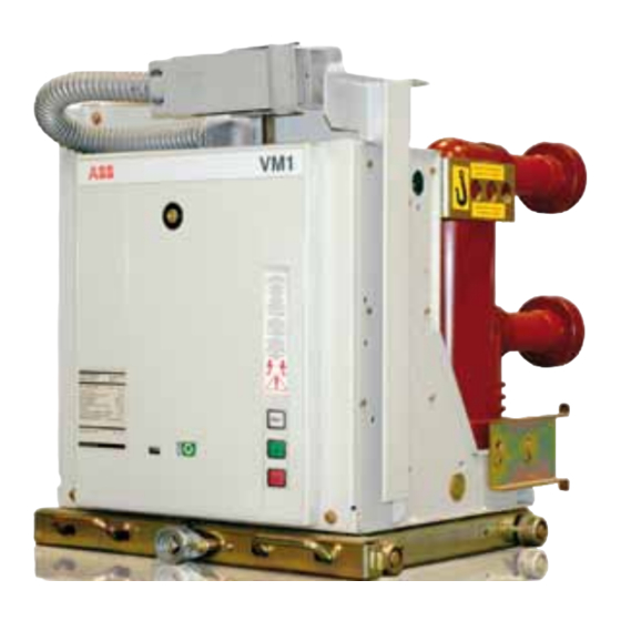
VM1/A/P
Installation and service instructions
ANSI: ... 15 kV; ... 1200 A; ... 31.5 kA
6.5. General characteristics of withdrawable
circuit-breakers for PowerCube modules
1
2
2
2
3
3
3
3
4
4
4
5
5
6
6
7
8
9
9
10
14
14
14
15
16
16
16
17
17
18
18
18
20
21
22
23
23
24
25
26
28
28
28
29
29
29
29
30
30
31
32
33
33
33
34
34
34
35
35
36
36
37
37
38
38
39
39
40
41
42
Table of Contents

Related Manuals for ABB VM1


Summary of Contents for ABB VM1
-
Page 1: Table Of Contents
6.1. Basic structure of the withdrawable circuit-breaker 8. Maintenance 6.2. Circuit-breaker structure of the circuit-breaker 8.1. General 6.3. Drive structure 8.2. Maintenance on VM1/A/P circuit-breakers 6.4. Structure of the control module 8.3. Operating life 6.5. General characteristics of withdrawable 8.4. Procedure for discharging the capacitor/s circuit-breakers for PowerCube modules 8.5. -
Page 3: For Your Safety
For your safety! • Make sure that the installation room (spaces, divisions and ambient) is suitable for the electrical apparatus. • Check that all the installation, putting into service and maintenance operations are carried out by qualified personnel with suitable knowledge of the apparatus. • Make sure that the standard and legal prescriptions are complied with during installation, putting into service and maintenance, so that installations according to the rules of good working practice and safety in the work place are constructed. • Strictly follow the information given in this instruction manual. • Check that the rated performance of the apparatus is not exceeded during service. • Check that the personnel operating the apparatus have this instruction manual to hand as well as the necessary information for correct intervention. • Pay special attention to the notes indicated in the manual by the following symbol: waRning ReSPonSible behaviouR SafeguaRdS youR own and otheRS’ Safety! foR any RequeStS, PleaSe ContaCt the abb aSSiStanCe SeRviCe. -
Page 4: Foreword
1.2. Environmental protection programme coordination studies, etc.), especially regarding any variants requested in relation to the standardised configurations. The VM1 circuit-breakers are manufactured in accordance For example, the racking and interlock sections do not apply with the ISO 14000 Standards (Guidelines for environmental to the fixed mount breaker styles. -
Page 5: Drawout
One of the physical properties of vacuum insulation is the supports. It is intended for use in ABB PowerCube modules. possibility of X-ray emission when the interrupter contacts are It contains primary and secondary disconnects and provides open. -
Page 6: Introduction And Safe Practices
/ high speed mechanisms. The design includes several for VM1/A/P vacuum circuit-breaker. This manual should be interlocks and safety features which help ensure safe and carefully read and used as a guide during installation, initial proper operating sequences. -
Page 7: Standard And Regulations
2.3. Standards and regulations 2.4. Service conditions 2.3.1. fabrication Normal service conditions The VM1/A/P circuit-breakers conform to the following Follow the recommendations in the IEC 60694 and 62271- Standards: 100 Standards. In more detail: • DIN VDE 0670, part 104, and IEC 62271-100 IEEE C37.09... -
Page 8: Reveiving, Handling, And Storage
Should any damage or irregularity be noted in the supply Immediately upon receipt of the circuit-breaker(s), examine on unpacking, notify ABB (directly or through the agent or the carton(s) to determine if any damage or loss was supplier) as soon as possible and in any case within five days sustained during transit. -
Page 9: Handling
3.2. Handling lifting hook The lifting hook is designed for general lifting and lowering VM1/A/P circuit-breaker shipping containers are designed to of the device, such as for removal from shipping pallets or be handled by fork lift (not supplied). for lifting onto and off work tables. The lifting hook is not... -
Page 10: Storage
Before carrying out any operations, always make sure that the Circuit-breakers should be installed in their permanent capacitors are discharged. location as soon as possible. If the circuit-breakers are not To lift and handle the circuit-breaker, proceed as follows (Fig. 2c): placed in service for some time, it is advisable to provide –... -
Page 11: Insertion And Removal, Putting Into Service
4. Insertion and removal, putting into service insertion: from Withdrawn position Preliminary operations Clean the insulating parts with clean dry cloths. 1. Align the circuit-breaker and ramp, dolly or lift truck with Check that the top and bottom terminals are clean and free of the compartment (Fig. -
Page 12: Putting Into Service
Opening can be carried out remotely by means of the control abb PeRSonnel oR by Suitably qualified system, or locally by pressing the “O” pushbutton on the front CuStoMeR PeRSonnel with in-dePth of the circuit-breaker within 60 s from the power failure. knowledge of the aPPaRatuS and of the inStallation. Should the oPeRationS be... - Page 13 4.2.3. operations before putting into service – check that there is a sufficient exchange of air in the Before putting the circuit-breaker into service, carry out the installation place to avoid overtemperatures; following operations: – supply the auxiliary circuits with power; – remove the lifting hooks; –...
- Page 14 4.2.4. Structure and function Summary of racking data table 2. Summary Racking data diSConneCt ConneCt Distance from Disconnected 0 mm / 0 revolutions / 0 inches 200 mm / 20 revolutions / 7.89 inches Manual opening Not recommended unless necessary Electrical Operation Yes, while power cord is connect Yes, while power cord is connect Control Power Available Yes, while power cord is connect Shutter...
- Page 15 truck This process will expose surfaces inside the truck that need The truck requires visual inspection of hardware, lubrication, to be inspected and lubricated. Lubricate the exposed parts; and operation during routine maintenance. specifically the entire Racking Screw (4. Inspect the circuit- With the circuit-breaker outside the cell, verify all visible breaker locking tabs (3) for any damage.
-
Page 16: Installation
5. Installation 5.1. General waRning CoRReCt inStallation iS of PRiMe iMPoRtanCe. the ManufaCtuReR’S inStRuCtionS MuSt be CaRefully Studied and followed. it iS good PRaCtiCe to uSe gloveS to handle the PieCeS duRing inStallation. the aReaS involved by the PaSSage of PoweR ConduCtoRS oR ConduCtoRS of auxiliaRy CiRCuitS MuSt be PRoteCted againSt aCCeSS of any aniMalS whiCh Might CauSe daMage oR diSSeRviCeS. 5.2. Trip curves Caption The following graphs show the number of closing-opening cycles (No.) allowed, of the vacuum interrupters, according to nr. Number of closing-opening cycles allowed for the vacuum interrupters. Breaking capacity of the vacuum interrupters. -
Page 17: Interlocks/Protection Against Malfunction
5.3. Interlocks/protection against interlocks The VM1/A/P circuit-breaker contains a number of interlocks. malfunction A description of each interlock follows as encountered during A series of interlocks is provided to prevent incorrect racking of the circuit-breaker into the compartment. operations and/or malfunctions. The interlocks are the following: •... -
Page 18: Racking
5.4. Racking 5.5. Disconnect through connect VM1/A/P circuit-breakers are designed with two positive 1. Perform a visual inspection of the circuit-breaker: racking positions: Disconnect, Connect. In the Disconnect a. Verify Close/Open Indicator shows OPEN. position the shutters are closed. Electrical closing from the b. -
Page 19: Connect Through Disconnect Emergency Rack Out
5.7. Connect through disconnect 5.8. Installation of withdrawable circuit- emergency rack out (Fig. 9) breakers 1. In the case of a locking magnet –RL2 fault, in an The withdrawable circuit-breakers are preset for use in Vesta emergency the truck can be racked out manually following switchgear or PowerCube modules. -
Page 20: Description
Description 6.1. Basic structure of the withdrawable 6.2. Circuit-breaker structure of the circuit-breaker (Fig.10a) circuit-breaker (Fig.10b) The withdrawable truck (9), consists of a steel sheet structure The encapsulated poles are installed on the rear flat section of with wheels (3), on which the circuit-breaker with the relative the circuit-breaker frame (1.1. - Page 21 1 Top terminal 8a Kinematics for transmission of the drive movement to the circuit-breaker poles 2 Vacuum interrupter 9 Run regulator 2a Fixed contact 10 Position sensors 2b Moving contact 11 Closing coil 3 Pole 12 Permanent magnets 4 Bottom terminal 13 Moving armature 5 Flexible connection 14 Opening coil...
-
Page 22: Drive Structure
6.3. Drive structure • closing pushbutton “I” (8) • opening pushbutton “O” (9) The drive is of the magnetic type and basically consists of • coupling for manual emergency operation (1) the magnetic actuator (6) (Fig. 11), the control module (5), the •... -
Page 23: Structure Of The Control Module
6.4. Structure of the control module The energy available in relation to the relevant switch position is the criteria which determines The control module consists of a single circuit board. This board contains a series of components: • Case 1: Circuit-breaker in the OPEN position •... -
Page 24: General Characteristics Of Withdrawable Circuit-Breakers For Powercube Modules
[°C] -30 ... +40 IEC: 60068-2-30 • Tropicalization 721-2-1 • Electromagnetic compatibility IEC 60694 • 1) Rated uninterrupted currents guaranteed with withdrawable circuit-breaker installed with air temperature of 40°C. 2) Only VM1/A/P 15.12.32 can leave (on request) UL type L liasted sticker. -
Page 25: Types Of Withdrawable Circuit-Breakers Available For Powercube Modules
ø = 35 a. Wait until “READY” lamp is on; approximately two minute PowerCube maximum depending on control voltage with 48 V DC 1250 VM1/A/P 15.12.25 p150 taking the longest amount of time. 31.5 1250 VM1/A/P 15.12.32 p150 b. Circuit-breaker is ready to perform C-O operation. -
Page 26: Control Scheme
The capacitor voltage will vary 5 to 10Vdc during switching operations allowing for fast recharge and reclose schemes. VM1/A/P circuit-breakers are similar in switching con-trol to The opening and closing coils are operated via the storage standard spring stored energy mechanisms as indicated by capacitor(s) and thus only require a minimal signal (24V min) the Sequence of Operation in Chart 1. -
Page 27: Standard Fittings
(only for ABB UniGear type switchgear). 10) racking-in/out lever (the quantity must be defined... -
Page 28: Optional Accessories
6.10. Optional accessories 2) binary inputs (logical inputs) for remote control: – N. 1 input for closing command (-SC2) (top logical input The accessories identified by the same number are alternative activated) to each other. – N. 1 input for opening command (-SO2) (top logical input activated) 1 ed2.0 Control module –... - Page 29 (installed in the circuit-breaker truck - only for withdrawable – limitation of the feeder connection current circuit-breaker for UniGear ZS1 switchgear and for – serial RS232 for local connection (only to be used by ABB PowerCube enclosure). personnel). These contacts are either in addition or as an alternative to the position contacts (for signalling circuit-breaker racked- n.b. Some of the control module functions can be excluded/set by means...
-
Page 30: Operation
All the conditions for control of the magnetic actuator (Refer to figure 10b) mechanism are defined in a permanently programmed logic The magnetic actuator used in the VM1/A/P circuit-breaker module. These conditions are: generates the run required to operate the moving contacts of •... -
Page 31: Opening And Closing Procedure
7.3. Opening and closing procedure • de-activation of the opening or closing coil takes place when the relative limit position has been reached. (Refer to figure 10) • WRONG POSITION (auto trip) function: if the final CLOSED The opening and closing processes are initiated either by (or OPEN) position is not reached within 70 ms during a remote control via closing contacts or locally by manual closing (or opening) operation, an opening operation is... -
Page 32: Ready" Signalling
7.7. “READY” signalling 7.8. Truck locking magnet (compulsory device) The luminous signal and relative “READY/NOT READY” contacts signal: The locking magnet is inserted in withdrawable circuit- • capacitor/s charged breakers with manual movement and prevents traverse of the • detection of the correct “CLOSED” and “OPEN” positions withdrawable truck when there is no power supply voltage. -
Page 33: Circuit-Breaker Control Card
- luminous “READY” signal undervoltage input (the circuit-breaker re-opens after the set on off delay time) Selector not used for the VM1 circuit-breaker (the position selected does not matter) Operating time setting Connector for input signal of I1002-2 "off" & JP1017... -
Page 34: Characteristics Of The Control Module Contacts Without Potential
7.10. Characteristics of the 0 ... 264 V~ 50/60 Hz Rated voltage (operating range) control module contacts 0 ... 280 V– 1500 VA (V a.c. on resistive load) Maximum power applicable without potential (see curves B and C) (V d.c. on resistive load - curve A) 400 V~ 50/60 Hz Maximum voltage applicable The contacts without potential are supplied with... -
Page 35: Maintenance
– regulations for safety in the workplace indicated in the “Putting into service and operations” chapter; – regulations and specifications of the country where the apparatus is installed. VM1/A/P circuit-breakers are designed for a minimum amount The maintenance operations can only be carried out by of maintenance. Circuit-breakers in a clean, non-corrosive trained personnel who respect all the safety regulations. -
Page 36: Operating Life
Remove the front cover by unfastening its screws and Typical useful life expectancy of a VM1 vacuum circuit-breaker correct any loose or missing hardware. is determined by the following factors: Always lubricate the working surface of the moving parts. -
Page 37: Inspections And Functional Tests Interruption Device In General
• insulate the working area and make it safe by following the Note These operations can only be carried out by ABB personnel or suitably qualified safety regulations specified in the IEC/DIN VDE Standards. and specially trained personnel. -
Page 38: Circuit-Breaker Pole
All power supply sources must be disconnected and made safe against any reclosing during removal and installation note work. Dismantling and replacement of the pole can only be carried out by ABB personnel or suitably qualified and specially trained personnel, especially for the necessary adjustments. Caution... -
Page 39: Control Wiring
DO NOT return the circuit-breaker into service until the 15 kV 36 kV 27 kV insulation surfaces are completely dry . Lubrication on the primary contacts should be inspected table 3: Primary low-frequency withstand test voltage during routine maintenance. Use only grease ISOFLEX TOPAS NB52 (ABB GCE0007249P01001PLCRN). -
Page 40: Maintenance
Maintenance 9.1. Vacuum interrupters dangeR To verify the integrity of the vacuum interrupters perform the following low-frequency withstand voltage test: 1. Open the circuit-breaker (no control power supplied to the circuit-breaker). a. Connect the high potential lead to one terminal. b. -
Page 41: Spare Parts And Accessories
– Position contact of the withdrawable truck – Contacts signalling racked-in/isolated – Isolation interlock with the door – Locking electromagnet on the withdrawable truck – Set of six tulip contacts. all aSSeMbly oPeRationS of SPaRe PaRtS/aCCeSSoRieS MuSt be CaRRied out following the inStRuCtionS enCloSed with the SPaRe PaRtS, by abb PeRSonnel oR by Suitably qualified CuStoMeR PeRSonnel with in-dePth knowledge of the aPPaRatuS (ieC 60694) and all the StandaRdS aiMed at CaRRying out theSe inteRventionS in Safe ConditionS. Should the MaintenanCe be CaRRied out by the CuStoMeR’S PeRSonnel, ReSPonSibility foR the inteRventionS ReMainS with the CuStoMeR. -
Page 42: Product Quality And Environmental Protection
9001 and by the EMS according to ISO 14 001. End of life of product The ABB company is committed to complying with the relevant legal and other requirements for environment protection according to the ISO 14 001 standard. The duty of company is to facilitate subsequent recycling or disposal at the end of product life. During disposal of the product, it is always necessary to act in accordance with local legal requirements in force. -
Page 43: Overall Dimensions
12. Overall dimensions VM1/A/P - 1VDC003606 492 19,37 121 4,76 26 1,03 233 9,17 43 1,69 36 1,42 303 11,92 71 2,80 25 0,98 320 12,60 192 7,55 370 14,57 101 3,96 383 15,08 340 13,39 416 16,39 503 19,80... -
Page 44: Electric Circuit Diagram
13. Electric circuit diagram Circuit-diagram of VM1/P-W-Z-ZH circuit-breaker in The diagram indicates the following conditions: withdrawable version with magnetic actuator. – circuit-breaker off and connected For other circuit-breakers, please consult us. – circuits de-energized graphical symbols for electrical diagrams (617 ieC Standards) Thermal effect Conductors in screened... - Page 51 Caption -SC 1 = Pushbutton for the circuit-breaker local closing = Reference number of diagram figure -SO1 = Pushbutton for the circuit-breaker local opening = See note indicated by the letter -RD1 = Diode = Circuit breaker accessories -RL2 = Truck locking m agnet = Control and switching unit -SC2 = Pushbutton or contact for the circuit-breaker...
- Page 52 ED2 with or without auxiliary contacts D) The circuit-breaker is delivered complete with the (-BB1, -BB2) accessories listed in the ABB SACE PTMV order acknow Fig. 6 = Inputs/Outputs for circuit-breaker with full- ledgement only. To draw up the order examine the options ED2 with or without auxiliary contacts apparatus catalogue.
- Page 53 Notes...
- Page 54 Notes...
- Page 56 For more information please contact: Your sales contact: www.abb.com/contacts More product information: www.abb.com/productguide The data and illustrations are not binding. We reserve the right to make changes without notice in the course of technical development of the product. © Copyright 2011 ABB.