Table of Contents
Quick Links
See also:
Instruction Manual
Table of Contents

Related Manuals for Emerson FLOBOSS S600


Summary of Contents for Emerson FLOBOSS S600
- Page 1 Form A6115 Part Number D301150X412 September 2004 FLOBOSS™ S600 Flow Manager Instruction Manual Flow Computer Division Website: www.EmersonProcess.com/flow...
- Page 2 All Pages 8/01 FloBoss and ROCLINK are marks of one of the Emerson Process Management companies. The Emerson logo is a trademark and service mark of Emerson Electric Co. All other marks are the property of their respective owners. © Fisher Controls International, LLC. 2001-2004. All rights reserved.
-
Page 3: Table Of Contents
5.10 Using the Exponential Key......................5-8 5.11 Using the Print Key ........................5-9 SECTION 6 – WEB SERVER ACCESS................... 6-1 6.1 How to Access the FloBoss S600....................6-1 6.2 How to Navigate the Web Server Interface................6-2 SECTION 7 – STARTUP ........................7-1 7.1 Starting the FloBoss S600 ...................... - Page 4 FloBoss S600 Instruction Manual 7.3 Cold Start ...........................7-1 7.4 Startup Menu..........................7-3 7.5 Network Setup ...........................7-3 SECTION 8 – TROUBLESHOOTING .....................8-1 8.1 Troubleshooting Guidelines.......................8-1 8.2 Troubleshooting Checklists .......................8-1 8.3 Procedures..........................8-3 APPENDIX A – FRONT PANEL NAVIGATION ................A-1 A.1 Main Menu..........................A-1 A.2 Flow Rates Menu ........................A-2 A.3 Totals Menu ..........................A-3...
-
Page 5: Section 1 - General Information
♦ Section 6 – Web Server Access shows how to access the FloBoss S600 through a web server interface. This includes screen displays and interface navigation basics. -
Page 6: Floboss S600 Flow Computer
The FloBoss S600 Flow Manager is designed for use either as a stand-alone flow computer or as a system component. The intelligent I/O boards fit both gas and liquid applications and support two streams and a header. - Page 7 ♦ One dedicated configuration port for connection to the Config 600 Software. The FloBoss S600 uses distributed processing to achieve maximum performance. The main CPU incorporates a hardware floating point processor. Each additional card also has local processing to convert inputs and output from engineering units to field values and vice-versa, as well as running background tests and PID loops.
- Page 8 Config 600 Pro software interface. The IPL600, Config 600 Lite and Config 600 Pro interfaces allow both sending (download) of new or modified configurations and receiving (upload) of existing configuration from the FloBoss S600. The front panel interface consists of a backlit LCD display, 29-button keypad, and an alarm status LED.
-
Page 9: Config 600 Software
VxWorks firmware and receives and sends configurations. In Config Lite and Config Pro, this interface is referred to as the Transfer Editor. NOTE: The FloBoss S600 will not operate until a configuration has been sent from the host PC. 1.3.2 Config 600 Lite The Config 600 Lite editors can be used to modify pre-developed configurations, transfer configurations, edit items on the front panel display, and edit report formats. - Page 10 FloBoss S600 Instruction Manual ♦ Edit process configuration data, including orifice size, analog input scaling, alarm limits, and keypad values. ♦ Build and customize Modbus slave maps, Modbus master polling sequences, front panel displays, and period report formats. ♦ Specify the engineering units and totalization rollover value.
-
Page 11: Floboss S600 Specifications
FloBoss S600 Instruction Manual 1.4 FloBoss S600 Specifications Specifications I/O CAPABILITY POWER REQUIREMENTS Analog Inputs: 0 to 5.2 V dc or 0 to 22 mA, >16 Supply Voltage: 20-32 V dc, 24 W (nominal). bits. Protection: 2.5 A Anti-surge fuse. -
Page 12: Section 2 - Installation
Although the FloBoss S600 shipped to you may not include all of the hardware options described in this manual, the procedure for the basic installation of the unit remains the same. -
Page 13: Environmental Considerations
Figure 2-1. FloBoss S600 System Components 2.2 Environmental Considerations The FloBoss S600 panel mount is designed for use within the control room and should be placed in a position that provides ease of use, comfort, and safety for operators and maintenance personnel. The optimum height for viewing and using the display and keypad is at operator eye level. -
Page 14: Installing The Floboss S600
Figure 2-2. Removing the Front Panel Carefully slide the FloBoss S600 face up 4 mm (0.15 in) to allow it to clear the retaining groove at the top of the case, and then allow the face to come forwards to clear the panel case completely. - Page 15 Figure 2-4. Observe the orientation of the connector with its mating keyway. The ribbon cable must be correctly re-inserted at the end of the installation process. Do not remove the ribbon cable from the FloBoss S600 housing entrance. This might cause damage to the unit.
- Page 16 Refer to Figure 2-6 and Table 2-1 for position details for two 7 mm (0.276 in.) holes and a cutout. The panel cut out should be rectangular in shape for each FloBoss S600 unit. A tolerance of +/- 3 mm (0.12 in.) is allowed on each axis.
- Page 17 FloBoss S600 Instruction Manual Figure 2-6. Panel Cutout Dimensions Panel thickness should be at least 3 mm (0.12 in) to prevent distortion. Thinner panels can be used, but these require the rear of the case to be supported. Refer to Figure 2-7.
-
Page 18: Installation And Removal Of The Boards
2.4.4 Re-installing the Front Panel The final stage of the installation process is to re-install the front panel on the FloBoss S600 as follows: Connect the ribbon cable (from the front of the case) to the connector on the front panel. - Page 19 FloBoss S600 Instruction Manual Figure 2-8. Unscrewing the Retention Screws Unlatch the pull-tabs for the appropriate board and pull the board clear of the case. Some rocking of the board may be required to release the connector. Refer to Figure 2-9 and Figure 2-10.
- Page 20 FloBoss S600 Instruction Manual Figure 2-10. Board Ready for Removal or Final Insertion To install the plug-in boards: Install the plug-in boards with care by aligning them in the guides (located at top and bottom of the case). Gently slide the board until it mates fully with the appropriate connector on the backplane.
-
Page 21: Section 3 - Cpu
AWG. All local wiring practices and regulations should be observed. Do not use a Megger or similar instrument to check for isolation or continuity between signals on any of the connectors of the FloBoss S600. These instruments produce voltages far in excess of design parameters and damage may occur. -
Page 22: Power Supply
FloBoss S600 Instruction Manual P152 CPU NETWORK SERVICE SERVICE RJ45 TB - 1 + VE 24V DC SUPPLY + 24v ETHERNET + 15v COMPUTER ALARM COMM - 4 SERVICE RJ45 SIG GND REMOTE I/O SERVICE '9' D FEMALE TX +... - Page 23 FloBoss S600 Instruction Manual The FloBoss S600 should be powered by a nominal 24 volts dc power source capable of supplying 2 Amps. The unit will operate between 20 and 32 volts dc. The startup in-rush current may draw 6 Amps for approximately 100 milliseconds. This in-rush becomes significant when multiple flow computers are connected to the same power supply.
-
Page 24: Communication Ports
3.3 Communication Ports The FloBoss S600 CPU has nine standard communication ports (eight serial and one Ethernet). The following table details the communications ports. Comm Ports 1 and 8 contain internal connections to other boards in the FloBoss S600 NOTE: which are not available for external host or local operator communications. - Page 25 FloBoss S600 Instruction Manual 3.3.1 EIA-232 (RS-232) Serial Port Two EIA-232 (RS-232D) communications ports are provided on the backplate of the P152 CPU board. The ports use FCC-68 RJ-45 connectors and are labeled COM3 and COM4. The COM3 and COM4 pin connections are shown in Table 3-5.
- Page 26 FloBoss S600 Instruction Manual 3.3.2 EIA-422 (RS-422)/EIA-485 (RS-485) Multi-drop Port Three EIA-422 (RS-422) or EIA-485 (RS-485) ports are located on the backplate of the P152 CPU board and provide high speed/long distance links of up to 38400 bps and 1200 m (4000 ft). The ports use the connector labeled TB-2, which is COM5, COM6, and COM7.
- Page 27 CTS to PC 3.3.4.1 Connecting to the FloBoss S600 A special serial cable is required to connect the host PC to the FloBoss S600 unit. A ready-made link cable is available for a PC with a 9-pin serial port. Alternatively, you may fabricate your own link cable using the wiring details in Figure 3-4.
-
Page 28: Cpu On-Board Connectors
FloBoss S600 Instruction Manual Figure 3-4. Link Cable 3.4 CPU On-Board Connectors The miscellaneous device connectors provided on the P152 CPU module are shown in Table 3-8. This information is for identification purposes only. Do not modify these connections, unless told to do so by the factory. - Page 29 FloBoss S600 Instruction Manual Table 3-9. CPU Bit Links Jumper (Link) Position Description LK1 & LK2 Not Used CPU & RADISYS ON/OFF Voltage Selection (On = 5 V, Off = 3.3 V) ON/OFF Internal Real Time Clock enable ON/OFF Internal keyboard & mouse disable...
-
Page 30: Dual Ethernet Lan Port
FloBoss S600 Instruction Manual 3.6 Dual Ethernet LAN Port The optional P190 second Ethernet port on the FloBoss S600 is for high-speed communications using an Ethernet Local Area Network (LAN) architecture. The speed of data transfer is 10M bps when using 10BaseT twisted pair cable. -
Page 31: Section 4 - I/O
Do not use a Megger or similar instrument to check for isolation or continuity between signals on any of the connectors of the FloBoss S600. These instruments produce voltages far in excess of design parameters and damage may occur. - Page 32 FloBoss S600 Instruction Manual P144 IIO 1 SERVICE SERVICE SKT A SKT A +15V ADC 1+ SUPPLY ADC 2+ DAC 1 OUTPUT ADC 3+ GROUND +15V 1 - 5 V ADC 4+ SUPPLY ADC 5+ DAC 2 OUTPUT LK16-20 GROUND...
-
Page 33: Analog Inputs
FloBoss S600 Instruction Manual 4.1.1 Analog Inputs There are two fully floating A/D converters per I/O board, each measuring five single-ended Analog Input (ANIN) channels. Each channel (ANIN 1-10) is configurable as a 0 to 5.25 volt or 0 to 22 mAmp input range. -
Page 34: Analog Outputs
The D/A Converter output channels use the connector labeled SKT-A, which is located on the backplate of the P144 board. The D/A Converter output pin connections on the back of the I/O card are shown in Table 4-3. Figure 4-5. Analog Output Schematic (FloBoss S600 Powered) Rev Sep/04... - Page 35 FloBoss S600 Instruction Manual Figure 4-6. Analog Output Schematic (Externally Powered Device) Figure 4-7. Analog Output Schematic (Externally Powered through FloBoss S600) Table 4-3. D/A Converter Output Pin Connections for SKT-A Function DAC-CH1 +15 V SOURCE DAC-CH1 SINK DAC-CH1 0 VDC...
- Page 36 FloBoss S600 Instruction Manual 4.1.3 Digital Inputs There are 16 optically-isolated Digital Inputs (DIGIN) per plug-in board. The digital inputs have been grouped into four banks of 4-off single ended inputs with one common feed. Refer to Figure 4-8 and Figure 4-9.
- Page 37 FloBoss S600 Instruction Manual Table 4-4. DIGIN Pin Connections for SKT-B Function DIGIN-CH1 DIGIN-CH2 DIGIN-CH3 DIGIN-CH4 RETURN CH1-4 DIGIN-CH5 DIGIN-CH6 Table 4-5. DIGIN Pin Connections for SKT-C Function DIGIN-CH7 DIGIN-CH8 RETURN CH5-8 DIGIN-CH9 DIGIN-CH10 DIGIN-CH11 DIGIN-CH12 RETURN CH9-12 DIGIN-CH13 DIGIN-CH14...
- Page 38 FloBoss S600 Instruction Manual 4.1.4 Digital Outputs There are 12 digital output channels. The digital outputs (DIGOUT) are open collector type. The maximum current rating is 100 mAmps at 24 volts dc. Output frequencies up to 0.5 Hz are possible.
- Page 39 FloBoss S600 Instruction Manual Table 4-7. DIGOUT Pin Connections for SKT-C Function DIGOUT-CH3 DIGOUT-CH4 RETURN CH1-4 DIGOUT-CH5 DIGOUT-CH6 DIGOUT-CH7 DIGOUT-CH8 RETURN CH5-8 DIGOUT-CH9 DIGOUT-CH10 DIGOUT-CH11 DIGOUT-CH12 RETURN CH9-12 4.1.5 Turbine Pulse Inputs When the optional Mezzanine card for Pulse Inputs (P148) is installed on the P144 I/O board, four Pulse Inputs may be used either independently or in pairs of two.
- Page 40 FloBoss S600 Instruction Manual Figure 4-13. Pulse Input Schematic (using US 24 V P148 Mezzanine Card) Table 4-8. Dual-Pulse Input Pin Connections for SKT-C Function SINGLE/DUAL PULSE-CH1+ SINGLE/DUAL PULSE-CH1- SINGLE/DUAL PULSE-CH2+ SINGLE/DUAL PULSE-CH2- SINGLE/DUAL PULSE-CH3+ SINGLE/DUAL PULSE-CH3- SINGLE/DUAL PULSE-CH4+ SINGLE/DUAL PULSE-CH4- 4.1.6 Pulse Outputs...
- Page 41 FloBoss S600 Instruction Manual Table 4-9. PULSEOUT Pin Connections for SKT-B Function PULSEOUT-CH1 PULSEOUT-CH2 PULSEOUT-CH3 PULSEOUT-CH4 RETURN CH1-4 PULSEOUT-CH5 RETURN CH5 4.1.7 Raw Pulse Output There is a single raw pulse output, typically used in prover applications to mimic the turbine signals and send them to the prover mezzanine card.
- Page 42 FloBoss S600 Instruction Manual Table 4-10. Raw Pulse Output Pin Connections for SKT-C Function Raw Output Return 4.1.8 Frequency Inputs The three Frequency Inputs are typically used for density transducer signals. Each input has an input range of 0 to 10 KHz. Bit links are provided to allow the inputs to be AC or DC coupled. Refer to Figure 4-16 and Figure 4-17.
- Page 43 FloBoss S600 Instruction Manual Table 4-11. Frequency Input Pin Connections for SKT-B Function FREQUENCY-CH1+ FREQUENCY-CH1- FREQUENCY-CH2+ FREQUENCY-CH2- FREQUENCY-CH3+ FREQUENCY-CH3- 4.1.9 PRT/RTD Inputs There are three Platinum Resistance Thermometer (PRT)/Resistance Temperature Detector (RTD) inputs. The PRT/RTD inputs are suitable for Class A, 4-wire PRT devices that conform to the BS EN 60751:1996 standard.
- Page 44 FloBoss S600 Instruction Manual Table 4-12. PRT Input Pin Connections for SKT-B Function PRT-CH1 I+ PRT-CH1 V+ PRT-CH1 V- PRT-CH1 I- PRT-CH2 I+ PRT-CH2 V+ PRT-CH2 V- PRT-CH2 I- PRT-CH3 I+ PRT-CH3 V+ PRT-CH3 V- PRT-CH3 I- 4.1.10 P144 I/O Bit Links (Jumpers) The entries shown in boldface are the default configuration settings;...
- Page 45 FloBoss S600 Instruction Manual Table 4-13. P144 I/O Bit Link Settings Bit Link Position Description Flash Write Enable Flash Write Protected Point to Point mode enabled Point to Point mode off LK3 - LK10 Multiplex (MUX) Addresses – See table below...
- Page 46 FloBoss S600 Instruction Manual Table 4-14. Multiplex Mode Addressing Address LK3 LK10 COMMENT Not a Valid address or only board Board Not a Valid address Rev Sep/04 4-16...
- Page 47 FloBoss S600 Instruction Manual 4.2 P154 Prover Board The P154 dedicated prover interface card has been designed to work with compact or microprover, unidirectional and bi-directional provers, with 2 or 4 detector switches. In addition, it contains high resolution timing circuits so that dual chronometry methods can be utilized to increase the apparent resolution for instances when insufficient turbine pulses are present with the prover volume available.
- Page 48 FloBoss S600 Instruction Manual P154 IIO 2 SERVICE SERVICE SKT D SKT D SWITCH 1 - RAW PULSE + SWITCH 2 - INPUT 1 - RAW PULSE + SWITCH 3 - INPUT 2 - SWITCH 4 - RAW PULSE +...
- Page 49 FloBoss S600 Instruction Manual 4.2.1 Digital Inputs There are 32 optically-isolated Digital Inputs (DIGIN) per plug-in board. The digital inputs have been grouped into four banks of 4-off single ended inputs with one common feed. The sample period is 500 milliseconds.
- Page 50 FloBoss S600 Instruction Manual Table 4-16. DIGIN Pin Connections for SKT-F Function DIGIN-CH7 DIGIN-CH8 RETURN CH5-8 DIGIN-CH9 DIGIN-CH10 DIGIN-CH11 DIGIN-CH12 RETURN CH9-12 DIGIN-CH13 DIGIN-CH14 DIGIN-CH15 DIGIN-CH16 RETURN CH13-16 4.2.2 Digital Outputs There are 12 digital output channels. The digital outputs (DIGOUT) are high current, open collector type.
- Page 51 FloBoss S600 Instruction Manual Table 4-18. DIGOUT Pin Connections for SKT-F Function DIGOUT-CH3 DIGOUT-CH4 RETURN CH1-4 DIGOUT-CH5 DIGOUT-CH6 DIGOUT-CH7 DIGOUT-CH8 RETURN CH5-8 DIGOUT-CH9 DIGOUT-CH10 DIGOUT-CH11 DIGOUT-CH12 RETURN CH9-12 4.2.3 Turbine Pulse Inputs The four Pulse Inputs may be used either independently or in pairs of two. Generally, they are used for dual pulse measurement, such as turbine applications.
- Page 52 FloBoss S600 Instruction Manual Table 4-20. PULSEOUT Pin Connections for SKT-E Function PULSEOUT-CH1 PULSEOUT-CH2 PULSEOUT-CH3 PULSEOUT-CH4 RETURN CH1-4 4.2.5 Frequency Inputs There are two Frequency Inputs, typically used for density transducer signals. Each input has an input range of 0 to 10 KHz.
- Page 53 FloBoss S600 Instruction Manual 4.2.6 P154 Prover Bit Links (Jumpers) The entries shown in boldface are the default configuration settings; these may not apply to your specific configuration. Table 4-22. P154 Prover Bit Links (Jumpers) Link Position Descriptions Flash Write Enable...
-
Page 54: P188 Hart Board
FloBoss S600 Instruction Manual 4.3 P188 HART Board HART communication is facilitated by way of a 12 channel I/O board. Each digital input channel is capable of handling up to 8 devices (up to 50 Transmitters in total). Point to point and multi-drop architectures are supported. - Page 55 FloBoss S600 Instruction Manual Figure 4-21. HART Device Beyond the IS Barrier Figure 4-22. HART Device and Hand Held Communicator Beyond the IS Barrier Rev Sep/04 4-25...
- Page 56 FloBoss S600 Instruction Manual Figure 4-23. HART Device without Hand Held Communicator Rev Sep/04 4-26...
-
Page 57: Section 5 - Front Panel
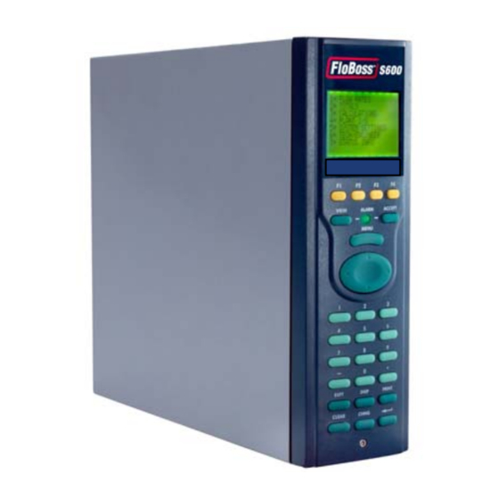
5.1 Description The front panel of the FloBoss S600 provides a local interface so that the user may view or make changes to the values and status of parameters. The layout of the FloBoss S600 front panel is shown in Figure 5-1. -
Page 58: Keypad
FloBoss S600 Instruction Manual 5.2 Front Panel Port This is an alternative connection for PC communications (Comm 2) and is used with the CONFIG 600 program to transfer configuration files. The port is located on the underside (bottom) of the front panel. It requires a six pin RJ-12 connector for EIA-232 (RS-232D) communications. -
Page 59: Alarm Led And Alarm Keys
♦ Numeric 0 to 9 – Used to enter or change data and to navigate the display screens. ♦ Minus – Used to define the default display on the FloBoss S600 or to enter negative numbers and the decimal point when entering fractional numbers. -
Page 60: Display
FloBoss S600 Instruction Manual Alarms can be triggered when measurements exceed the pre-set limits for a parameter or when there is a malfunction. The alarm may be relayed to a terminal or klaxon in the Control Room. On the panel of the S600, a flashing red LED indicates an alarm, and the source of the alarm can be shown on the display. -
Page 61: Navigating The Display
The Page Reference Number indicates the location of a data item on the FloBoss S600 displays. One way to understand the FloBoss S600 displays is to visualize the data items as if they were written on the exterior of a very large cylinder. The Page Reference Number calls out the column on the cylinder, followed by the row, in a “column.row”... -
Page 62: Entering Data
To enter the edit sequence: Press the Chng key. If more than one asterisk is shown on a data display, the FloBoss S600 highlights the first object on the page. Use the ▲ and ▼ keys to move the highlight to the required point. - Page 63 FloBoss S600 Instruction Manual At the prompt ENTER NEW VALUE: key in the new value in integer, numeric, or scientific notation as appropriate (the current value and any entry limits associated with this parameter are also shown). Press Enter to confirm.
-
Page 64: Assigning A Default Page
Press the desired F key (F1, F2, F3, or F4) to which the display page is to be assigned. Once programmed, an F key cannot be unassigned unless the SRAM is cleared or the FloBoss S600 is cold started. However, you can re-assign a F key to a different display page. -
Page 65: Using The Print Key
(to represent the power), and press Enter to confirm. 5.11 Using the Print Key By default the FloBoss S600 is configured to output reports to a serial printer or a terminal. The Print key is used to generate either a constant log or pre-configured reports. -
Page 66: Section 6 - Web Server Access
6.1 How to Access the FloBoss S600 If no users are currently logged on to the FloBoss S600 through the front panel display, the FloBoss S600 may be accessed by a web connection. There is always only one point of control. If a user is logged in to the web browser, you will not be able to change data from the front panel. -
Page 67: How To Navigate The Web Server Interface
FloBoss S600 Instruction Manual 6.2 How to Navigate the Web Server Interface The web browser interface allows the user to view reports and data from the front panel display screens. Navigation of the interface is acheived through two navigation bars. Elements of the database are in a menu bar at the top of the screen. - Page 68 Figure 6-3. Prover Data Menu (Prover I/O Screen Shown) Some of the screens allow the viewer to interact with the FloBoss S600 unit. If the text appears in bold, the data is changable. If the text appears in red, the object is in an alarm state. Modifications to the screen will be sent to the FloBoss S600 unit as they are made.
- Page 69 To close the web server access link, use the Log Off button in the menu bar and close the browser. NOTE: Exercise CAUTION. Due to the caching mechanism on many internet browser applications, please remember to close the browser on your PC. This will ensure the browser does not remember the FloBoss S600 details. Rev Sep/04 Web Server Access...
-
Page 70: Section 7 - Startup
For information on navigating the display screens, refer to Section 5. If a valid configuration can not be found, the FloBoss S600 will not warm start. It will instead go to the Startup menu. Please refer to Section 7.4 for details. - Page 71 7.3.1.1 No Power Applied If the FloBoss S600 is NOT powered up, you may set Bit Link LK13 on the P152 CPU board to the closed (cold start) position and then apply power to the unit. This will cause the Startup menu to appear.
-
Page 72: Startup Menu
♦ Warm Start – This selection restarts a previously configured FloBoss S600 where it left off prior to being powered down. ♦ Cold Start – This is used to build a new metering database on the FloBoss S600 using the configuration files stored in Flash memory. - Page 73 Select the Modbus Address option. Enter the address value (a maximum value of 247 is permitted). If the Modbus address has been changed, restart the FloBoss S600 for the change to take place. Before establishing an Ethernet LAN connection (for host communications, local operator communications, or web server access), you will need to verify and/or define the TCP/IP Address.
-
Page 74: Section 8 - Troubleshooting
When you are done troubleshooting, perform a warm start or cold start. Refer to Section 7. If you are instructed by your local sales representative or technical support to return the FloBoss S600 unit, replace the troubled parts with spares and return the troubled parts to the address given by the local sales representative or technical support. -
Page 75: Front Panel Led
If the LED on the Front panel indicates alarm and malfunction states: ♦ If the LED is green, then the FloBoss S600 is functioning correctly. ♦ If the LED is red, an alarm state exists. Refer to Section 5.4 for more information on Alarms. -
Page 76: Procedures
The Reflash Firmware option allows you to reprogram the Flash memory with new values for the operating system components and the application firmware. Under no circumstances should you allow the FloBoss S600 to be turned off while it is erasing or reprogramming the Flash memory. Doing so will render the FloBoss S600 unusable. - Page 77 Following a Clear SRAM command, the FloBoss S600 will restart and return to the Startup menu. The FloBoss S600 will not be able to warm start again until a full configuration is sent from a PC running Config 600 software.
- Page 78 Check the fuse and, if necessary, replace it with a 20 mm x 5 mm 2.5 Amp anti-surge fuse only. The use of a fuse with a higher current rating invalidates the warranty on the FloBoss S600. Replace the fuse and check it is secure before replacing the CPU module into the case.
-
Page 79: Appendix A - Front Panel Navigation
FloBoss S600 Instruction Manual APPENDIX A – FRONT PANEL NAVIGATION This section describes the default menu options of the FloBoss S600 front panel display. The layout and navigation basics of the FloBoss S600 front panel are described in Section 6. -
Page 80: Flow Rates Menu
FloBoss S600 Instruction Manual A.2 Flow Rates Menu The parameters in this group are all used in calculating the various flow rates. If one of the streams is a prover, the stream will not appear on this menu. Main > Flow Rates Menu... -
Page 81: Totals Menu
FloBoss S600 Instruction Manual A.3 Totals Menu The parameters in this group are all used in calculating the various totals. If one of the streams is a prover, the stream will not appear on this menu. Main > Totals Menu... -
Page 82: Operator Menu
3. STR02 FWD PREM 4. STR02 REV PREM A.4 Operator Menu The parameters in this group are values and statuses the user will generally wish to view when monitoring the operation of the FloBoss S600. Main > Operator Menu 1* Station 1... - Page 83 FloBoss S600 Instruction Manual Operator Submenus (Options 1-6) Station 1 (Gas EU) Station 2 (Liquid EU) Stream 1 (Gas Turbine) Stream 2 (Gas DP) Stream 3 (Liquid Stream 4 (Prover Ball) Coriolis) 1. MOLES 1. AVE T&P 1. COMPOSITION 1. COMPOSITION 1.
-
Page 84: Plant I/O Menu
FloBoss S600 Instruction Manual A.5 Plant I/O Menu The parameters in this group are the values, limits and status of the field I/O. Main > Plant I/O Menu 1* Analog Inputs 2* PRT/RTD Inputs 3* Frequency Inputs 4* Pulse Inputs... - Page 85 FloBoss S600 Instruction Manual 4. ADC 16 – ADC04 5. ADC 17 – ADC05 6. ADC 18 – ADC 06 7. ADC 19 – ADC 07 8 NEXT 1 PREVIOUS 2. ADC 20 – ADC08 3. ADC 21 – ADC09 4.
-
Page 86: System Settings Menu
FloBoss S600 Instruction Manual A.6 System Settings Menu The parameters in this group are all used in report gathering or maintenance of the FloBoss S600. The Unit Setup submenu contains the parameters regarding the Units of Measure. Main > System Settings Menu 1* Unit Setup 2. -
Page 87: Tech/Engineer Menu
FloBoss S600 Instruction Manual A.7 Tech/Engineer Menu The parameters in this group are for advanced users or factory personnel. The Date & Time menu option sets the format for reporting the date and time. The Security menu option sets the security parameters. -
Page 88: Calculations Menu
FloBoss S600 Instruction Manual A.8 Calculations Menu The parameters in this group are all used in and resulting from calculations and are further subgrouped as parameters relating to the values going into the calculations (input) and results of the calculations (output). -
Page 89: Glossary
Bus – One or more conductors used as a path over which information is transmitted. Byte – Block of 8 bits, can define 256 states (0 thru 255). Cold Start – The FloBoss S600 unit starts and the configuration file is copied from flash. CONFIG 600 Software – Tool for configuring the FloBoss S600. - Page 90 DPR – Dual Pulse Receiver or turbine input. DRAM – Dynamic Random Access Memory. Volatile storage memory used by the FloBoss S600. When power is removed from the FloBoss S600, the contents of the DRAM memory are assumed to be lost.
- Page 91 FloBoss S600 Instruction Manual Intelligent I/O – P144 Intelligent Input Output module, also known as IIO. I/O – Input and Output. IP – Institute of Petroleum or Ingress protection standard, refer to British standard 5420 or International Electro-Technical commission standard 144.
- Page 92 SRAM – Static Random Access Memory (battery backed). S600 –FloBoss S600 Flow Computer. Task - An operating system concept that refers to the combination of a program being executed and bookkeeping information used by the operating system. Whenever a program is executed, the operating system creates a new task for it.
- Page 93 Volatile – Memory that is unstable in the absence of power. W, X, Y, Z Warm Start – The FloBoss S600 starts and the configuration remains untouched. Watchdog – A hardware circuit that monitors correct program operation and causes program restart in the event of malfunction.
-
Page 94: Index
Bit Link ................3-8 F Keys ................. 5-2 Cable ................3-5 Factory Setup............... 7-3 Change .................5-3 Figure 1-1. The FloBoss S600 Flow Manager.... 1-2 Changing a Value............5-6 Figure 1-2. CPU Board..........1-3 Changing Mode............5-7 Figure 1-3. Intelligent I/O Board........ 1-4 Changing the Fuse............8-5 Figure 2-1. - Page 95 Modbus Maps.............. 5-9 Figure 4-4. Analog Input Schematic (without IS Barrier Mode and using External Resistor) ........4-3 Changing ..............5-7 Figure 4-5. Analog Output Schematic (FloBoss S600 Powered) ..............4-4 Figure 4-6. Analog Output Schematic (Externally Powered Device)...............4-5 Navigation ..............A-1 Figure 4-7.
- Page 96 FloBoss S600 Instruction Manual Serial Port..............3-5 Table 4-2. ANIN Pin Connections for SKT-B ... 4-4 Setup and Wiring ............4-1 Table 4-20. PULSEOUT Pin Connections for SKT-E4-22 Software Table 4-21. Frequency Input Pin Connections for SKT-D4- Config 600 Lite ............1-5 Config 600 Pro ............1-5 Table 4-22.