Table of Contents
Table of Contents

Related Manuals for ABB VSN300


Summary of Contents for ABB VSN300
- Page 1 ABB solar inverters Product Manual VSN300 Wifi Logger Card (FW 1.8.9)
- Page 2 Operators are required to read this manual and scrupulously follow the instructions given in it, since ABB cannot be held responsible for damage caused to people and/or things, or the equipment, if the conditions described below are not observed.
- Page 3 3 - Safety and accident prevention 4 - Lifting and transport 5 - Installation 6 - Instruments 7 - Operation 8 - Maintenance VSN300 Wifi Logger Card-Product manual EN-RevA(M000026AG) EFFECTIVE 07/07/2015 © Copyright 2015 ABB. All Rights Reserved. - 3 -...
-
Page 4: Ntroduction And General Information
ABB accepts no liability for failure to comply with the instructions for correct installation and will not be held responsible for systems upstream or downstream the equipment it has supplied. -
Page 5: Table Of Contents
1 - Introduction and general information able of Contents ntroduction and general information ....................4 Warranty and Supply Conditions ......................4 Not included in the supply .......................4 Table of Contents ............................5 Reference number index ........................7 Graphical representation of references ....................7 The document and who it is for ......................8 Purpose and structure of the document .................8 List of annexes ........................8 Staff characteristics .........................8... - Page 6 1 - Introduction and general information peration ............................42 General conditions ..........................42 Internal Web Server ..........................43 Connection with User account .....................43 Connection with Admin account ...................49 Resetting passwords ......................57 Modbus TCP Gateway Functionality ....................59 Role of the Sunspec Adapter software .................59 Modbus TCP Commands ....................61 Modbus TCP register map ....................61 Firmware Update Function .........................62...
-
Page 7: Reference Number Index
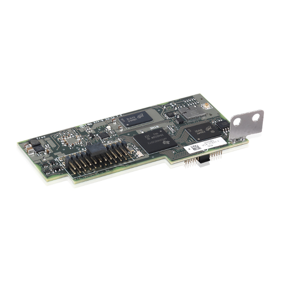
1 - Introduction and general information eference number index , Antenna connection cable , Antenna (RF Technology Corp. Model EA-79 F RP SMA) , Connection terminals , Power supply led , Status led 2 , Status led 1 , Coaxial connector , Mechanical mounting bracket raphical representation of references - 7 -... -
Page 8: The Document And Who It Is For
1- Introduction and general information he document and who it is for urpose and structure of the document This operating and maintenance manual is a useful guide that will enable you to work safely and carry out the operations necessary for keeping the equipment in good working order. -
Page 9: Symbols Ad Signs
1- Introduction and general information ymbols ad signs In the manual and/or in some cases on the equipment, the danger or hazard zones are indicated with signs, labels, symbols or icons. Table: Symbols This points out that it is mandatory to consult the manual or original do- cument, which must be available for future use and must not be dama- ged in any way. -
Page 10: Field Of Use, General Conditions
The device used to transmit data to the Aurora Vision® Plant Management Platform requires a router connected to Internet (the cost of connection is to be paid by the end user). The device can be installed in inverters produced by other manufacturers or in ABB models which can accommodate this type of expansion. -
Page 11: Fcc Warning (Federal Communications Commission)
1 - Introduction and general information CC Warning (Federal Communications Commission) This devices complies with Part 15 of the FCC standard Operation is subject to the following conditions: 1. This device cannot cause harmful disturbances. 2. The device has to accept any disturbance it receives, including disturbance which could compromise correct device operation. -
Page 12: Haracteristics
Characteristics eneral conditions A description of the characteristics of the equipment is given so as to identify its main components and specify the technical terminology used in the manual. Technical terminology and the fast retrieval system for information, are supported by: •... -
Page 13: Models And Range Of Equipment
The labels affixed to the equipment must NOT be removed, damaged, stained, hidden, etc., for any reason whatsoever. The following information which is useful in identifying the product, is printed on the printed circuit of the VSN300 Wifi Logger Card: - Manufacturer's Trade Mark - CE Marking (European Union) - Page 14 In addition to the information printed on the printed circuit, there is also a label on the packaging which can be removed and has other important information: Manufacturer's identification Model identification VSN300 WIFI LOGGER CARD Serial number consisting of: SN: YYWWSSSSSS YY = year of manufacture WW = week of manufacture...
-
Page 15: Characteristics And Technical Data
2 - Characteristics 2 - Characteristics haracteristics and technical data Table: Technical Data VSN300 Wifi Logger Card Communication Hyperlink (CAN@1 Mbps + RS485@115 kBaud) / Legacy (RS232 TTL @ 19.2 Inverter Interface KBaud) User Interface Wi-Fi Certified™ IEEE 802.11 b/g/n (2,4 GHz) -
Page 16: Operating Diagram
2 - Characteristics perating diagram The plant diagram shows how the VSN300 Wifi Logger Card allows the inverter to connect to a LAN local network using a Wi-Fi wireless connection. The VSN300 Wifi Logger Card features an integrated webserver that enables to establish a direct connection to a PC, smartphone or tablet, allowing for board setup and local monitoring of the inverter. -
Page 17: Afety And Accident Prevention
ABB accepts no liability for failure to comply with the instructions for correct installation are cannot be held responsible for the systems upstream or downstream of the equipment it has supplied. -
Page 18: Ifting And Transport
ABB usually stores and protects individual components by suitable means to make their transport and subsequent handling easier, but as a rule it is necessary to turn to the experience of specialized staff in change of loading and unloading the components. -
Page 19: List Of Components Supplied
Arc Fault device Antenna connection cable Wi-Fi Antenna Cable clamp FCC ID label Contains FCC ID: X6W-3N16E Contains FCC ID: X6W-3N16M VSN300 WIFI LOGGER CARD Identification label SN: YYWWSSSSSS MAC: XX:XX:XX:XX:XX:XX PRODUCT KEY: XXXX - XXXX - XXXX - XXXX solar inver... -
Page 20: Nstallation
Installation eneral conditions Installation of the equipment is carried out based on the system and the place in which the equipment is installed; therefore, its performance depends on the correctness of the connections. Staff authorised to carry out the installation must be specialised and experienced in this job;... -
Page 21: Environmental Checks
5 - Installation nvironmental checks The device uses radio waves to transmit and receive data, it is therefore important to assess this factor in order to have optimal installation. Walls in reinforced cement and surfaces covered in metal (doors, shutters, etc.) can markedly reduce the reach of the device which even in optimal conditions, should be of approximately 50 metres in free space. - Page 22 5 - Installation Material of the structure: Concrete Distance X between the Inverter and the Wi-Fi Router: any distance Installation: to be evaluated. Assess the quality of the RF signal and the possibility of extending the signal with a repeater. Material of the structure: Metal or reinforced concrete Distance X between the Inverter and the Wi-Fi...
-
Page 23: Recommendations For The Wi-Fi Signal Power
4. Use an antenna extension cable to connect to the inverter (supplied by ABB). If the inverter is installed in a position which is covered by obstacles, the cable will allow the antenna to be moved to a better position. -
Page 24: Preliminary Operations
5 - Installation reliminary operations Installation of the VSN300 Wifi Logger Card must be carried out inside the inverter and therefore the inverter must be completely disengaged. For the correct disengagement procedure and the subsequent ope- ning of the cover, refer to the manual of the specific inverter. -
Page 25: Mechanical Installation
5 - Installation echanical installation The mechanical installation of the device inside the inverter is a simple operation which does not require any particular tools. However, due to the thickness of the casing, a specific adapter, which is supplied with the device, is required when installing on inverter models UNO-2.0/2.5-I-OUTD and TRIO- 5.8/7.5/8.5-TL-OUTD. -
Page 26: Installation Of The Board
5 - Installation Installation with adapter For installations in inverters for which the adapter is required, proceed as follows: • Install the gasket on the adapter • Secure the adapter to the inverter using the plastic locking nut supplied (tightening torque 5 Nm). •... - Page 27 5 - Installation Install the board by fitting the connection terminals of the specific connector into the inverter board. The inverter board connection, depending on the model, can have a single connector or two separate connectors (see the table at the beginning of the chapter). Installation with dual connector Installation with single connector During this stage, carefully check that all the terminals are correctly aligned.
- Page 28 Once installation has been completed, close the inverter cover and apply the following labels: FCC label: This label is supplied with the VSN300 Wifi Logger Card and must be positioned where it is clearly visible on the outside of the inverter Contains FCC ID: X6W-3N16E in which the board is installed.
-
Page 29: Software Setup
Wi-Fi connection. Switch on the inverter and physically connect the AC and DC grid. The VSN300 Wifi Logger Card switches on automatically and after 60 seconds its own Access Point will be activated. This Access Point is identified by the device selected for the setup (tablet, smartphone or PC). - Page 30 5 - Installation and wait for the device to complete the procedure (a password is not required for the Wi-Fi network). Open the internet browser and enter the pre-set IP address to access the 192.168.117.1 setup page: A guided setup procedure will open, consisting of a sequence of screens in which all the required fields must be completed correctly.
- Page 31 Click on "SCAN" and, from the drop-down menu, select the Wi-Fi ensures better operation. . network to which the VSN300 board is to be connected (if it is to operate in «Station Mode»); or click on "Skip this step" (if the board is to operate in «AP mode»)
- Page 32 5 - Installation Identify and select the appropriate Wi-Fi network from the drop-down menu selecting from amongst the networks detected by the board. A new network search can be carried out by using the Scan button. The networks are ordered on the basis of the power of the signal received in dBm (from the strongest to the weakest).
- Page 33 5 - Installation If Static is selected, the data will appear which has to be entered in order to carry out the IP static address assigning. Complete the additional fields at the bottom of the screen, all the fields are mandatory with the exception of the secondary DNS server. Enter the password for the destination network (if necessary) and start the connection attempt (it will take a few seconds).
- Page 34 Contact the network administrator (DNS) service. for further information regarding In this way, even if the IP address assigned to the VSN300 board should the presence or absence of the change over time, (dynamic IP), it will always be possible to use the DNS service in the Wi-Fi router or same «Host Name»...
-
Page 35: First System And User Setup
Before proceeding with setup, check that the device being used is connected to the same home Wi-Fi network to which the VSN300 board has just been connected. If the device is not connected, select the Wi-Fi network from those shown in the list and connect the device to the network, entering the network protection password if requested to. - Page 36 5 - Installation The next stage of the guided setup procedure will open. In the first screen, enter all the data of the plant to be monitored (mandatory) and click on Next to continue. Check that the longitude and latitude of the installation place are both correct and enter if missing.
- Page 37 5 - Installation After this, the password for the User account is then set. This account is a read only account of the data contained in the integrated Web Server page. Entering this password is not mandatory To set a password, enter it twice and confirm by clicking Next. The password must contain at least 5 alphanumeric characters (UTF-8 code)
- Page 38 5 - Installation Set the password for the Admin account (mandatory in this case) by entering it twice and confirming by clicking Next. As the plant administrator, the Admin account will be able to read and The Admin account password write data contained in the integrated Web Server page and will therefore must be kept safe and must not be be the only one able to modify the plant setting parameters.
- Page 39 - the account on Plant Viewer / Plant Viewer for Mobile has already been created; - the VSN300 board is to be used in «AP Mode» and therefore as a local monitoring instrument with direct Wi-Fi access and not through an Internet connection.
-
Page 40: Nstruments
- there are doubts or contradictions between your experience, the manual and/or other operators. ABB cannot be held responsible for damage to the equipment or the operator if it is the result of incompetence, insufficient qualifications or lack of training. -
Page 41: Led Behaviour
6 - Instruments ED behaviour As soon as the inverter is switched on, the VSN300 board is also automatically powered, in this condition the led 4 emits a red intermittent light. The first time the board is switched on, it acts like an access point («AP Mode»). -
Page 42: Peration
Operation eneral conditions Before checking the operation of the equipment, it is necessary to have a thorough knowledge of the INSTRUMENTS chapter and the functions that have been enabled in the installation. The equipment operates automatically without the aid of an operator; operating state is controlled through the instruments. -
Page 43: Internal Web Server
7 - Operation nternal Web Server The IP address assigned to the board during the guided setup procedure (or the Host Name), can be used at any time for the User or Admin to access the internal Web Server. The IP address assigned may vary for reasons connected to the Wi-Fi home router setup (for example, a very brief DHCP lease time). - Page 44 7 - Operation If User access has been set without a password, the password field will be removed from the screen and the user will be able to access by simply clicking on Sign In. In the event of User protected access, enter the password and click on Sign In.
- Page 45 Summary of technical data of the Wi-Fi board and inverter or real-time operating data. The VSN300 board can be configured in such a way that it transmits or does not transmit the data relating to the Aurora Vision ® platform. - 45 -...
- Page 46 Log of events recorded by the Wi-Fi board The VSN300 board can be configured in such a way that it transmits or does not transmit the events log relating to the Aurora Vision ® platform. The following is provided for each event: SN: Serial number of the device affected by the event;...
- Page 47 7 - Operation installation or by an Admin account. With User access, the settings are read-only. Displays the network, data logging or plant settings Summary of the settings displayed in read only mode - 47 -...
- Page 48 7 - Operation The ABOUT page displays the release notes of the various Firmware versions of the Wi-Fi board. - 48 -...
-
Page 49: Connection With Admin Account
7 - Operation onnection with Admin account Open the internet browser and enter the IP address assigned by the rou- ter at the board identified during the guided procedure. The Admin account password must be kept safe and must not be divulged to novice users. - Page 50 7 - Operation After access, the user is directed to the HOME page where there is a summary of the data relating to the system power identified by the board. The user can access the various Web Server pages from the navigation menu and can logout or change the password from the menu in the top left corner.
- Page 51 7 - Operation The DATA page displays a summary of the most significant technical data for the Wi-Fi board and the inverter. The real-time data is updated every minute, while the system information gathers the main characteri- stics of the installed devices in a table. Instantaneous power Total energy of the day Selection of the Data board in real...
- Page 52 Log of events recorded by the Wi-Fi board The VSN300 board can be configured in such a way that it transmits or does not transmit the events log relating to the Aurora Vision ® platform. The following is provided for each event: SN: Serial number of the device affected by the event;...
- Page 53 Unlike the User access (read only), Admin login allows the settings pre- sent to be modified. As described in the Installation chapter, the VSN300 board can operate in two different operating modes: «Station Mode», with the IP address assigned in static or dynamic mode, and «AP Mode».
- Page 54 300 seconds = 5 minutes) Retention policy: Storage period of the data obtained from the inverter in the internal memory of the VSN300 board In this specific case, 30 days worth of data is archived with a "sliding window" type storage manage- ment, i.e.
- Page 55 (modifiable fields) The main parameters of the inverter can be modified using the Inverter Parameters setting board and since the VSN300 board is installed in the Inverter Parameters setting board, this means that it is not necessary to The function is not available for all operate directly on the board itself.
- Page 56 7 - Operation The ABOUT page displays the release notes of the various Firmware versions of the Wi-Fi board and allows access to the registration page of the Aurora Vision® portal where a new account can be registered. Selection of the release notes or the registration page - 56 -...
-
Page 57: Resetting Passwords
When the operator clicks on «Forgot your password», he will then be required to enter the identification code of the «Product Key» board. VSN300 WIFI LOGGER CARD The «Product Key» is a unique code which can be found on the identifi- SN: YYWWSSSSSS cation label supplied with the board. - Page 58 7 - Operation The procedure for creating a new password is the same as that already carried out during installation. Just as in the installation phase, the USER password is created (optional) and enabled to only read the web interfa- ce parameters.
-
Page 59: Modbus Tcp Gateway Functionality
SunSpec Adapter software. The SunSpec Adapter is a software adapter that has two main functions: it continuously polls legacy ABB inverters as fast as it can using the Au- rora Protocol and caches data polled from these inverters in SunSpec compliant Modbus data maps. - Page 60 Modbus command to the SunSpec Adapter first. When a Modbus TCP client sends read commands to a legacy ABB inverter, the VSN300’s Modbus TCP server will respond based on data that has been cached for that inverter by the SunSpec adapter; when a Modbus TCP client sends a supported write command to a legacy ABB inverter using the inverter’s SunSpec Modbus data map, the SunSpec adapter...
-
Page 61: Modbus Tcp Commands
The VSN300 is able to forward Modbus TCP traffic on port 502. An example of Modbus TCP command sent by the Modbus TCP client to the VSN300 follows::502: . -
Page 62: Firmware Update Function
7 - Operation irmware Update Function This function allows the user to update the Firmware of both the VSN300 board and the inverter within which the board is installed (if anticipated by the inverter model). An incorrect Firmware updating procedure can cause irreversible damage to the VSN300 board or the inverter. -
Page 63: Updates From The Internet
Firmware. If available, a message appears below the button. Choose from Firmware update via access to the ABB remote servers or by loading into the internal memory of the local device Download and update the... -
Page 64: Local Update
Wi-Fi signal is not too weak. Also ensure that the file you are attempting to transfer is the file which has been officially released by ABB and that it is not corrupted. The «UPDATE» key is disabled until the file has been transferred completely. If an error continues to appear, contact ABB technical department for further information. - Page 65 7 - Operation During the Firmware updating process, a progress bar allows the user to see a percentage of the process completion. At the end of the update, the updated device will automatically restart. Firmware update progress bar The Firmware updating operation (particularly regarding the inverter), can require a considerable amount of time.
-
Page 66: Aintenance
Maintenance eneral conditions Checking and maintenance operations must be carried out by specialized staff assigned to carry out this work. Maintenance operations must be performed with the apparatus disconnected from the grid (power switch open) and the photovoltaic panels obscured or isolated, unless otherwise indicated. -
Page 67: Troubleshooting
SSID have spaces in the name ”_”) identified the Wi-Fi network The VSN300 board is not able to connect to a hidden to which connection is The Wi-Fi network to which the network. Set the Wi-Fi network to which the board is... -
Page 68: Event Codes
Aurora Vision® platform is actually the one associated Although the VSN300 platform is not the same as the actual with the VSN300 board installed. If it is not, modify the board has been installed address associated with the VSN300 registered MAC address correctly in “Station Mode”... -
Page 69: Storage And Dismantling
ABB CANNOT be held responsible for disposal of the equipment: displays, cables, batteries, accumulators, etc., and therefore the customer must dispose of these substances, which are potentially harmful to the environment, in accordance with the regulations in force in the country of installation.