Emerson Rosemount 5900S Series Reference Manual
Radar level gauge
Hide thumbs
Also See for Rosemount 5900S Series:
- Reference manual (298 pages) ,
- Quick start manual (56 pages)
Table of Contents
Quick Links
See also:
Reference Manual
Table of Contents
Troubleshooting

Related Manuals for Emerson Rosemount 5900S Series


Summary of Contents for Emerson Rosemount 5900S Series
- Page 1 Reference Manual 00809-0100-5900, Rev CA June 2014 Rosemount 5900S Radar Level Gauge www.rosemount-tg.com...
-
Page 3: Spare Parts
Read this manual before working with the product. For personal and system safety, and for optimum product performance, make sure you thoroughly understand the contents before installing, using, or maintaining this product. For equipment service or support needs, contact your local Emerson Process Management/Rosemount Tank Gauging representative. Spare Parts Any substitution of non-recognized spare parts may jeopardize safety. - Page 4 The products described in this document are NOT designed for nuclear-qualified applications. Using non-nuclear qualified products in applications that require nuclear-qualified hardware or products may cause inaccurate readings. For information on Rosemount nuclear-qualified products, contact your local Rosemount Sales Representative. Cover Photo: 5900_coverphoto.tif...
-
Page 5: Table Of Contents
Reference Manual 00809-0100-5900, Rev CA Rosemount 5900S Series June 2014 Table of Contents SECTION 1 Safety Messages ........1-1 Symbols. - Page 6 Reference Manual 00809-0100-5900, Rev CA Rosemount 5900S Series June 2014 SECTION 4 Safety Messages ........4-1 Configuration Overview .
- Page 7 Reference Manual 00809-0100-5900, Rev CA Rosemount 5900S Series June 2014 4.16 Plantweb Alert Setup ....... . 4-72 4.16.1...
- Page 8 Reference Manual 00809-0100-5900, Rev CA Rosemount 5900S Series June 2014 APPENDIX C Resource Block ........C-2 Fieldbus Analog Input Block.
-
Page 9: Safety Messages
Reference Manual 00809-0100-5900, Rev CA Rosemount 5900S Series June 2014 Section 1 Introduction Safety Messages ......page 1-1 Symbols . -
Page 10: Symbols
Reference Manual 00809-0100-5900, Rev CA Rosemount 5900S Series June 2014 1.2 SYMBOLS The CE marking symbolizes the conformity of the product with the applicable European Community Directives. The EC-Type Examination Certificate is a statement of a Notified Certification Body declaring that this product meets the... -
Page 11: Manual Overview
Reference Manual 00809-0100-5900, Rev CA Rosemount 5900S Series June 2014 1.3 MANUAL This manual provides installation, configuration, and maintenance information for the Rosemount 5900S Series Radar Level Gauge. OVERVIEW Section 2: Overview • Gauge components • System overview • Antenna types •... -
Page 12: Technical Documentation
Reference Manual 00809-0100-5900, Rev CA Rosemount 5900S Series June 2014 1.4 TECHNICAL The Raptor System includes the following documents: DOCUMENTATION • Rosemount Raptor System Data Sheet (704010EN) • Rosemount 5900S Reference Manual (00809-0100-5900) • Rosemount 2410 Reference Manual (300530EN) •... -
Page 13: Service Support
00809-0100-5900, Rev CA Rosemount 5900S Series June 2014 1.5 SERVICE SUPPORT For service support contact the nearest Emerson Process Management/Rosemount Tank Gauging representative. Contact information can be found on the web site www.rosemount-tg.com. 1.6 PRODUCT Recycling of equipment and packaging should be taken into consideration and disposed of in accordance with local and national legislation/regulations. - Page 14 Reference Manual 00809-0100-5900, Rev CA Rosemount 5900S Series June 2014 Section 1. Introduction...
-
Page 15: Introduction
Reference Manual 00809-0100-5900, Rev CA Rosemount 5900S Series June 2014 Section 2 Overview Introduction ....... . page 2-1 Main Label . -
Page 16: Main Label
Reference Manual 00809-0100-5900, Rev CA Rosemount 5900S Series June 2014 2.2 MAIN LABEL Figure 2-2. 5900S main label Model Code Tag no. Serial number Manufacturing date SIL Baseline Device ID IC ID FCC ID Explosion protection Explosion protection Section 2. Overview... -
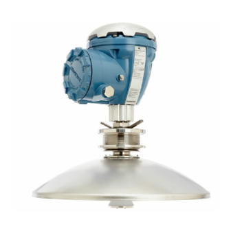
Page 17: Components
Reference Manual 00809-0100-5900, Rev CA Rosemount 5900S Series June 2014 2.3 COMPONENTS Figure 2-3. Rosemount 5900S components 1. Terminal compartment 2. Cable entries (½ - 14 NPT, M20 x 1.5 adapters) 3. Flange 4. Antenna 5. Grounding terminal 6. Weather protection hood 7. -
Page 18: System Overview
Reference Manual 00809-0100-5900, Rev CA Rosemount 5900S Series June 2014 2.4 SYSTEM Raptor is a state-of-the art inventory and custody transfer radar tank level gauging system. It is developed for a wide range of applications at refineries, OVERVIEW tank farms and fuel depots, and fulfills the highest requirements on performance and safety. - Page 19 Reference Manual 00809-0100-5900, Rev CA Rosemount 5900S Series June 2014 Figure 2-4. Rosemount Tank Gauging System architecture 2240S Temperature 5900S Radar Transmitter Level Gauge NON-HAZARDOUS AREA HAZARDOUS AREA TankMaster PC 2230 Display 2410 Tank Hub 3051S Pressure Transmitter Tankbus 2160 Field...
- Page 20 Reference Manual 00809-0100-5900, Rev CA Rosemount 5900S Series June 2014 Figure 2-5. Rosemount Tank Gauging system architecture for wireless systems NON-HAZARDOUS AREA HAZARDOUS AREA 2240S Temperature 5900S Radar Transmitter Level Gauge THUM TankMaster PC 2230 Display 2410 Tank Hub 3051S...
- Page 21 Reference Manual 00809-0100-5900, Rev CA Rosemount 5900S Series June 2014 Figure 2-6. Rosemount Tank Gauging system architecture in a Foundation fieldbus network 2240S Temperature 5900S Radar Transmitter Level Gauge NON-HAZARDOUS AREA HAZARDOUS AREA 2230 Display 3051S Pressure Transmitter FOUNDTION Fieldbus...
- Page 22 Reference Manual 00809-0100-5900, Rev CA Rosemount 5900S Series June 2014 TankMaster HMI Software TankMaster is a powerful Windows-based Human Machine Interface (HMI) for complete tank inventory management. It provides configuration, service, set-up, inventory, and custody transfer functions for Raptor systems and other supported instruments.
- Page 23 Reference Manual 00809-0100-5900, Rev CA Rosemount 5900S Series June 2014 The Rosemount 5900S sends microwaves towards the surface of the product in the tank. The level is calculated based on the echo from the surface. No part of the 5900S is in actual contact with the product in the tank, and the antenna is the only part of the gauge that is exposed to the tank atmosphere.
- Page 24 Reference Manual 00809-0100-5900, Rev CA Rosemount 5900S Series June 2014 Rosemount Smart Wireless Gateway and Rosemount Smart Wireless THUM Adapter A THUM Adapter allows wireless communication between a 2410 Tank Hub and a Smart Wireless Gateway. The gateway is the network manager that provides an interface between field devices and the TankMaster inventory software or host / DCS systems.
-
Page 25: Antennas
Reference Manual 00809-0100-5900, Rev CA Rosemount 5900S Series June 2014 2.5 ANTENNAS The Rosemount 5900S with Horn Antenna is designed for an 8 inch antenna to be used in small size openings on fixed roofs tanks. The 5900S is designed for measurements of a variety of oil products and chemicals. - Page 26 Reference Manual 00809-0100-5900, Rev CA Rosemount 5900S Series June 2014 The Rosemount 5900S with LPG/LNG Antenna is designed for level measurements in LPG and LNG tanks. A 4 inch still-pipe is used as a wave guide for the measurement and prevents a turbulent surface from disturbing the measurement.
-
Page 27: Installation Procedure
Reference Manual 00809-0100-5900, Rev CA Rosemount 5900S Series June 2014 2.6 INSTALLATION Follow these steps for proper installation: PROCEDURE Review Installation Considerations. See “Installation Considerations” on page 3-3. Mount the gauge. See “Mechanical Installation” on page 3-19. Wire the gauge. - Page 28 Reference Manual 00809-0100-5900, Rev CA Rosemount 5900S Series June 2014 Section 2. Overview 2-14...
-
Page 29: Safety Messages
Reference Manual 00809-0100-5900, Rev CA Rosemount 5900S Series June 2014 Section 3 Installation Safety Messages ......page 3-1 Installation Considerations . - Page 30 Reference Manual 00809-0100-5900, Rev CA Rosemount 5900S Series June 2014 High voltage that may be present on leads could cause electrical shock: Avoid contact with leads and terminals. Make sure the main power to the transmitter is off and the lines to any other external power source are disconnected or not powered while wiring the gauge.
-
Page 31: Installation Considerations
Reference Manual 00809-0100-5900, Rev CA Rosemount 5900S Series June 2014 3.2 INSTALLATION When finding an appropriate location on the tank for a Rosemount 5900S Radar Level Gauge, the conditions of the tank must be carefully considered. CONSIDERATIONS The 5900S should be installed so that the influence of disturbing objects is kept to a minimum, preferably outside the radar signal beam. -
Page 32: Horn Antenna Requirements
Reference Manual 00809-0100-5900, Rev CA Rosemount 5900S Series June 2014 3.2.1 Horn Antenna The Rosemount 5900S with Horn Antenna must be installed so that there are no pipes or other obstacles that could prevent the radar beam from reaching Requirements the tank bottom unobstructed. - Page 33 4° flange (1) In exceptional cases the 5900S with Horn Antenna can be installed closer to the tank wall if required. Please contact Emerson Process Management / Rosemount Tank Gauging for advice. In certain cases, when maximum accuracy is not required, the horizontal flange can be used even if the wall intrudes into the radar beam.
-
Page 34: Parabolic Antenna Requirements
Reference Manual 00809-0100-5900, Rev CA Rosemount 5900S Series June 2014 3.2.2 Parabolic Inclination Antenna The inclination of the Rosemount 5900S with Parabolic Antenna should not Requirements exceed 1.5 ° towards the center of the tank. For products with high condensation such as bitumen/asphalt applications, the radar beam should be directed vertically without any inclination. - Page 35 Reference Manual 00809-0100-5900, Rev CA Rosemount 5900S Series June 2014 Figure 3-4. Maximum inclination of tank flange Maximum inclination towards tank center Maximum inclination towards tank wall In case the tank flange does not meet the requirements as illustrated in Figure 3-4, the inclination requirements for the Parabolic Antenna can still be met by using the welded Flange Ball.
- Page 36 Reference Manual 00809-0100-5900, Rev CA Rosemount 5900S Series June 2014 Nozzle Requirements When installing the 5900S with Parabolic Antenna on a Ø 20" nozzle, the nozzle height must not exceed 600 mm. There has to be a free passage for the radar beam within a 5°...
- Page 37 5900S with Parabolic Antenna for installation and service Recommended space 500 mm for installation and service Free passage 5° 5° Vertical plumb Antenna axis Max. 1.5 ° Min. 0.8 m For evaluation contact Emerson Process Management / Rosemount Tank Gauging. Section 3. Installation...
-
Page 38: Still-Pipe Antenna Requirements
SCH10-SCH60 161.5 - 150.3 SCH20-SCH80 206.3 - 193.7 SCH10-SCH60 264.7 - 247.7 293.5 SCH 10-40-XS 314.7 - 298.5 Please contact Emerson Process Management / Rosemount Tank Gauging for advice if this requirement can not be met. Section 3. Installation 3-10... - Page 39 In some cases it is possible to allow a larger total area than stated in Table 3-4. When the limits are exceeded, please contact Emerson Process Management / Rosemount Tank Gauging for advice.
- Page 40 Reference Manual 00809-0100-5900, Rev CA Rosemount 5900S Series June 2014 Free Space The following free space is recommended for mounting the 5900S with Still-pipe Array Antenna: Figure 3-9. Free space requirements for 5900S with Recommended space 550 mm Array antenna Fix version...
- Page 41 Reference Manual 00809-0100-5900, Rev CA Rosemount 5900S Series June 2014 3.2.4 LPG/LNG Temperature and Pressure Measurement Antenna Measurements of temperature and pressure is a prerequisite for high Requirements accuracy level measurements in LPG/LNG tanks. A Raptor system may include 5900S Radar Level Gauges, 2240S Multi-input Temperature Transmitters, 644 Temperature Transmitters as well as pressure transmitters in order to obtain all necessary measurement variables.
- Page 42 Reference Manual 00809-0100-5900, Rev CA Rosemount 5900S Series June 2014 Figure 3-11. Installation of Verification Pin and inclination requirements for flange and still-pipe Mark on still-pipe flange The Verification Pin is 1000 < L < 2500 mm directed towards the bolt...
- Page 43 Reference Manual 00809-0100-5900, Rev CA Rosemount 5900S Series June 2014 Deflection Plate with Calibration Ring A Deflection Plate is mounted at the lower end of the still-pipe and is integrated with a ring that is used for calibrating the gauge during the installation phase when the tank is empty.
- Page 44 Reference Manual 00809-0100-5900, Rev CA Rosemount 5900S Series June 2014 Figure 3-13. Mounting the Deflection Plate on pipe 4 inch SCH 40 Ring is marked 4” SCH40 Figure 3-14. Mounting the Deflection Plate on pipe DN 100 Ring is marked DN100 Section 3.
-
Page 45: Lpg/Lng Antenna Requirements
Reference Manual 00809-0100-5900, Rev CA Rosemount 5900S Series June 2014 Free Space The following free space is recommended for mounting the 5900S with LPG/LNG Antenna: Figure 3-15. Free space requirements for 5900S with Recommended space 550 mm LPG/LNG antenna for installation and service... - Page 46 Reference Manual 00809-0100-5900, Rev CA Rosemount 5900S Series June 2014 Extension Pipe for Minimum Distance The 5900S Radar Level Gauge should be placed such that there is a minimum gap of 1200 mm between the flange and the maximum product level (see “Still-pipe and Verification Pin”...
-
Page 47: Mechanical Installation
Reference Manual 00809-0100-5900, Rev CA Rosemount 5900S Series June 2014 3.3 MECHANICAL INSTALLATION 3.3.1 Horn Antenna Follow this instruction when installing the Rosemount 5900S with Horn Antenna. See “Horn Antenna Requirements” on page 3-4 for information on mounting considerations before installing the gauge on the tank. - Page 48 Reference Manual 00809-0100-5900, Rev CA Rosemount 5900S Series June 2014 6. Put the transmitter head onto the antenna adapter. Transmitter head 7. Ensure that the guide pin inside the transmitter head fits the groove on the adapter. 8. Tighten the nut that connects the transmitter head to the adapter.
-
Page 49: Parabolic Antenna
Reference Manual 00809-0100-5900, Rev CA Rosemount 5900S Series June 2014 3.3.2 Parabolic Mounting the clamped Flange Ball Antenna To mount the clamped Flange Ball do the following: 1. Use a flange of thickness 6 - 30 mm. 2. Make sure that the diameter of the Recess hole is 96 mm. - Page 50 Reference Manual 00809-0100-5900, Rev CA Rosemount 5900S Series June 2014 Mounting the welded Flange Ball To mount the welded Flange Ball do the following: 1. For horizontal mounting according to requirements in chapter “Parabolic 116±2 mm Antenna Requirements” on page 3-6, make sure that the diameter of the hole is 116 ±...
- Page 51 Reference Manual 00809-0100-5900, Rev CA Rosemount 5900S Series June 2014 5. If the tank flange is inclined, make sure that the Flange Ball is welded 60 mm so that the Flange Ball is horizontal when it is mounted on the tank.
- Page 52 Reference Manual 00809-0100-5900, Rev CA Rosemount 5900S Series June 2014 Mounting the Parabolic Antenna Follow this instruction when installing the Parabolic antenna. See “Parabolic Antenna Requirements” on page 3-6 for considerations before installing the gauge on the tank. 1. Check that all parts and tools are...
- Page 53 Reference Manual 00809-0100-5900, Rev CA Rosemount 5900S Series June 2014 4. Put the two O-rings in the grooves on the upper surface of the Flange Ball. 2 O-rings Flange Ball Grooves Flange 5. Turn the flange around and insert the Antenna Waveguide into the flange hole.
- Page 54 Reference Manual 00809-0100-5900, Rev CA Rosemount 5900S Series June 2014 8. Tighten the finger nut and the upper nut by hand. Upper Nut Finger Nut 9. Place the antenna and flange Antenna Waveguide assembly on the tank nozzle and Flange tighten the flange screws.
- Page 55 Reference Manual 00809-0100-5900, Rev CA Rosemount 5900S Series June 2014 10. Put the level gauge on the Antenna Waveguide. Ensure that the guide pin inside the transmitter head fits into the groove on the Antenna Waveguide. 11. Tighten the nut that connects the transmitter head to the antenna.
- Page 56 Reference Manual 00809-0100-5900, Rev CA Rosemount 5900S Series June 2014 15. Use the marks on the Washer Ball to adjust the gauge so the antenna is Marks inclined roughly 1.5° towards the center of the tank. Note: For products with high condensation, such as bitumen, the 0.5°...
- Page 57 Reference Manual 00809-0100-5900, Rev CA Rosemount 5900S Series June 2014 19. In case the Weather Protection Hood Weather was removed, put it back on top of Protection Hood the transmitter head and tighten the screw. Finger Nut 20. Tighten the upper nut to lock the...
-
Page 58: Array Antenna - Fix Version
Reference Manual 00809-0100-5900, Rev CA Rosemount 5900S Series June 2014 3.3.3 Array Antenna - Follow this Step by Step instruction when installing the Array Antenna Fixed version. See “Still-pipe Antenna Requirements” on page 3-10 for information Fix version on mounting considerations before installing the gauge on the tank. - Page 59 Reference Manual 00809-0100-5900, Rev CA Rosemount 5900S Series June 2014 5. Put the antenna and flange assembly on the tank nozzle and tighten the flange screws. 6. Carefully put the gauge on top of the Weather Antenna Waveguide and tighten the Protection Hood nut.
- Page 60 Reference Manual 00809-0100-5900, Rev CA Rosemount 5900S Series June 2014 8. Connect the electrical cabling and configure the 5900S by using the TankMaster WinSetup software, see the Raptor System Configuration Manual (Document No. 300510EN). Section 3. Installation 3-32...
-
Page 61: Array Antenna - Hinged Hatch
Reference Manual 00809-0100-5900, Rev CA Rosemount 5900S Series June 2014 3.3.4 Array Antenna - Follow this instruction when installing the Array antenna Hinged Hatch version. Hinged Hatch 1. Mount the hatch on the nozzle. The hatch has a welded flange with a hole Gasket pattern that fits the nozzle flange. - Page 62 Reference Manual 00809-0100-5900, Rev CA Rosemount 5900S Series June 2014 4. Tighten the nut which holds the antenna to the lid. 5. Check that the O-ring is properly seated all around the cover and is O-ring pressed down behind the Hand Dip Plate.
- Page 63 Reference Manual 00809-0100-5900, Rev CA Rosemount 5900S Series June 2014 6. Close the lid and tighten the locking Antenna Waveguide screw. Tighten the locking screw 7. Carefully put the gauge on top of the Weather Antenna Waveguide and tighten the Protection Hood nut.
- Page 64 Reference Manual 00809-0100-5900, Rev CA Rosemount 5900S Series June 2014 9. Connect the electrical cabling and configure the gauge by using the TankMaster WinSetup software (see the Raptor System Configuration Manual, Document No. 300510EN) Section 3. Installation 3-36...
-
Page 65: Lpg/Lng Antenna
Reference Manual 00809-0100-5900, Rev CA Rosemount 5900S Series June 2014 3.3.5 LPG/LNG Follow this step by step instruction when installing the LPG/LNG antenna. See “LPG/LNG Antenna Requirements” on page 3-13 for information on Antenna mounting considerations before installing the gauge on the tank. - Page 66 Reference Manual 00809-0100-5900, Rev CA Rosemount 5900S Series June 2014 5. Place a gasket (customer supplied) on the still-pipe flange. 6. Carefully fit the antenna into the still-pipe. 7. Direct the closing so that the mark Closing aligns with the notch on the pipe flange.
- Page 67 Reference Manual 00809-0100-5900, Rev CA Rosemount 5900S Series June 2014 11. Put the adapter on the flange. Pressure transmitter Ensure that the guide pins on the flange fit the holes at the bottom of the Four M10 screws adapter. 12. Ensure that the mark on top of the...
- Page 68 Reference Manual 00809-0100-5900, Rev CA Rosemount 5900S Series June 2014 18. Verify that the level gauge head is Mark that indicates properly aligned. The cover on the direction of the terminal compartment shall be parallel Verification Pin 5900 level with the Verification Pin.
-
Page 69: Electrical Installation
Reference Manual 00809-0100-5900, Rev CA Rosemount 5900S Series June 2014 3.4 ELECTRICAL INSTALLATION 3.4.1 Cable/conduit The electronics housing has two entries for ½ - 14 NPT. Optional M20×1.5, minifast and eurofast adapters are also available. The connections must be entries made in accordance with local or plant electrical codes. -
Page 70: Cable Selection
3.4.3 Cable Selection Use shielded twisted pair wiring for the Rosemount 5900S Series in order to comply with FISCO requirements and EMC regulations. The preferred cable is referred to as type “A” fieldbus cable. The cables must be suitable for the supply voltage and approved for use in hazardous areas, where applicable. -
Page 71: The Raptor Tankbus
Reference Manual 00809-0100-5900, Rev CA Rosemount 5900S Series June 2014 3.4.7 The Raptor The Raptor system is easy to install and wire. Devices can be “daisy-chained” thus reducing the number of external junction boxes. Tankbus In a Raptor system devices communicate with a Rosemount 2410 Tank Hub via the intrinsically safe Tankbus. -
Page 72: Typical Installation
Reference Manual 00809-0100-5900, Rev CA Rosemount 5900S Series June 2014 3.4.8 Typical The example below (Figure 3-18) illustrates a system with daisy-chained field devices on a single tank. Terminators are installed at both ends of the fieldbus installation segment as required in a F fieldbus system. -
Page 73: 5900S In Foundation Fieldbus System
Reference Manual 00809-0100-5900, Rev CA Rosemount 5900S Series June 2014 3.4.9 5900S in The Rosemount 5900S Radar Level Gauge supports the F fieldbus OUNDATION (FF) technology and lets you integrate a 5900S into an existing FF network. OUNDATION As long as the power supply meets certain requirements (see Figure 3-19 and... -
Page 74: Wiring
Reference Manual 00809-0100-5900, Rev CA Rosemount 5900S Series June 2014 3.4.10 Wiring To connect the Rosemount 5900S level gauge: 1. Ensure that the power supply is switched off. 2. Remove the cover on the terminal compartment. 3. Run the wires through the appropriate cable gland/conduits. - Page 75 Reference Manual 00809-0100-5900, Rev CA Rosemount 5900S Series June 2014 Conductor Recommendations Ensure that you use cables suitable for the terminal block of the 5900S. The terminal block is designed for cables that meet the specifications as illustrated below. Figure 3-22. Conductor and...
- Page 76 Reference Manual 00809-0100-5900, Rev CA Rosemount 5900S Series June 2014 A solid conductor, or a flexible conductor with end ferrule, can easily be pushed into the terminal block without using any tools. In case a flexible (stranded) conductor is used, you will have to push the release button in order to insert the conductor.
-
Page 77: Terminal Blocks
Reference Manual 00809-0100-5900, Rev CA Rosemount 5900S Series June 2014 3.4.11 Terminal Blocks Figure 3-25. Rosemount 5900S terminal compartment Test terminals Test terminals Ground terminals, internal Table 3-7. Terminal block connections for the 5900S Connection Description X1: Tankbus in Intrinsically safe Tankbus input, power and communication (spur... - Page 78 Reference Manual 00809-0100-5900, Rev CA Rosemount 5900S Series June 2014 Terminal Block Two-in-One Version The Rosemount 5900S Two-in-One version can be connected to a single Tankbus or two separate Tankbuses. Figure 3-26. Terminal compartment.2-in-1 version Two tankbuses Single tankbus Test...
- Page 79 Reference Manual 00809-0100-5900, Rev CA Rosemount 5900S Series June 2014 Gauge Terminal Block SIL Safety System The Rosemount 5900S has a SIL2/SIL3 alarm output which is connected to the Rosemount 2410 Tank Hub. Figure 3-27. Terminal compartment 2-in-1: optional jumpers...
-
Page 80: Wiring Diagrams
Reference Manual 00809-0100-5900, Rev CA Rosemount 5900S Series June 2014 3.4.12 Wiring Diagrams The standard version of the Rosemount 5900S has a single intrinsically safe fieldbus input. The 5900S has a built-in termination by short-circuiting the X2 connector. An intrinsically safe output on connector X4 can be used for “daisy-chain”... - Page 81 Reference Manual 00809-0100-5900, Rev CA Rosemount 5900S Series June 2014 The Rosemount 5900S 2-in-1 version The 2-in-1 version of the Rosemount 5900S has two separate level gauges in the same housing. One of the tankbuses can be terminated in the 5900S terminal compartment.
- Page 82 Reference Manual 00809-0100-5900, Rev CA Rosemount 5900S Series June 2014 Figure 3-30 illustrates the 2-in-1 version of the Rosemount 5900S with a single intrinsically safe Tankbus. The Tankbus is connected to the first level gauge via terminal X1, and to the second level gauge via a jumper between terminals X3 (Primary Tankbus out) and X4 (Secondary Tankbus in).
- Page 83 Reference Manual 00809-0100-5900, Rev CA Rosemount 5900S Series June 2014 In Figure 3-31 a Rosemount 2240S transmitter is wired to the second level gauge of a 2-in-1 version of the Rosemount 5900S Radar Level Gauge. The Primary Tankbus is terminated in the 5900S terminal block (X2). The Secondary Tankbus is terminated by enabling the built-in termination of the 2240S temperature transmitter.
- Page 84 Reference Manual 00809-0100-5900, Rev CA Rosemount 5900S Series June 2014 Section 3. Installation 3-56...
-
Page 85: Safety Messages
Reference Manual 00809-0100-5900, Rev CA Rosemount 5900S Series June 2014 Section 4 Configuration Safety Messages ......page 4-1 Overview . - Page 86 Reference Manual 00809-0100-5900, Rev CA Rosemount 5900S Series June 2014 Explosions could result in death or serious injury: Verify that the operating environment of the transmitter is consistent with the appropriate hazardous locations certifications. Before connecting a communicator in an explosive atmosphere, make sure the instruments in the loop are installed in accordance with intrinsically safe or non-incendive field wiring practices.
-
Page 87: Overview
Reference Manual 00809-0100-5900, Rev CA Rosemount 5900S Series June 2014 4.2 OVERVIEW The 5900S can be installed in Rosemount Tank Gauging systems including 2160 Field Communication Units and Rosemount 2410 Tank Hubs. The 5900S also supports installation in F fieldbus systems. Installation OUNDATION of the 5900S is a simple and straight-forward procedure. -
Page 88: Basic Configuration
Reference Manual 00809-0100-5900, Rev CA Rosemount 5900S Series June 2014 The Rosemount 5900S supports basic configuration which is sufficient in most cases. There are a number of advanced configuration options available as well, which may be used for special applications when further fine-tuning is needed. -
Page 89: Configuration Using Rosemount Tankmaster
Reference Manual 00809-0100-5900, Rev CA Rosemount 5900S Series June 2014 4.3 CONFIGURATION For a Rosemount Tank Gauging system that includes the Rosemount 2410 Tank Hub it is recommended that the Rosemount 5900S is configured by USING using the TankMaster Winsetup configuration tool. In such a system the host... -
Page 90: Basic Configuration
Reference Manual 00809-0100-5900, Rev CA Rosemount 5900S Series June 2014 4.4 BASIC CONFIGURATION 4.4.1 Tank Geometry The following parameters are used for tank geometry configuration of a Rosemount 5900S Radar Level Gauge: Figure 4-1. Tank geometry parameters for the 5900S... - Page 91 Reference Manual 00809-0100-5900, Rev CA Rosemount 5900S Series June 2014 The 5900S with Array Antenna and hinged hatch allows you to hand dip by opening the lid and moving the gauge away from the tank opening. A hand dip plate is located inside the hatch. The plate is used as the Tank Reference Point for the tank geometry parameter Tank Height (R).
- Page 92 Reference Manual 00809-0100-5900, Rev CA Rosemount 5900S Series June 2014 Tank Reference Height (R) The Tank Reference Height (R) is the distance from the hand dipping nozzle (Tank Reference Point) to the Zero Level (Dipping Datum Plate) close to, or at the bottom of the tank.
- Page 93 Reference Manual 00809-0100-5900, Rev CA Rosemount 5900S Series June 2014 Calibration Distance Use this variable to calibrate the 5900S so that measured product levels match hand dipped levels. A minor adjustment may be necessary when the gauge is installed if, for example, there is a deviation between the actual tank height and the height given by tank drawings.
-
Page 94: Tank Scan
Reference Manual 00809-0100-5900, Rev CA Rosemount 5900S Series June 2014 4.4.2 Tank Scan The Tank Scan window is a useful tool for analyzing the Rosemount 5900S measurement signal. It allows you to view tank echoes and setup the most important parameters to enable the gauge to distinguish between the surface echo and disturbing echoes and noise. -
Page 95: Empty Tank Handling
Reference Manual 00809-0100-5900, Rev CA Rosemount 5900S Series June 2014 4.4.3 Empty Tank The Rosemount 5900S Empty Tank Handling function handles situations when the surface echo is close to the tank bottom. It has the ability to: Handling • track weak product echoes •... - Page 96 Reference Manual 00809-0100-5900, Rev CA Rosemount 5900S Series June 2014 Activate Extra Echo Function The Extra Echo Detection function is used for tanks with a dome or conical bottom shape provided the tank bottom does not produce a strong echo when the tank is empty.
- Page 97 Reference Manual 00809-0100-5900, Rev CA Rosemount 5900S Series June 2014 Bottom Echo Visible if Tank is Empty By using this function the level gauge will be able to track relatively weak surface echoes close to the tank bottom by treating the bottom echo as a disturbance echo.
- Page 98 Reference Manual 00809-0100-5900, Rev CA Rosemount 5900S Series June 2014 Empty Tank Detection Area The Empty Tank Detection Area defines a range within a lower limit of 200 mm (8 in.) above the tank bottom. If the surface echo is lost in this region, the tank is considered empty (the device enters Empty Tank State) and the level gauge presents a zero level reading.
-
Page 99: Advanced Configuration
Reference Manual 00809-0100-5900, Rev CA Rosemount 5900S Series June 2014 4.5 ADVANCED There are a number of advanced configuration options for the Rosemount 5900S gauge which may be useful in certain situations. These options are CONFIGURATION available via TankMaster Winsetup and the 5900 RLG Properties window. -
Page 100: Surface Echo Tracking
Reference Manual 00809-0100-5900, Rev CA Rosemount 5900S Series June 2014 4.5.3 Surface Echo The Surface Echo Tracking function can be used to eliminate problems with certain types of ghost echoes below the product surface. This may, for Tracking example, occur in still-pipes as a result of multiple reflections between the pipe wall, flange and antenna. - Page 101 Reference Manual 00809-0100-5900, Rev CA Rosemount 5900S Series June 2014 Close Distance This parameter defines a window centered at the current surface position in which new surface echo candidates can be selected. The size of the window is ±Close Distance. Echoes outside this window will not be considered as surface echoes.
-
Page 102: Filter Setting
Reference Manual 00809-0100-5900, Rev CA Rosemount 5900S Series June 2014 4.5.4 Filter Setting To open the Filter Setting window: 1. In the TankMaster WinSetup workspace, click the right mouse button on the desired 5900S Radar Level Gauge icon. 2. Choose the Properties option from the popup menu. - Page 103 Reference Manual 00809-0100-5900, Rev CA Rosemount 5900S Series June 2014 Least Square Filter The Least Square filter gives increased accuracy for slow filling or emptying of a tank. The level value follows the surface with high accuracy and without delay as the level changes. The Least Square filter can not be used at the same time as the Adaptive Filter.
-
Page 104: Lpg Configuration
Reference Manual 00809-0100-5900, Rev CA Rosemount 5900S Series June 2014 4.6 LPG CONFIGURATION 4.6.1 Preparations Before starting configuration of the Rosemount 5900S for LPG measurements, ensure that all mechanical installations are made according to instructions, and all external sensors such as pressure and temperature sensors are properly connected. -
Page 105: Lpg Setup Using Tankmaster
Reference Manual 00809-0100-5900, Rev CA Rosemount 5900S Series June 2014 4.6.2 LPG Setup Using In the following description it is assumed that the Rosemount 5900S with LPG/LNG Antenna is installed on the tank, and a basic configuration is TankMaster performed as described in the Raptor System Configuration Manual (Document no. - Page 106 Reference Manual 00809-0100-5900, Rev CA Rosemount 5900S Series June 2014 Rosemount 644 Temperature Transmitters have to be mapped manually in order to provide input for Vapor Temperature and Average Liquid Temperature calculations. Note that the actual Vapor Temperature and Liquid Temperature tank parameters are not mapped.
- Page 107 Reference Manual 00809-0100-5900, Rev CA Rosemount 5900S Series June 2014 5. In the TankMaster WinSetup work space choose the Logical View tab. Select the icon that represents the radar level gauge, click the right mouse button and choose LPG Setup.
- Page 108 Reference Manual 00809-0100-5900, Rev CA Rosemount 5900S Series June 2014 8. Calibrate. Ensure that there is no liquid above the calibration ring at the end of the still-pipe when calibrating the gauge. When there is no product above the calibration ring, this is the only object that will be detected by the gauge.
- Page 109 Gauge Reference Point to the actual position of the Verification Pin. Since hand dipping can not be performed in high pressurized tanks, Emerson Process Management / Rosemount Tank Gauging has developed a unique method to verify level gauging in such tanks. The method is based on measurements in a special radar wave propagation mode against a fixed Verification Pin in order to verify the measurement.
- Page 110 Reference Manual 00809-0100-5900, Rev CA Rosemount 5900S Series June 2014 GAUGE REFERENCE POINT Distance from gauge reference point to Verification Pin VERIFICATION PIN Ensure that the Threshold value is 500 mV. The amplitude of the echo from the Verification Pin must be above the threshold value in order to appear in the LPGVerify window (see “Verify the...
- Page 111 Reference Manual 00809-0100-5900, Rev CA Rosemount 5900S Series June 2014 10. Verify the gauge measurement. a. In the LPG Setup window click the Verify Pins button in order to open the LPG Verify Pins window. Ensure that the Nominal Position of the Verification Pin appears:...
- Page 112 Reference Manual 00809-0100-5900, Rev CA Rosemount 5900S Series June 2014 11. Choose correction method. There are several options available depending on gas mixture in the tank. In the LPG Setup window click the Correction button to open the LPG Correction window: Choose one of the following correction methods: a.
-
Page 113: Calibration Using Winsetup
Reference Manual 00809-0100-5900, Rev CA Rosemount 5900S Series June 2014 4.7 CALIBRATION The Calibrate function is a TankMaster WinSetup tool that lets you adjust a Rosemount 5900S level gauge in order to minimize the offset between actual USING WINSETUP (hand dipped) product levels and the values measured by the level gauge. By using the Calibrate function you can optimize measurement performance over the whole measurement range from the top to the bottom of the tank. - Page 114 Reference Manual 00809-0100-5900, Rev CA Rosemount 5900S Series June 2014 Procedure Follow these instructions when you make hand dip measurements: • hand dip until three consecutive readings within 1 mm are obtained • correct the tape according to the calibration record •...
- Page 115 Reference Manual 00809-0100-5900, Rev CA Rosemount 5900S Series June 2014 To enter calibration data 1. In the TankMaster WinSetup workspace window select the 5900S level gauge to be calibrated. 2. Click the right mouse button and choose Calibrate, or choose Calibrate from the Service/Devices menu.
- Page 116 Reference Manual 00809-0100-5900, Rev CA Rosemount 5900S Series June 2014 6. Click the Refresh button. Now WinSetup calculates the deviations between hand dipped and measured levels. 7. Click the Save Calibration Data in PC Database button in order to save the entered values and return to the Calibrate window.
- Page 117 Reference Manual 00809-0100-5900, Rev CA Rosemount 5900S Series June 2014 Now you can check the calibration result by opening the Calibration window again: Note that all measured values are adjusted according to the calculated Calibration Distance and Correction Factor. In the Calibration Data window you can also see that the level values measured by the 5900S gauge are adjusted.
-
Page 118: Foundation Fieldbus Overview
FIELDBUS OUNDATION OVERVIEW For detailed information about F Fieldbus technology and function OUNDATION blocks used in the Rosemount 5900S Series, refer to Appendix C: Foundation Fieldbus Block Information and the F Fieldbus Blocks Manual OUNDATION (Document No. 00809-0100-4783). 4.8.1 Block Operation Function blocks within the fieldbus device perform the various functions required for process control. - Page 119 Reference Manual 00809-0100-5900, Rev CA Rosemount 5900S Series June 2014 LPG Transducer Block (TB1500) The LPG Transducer Block contains parameters for setup and configuration of the LPG calculations, and for verification and status of the corrections. Analog Input Block Figure 4-11. Analog-Input Block...
- Page 120 Reference Manual 00809-0100-5900, Rev CA Rosemount 5900S Series June 2014 Signal Characterizer Block The Signal Characterizer (SGCR) Function Block characterizes or approximates any function that defines an input/output relationship. The function is defined by configuring as many as twenty X,Y coordinates. The block interpolates an output value for a given input value using the curve defined by the configured coordinates.
- Page 121 Reference Manual 00809-0100-5900, Rev CA Rosemount 5900S Series June 2014 Function Block Summary The following function blocks are available for the Rosemount 5900S Series: • Analog Input (AI) • Analog Output (AO) • Proportional/Integral/Derivative (PID) • Signal Characterizer (SGCR) •...
-
Page 122: Device Capabilities
Reference Manual 00809-0100-5900, Rev CA Rosemount 5900S Series June 2014 4.9 DEVICE CAPABILITIES 4.9.1 Link Active The Rosemount 5900S can be designated to act as the backup Link Active Scheduler (LAS) in the event that the LAS is disconnected from the segment. -
Page 123: General Block Information
Reference Manual 00809-0100-5900, Rev CA Rosemount 5900S Series June 2014 4.10 GENERAL BLOCK INFORMATION 4.10.1 Modes Changing Modes To change the operating mode, set the MODE_BLK.TARGET to the desired mode. After a short delay, the parameter MODE_BLOCK.ACTUAL should reflect the mode change if the block is operating properly. -
Page 124: Block Instantiation
Reference Manual 00809-0100-5900, Rev CA Rosemount 5900S Series June 2014 4.10.2 Block The Rosemount 5900S supports the use of Function Block Instantiation. When a device supports block instantiation, the number of blocks and block Instantiation types can be defined to match specific application needs.The number of blocks that can be instantiated is only limited by the amount of memory within the device and the block types that are supported by the device. -
Page 125: Analog Input Block
Reference Manual 00809-0100-5900, Rev CA Rosemount 5900S Series June 2014 4.11 ANALOG INPUT BLOCK 4.11.1 Configure the AI A minimum of four parameters are required to configure the AI Block. The parameters are described below with example configurations shown at the Block end of this section. -
Page 126: Factory Supplied Ai Blocks
Reference Manual 00809-0100-5900, Rev CA Rosemount 5900S Series June 2014 L_TYPE is Indirect When an inferred measurement is made based on the sensor measurement, set the XD_SCALE to represent the operating range that the sensor will see in the process. Determine the inferred measurement values that correspond to the XD_SCALE 0 and 100% points and set these for the OUT_SCALE. -
Page 127: Simulation
Reference Manual 00809-0100-5900, Rev CA Rosemount 5900S Series June 2014 4.11.4 Simulation To perform lab test of process variables and alerts, you can either change the mode of the AI block to manual and adjust the output value, or you can enable simulation through the configuration tool and manually enter a value for the measurement value and its status. -
Page 128: Filtering
Reference Manual 00809-0100-5900, Rev CA Rosemount 5900S Series June 2014 4.11.5 Filtering The filtering feature changes the response time of the device to smooth variations in output readings caused by rapid changes in input. You can adjust the filter time constant (in seconds) using the PV_FTIME parameter. -
Page 129: Signal Conversion
Reference Manual 00809-0100-5900, Rev CA Rosemount 5900S Series June 2014 4.11.6 Signal You can set the signal conversion type with the Linearization Type (L_TYPE) parameter. You can view the converted signal (in percent of XD_SCALE) Conversion through the FIELD_VAL parameter. -
Page 130: Modes
Reference Manual 00809-0100-5900, Rev CA Rosemount 5900S Series June 2014 4.11.7 Modes The AI Function Block supports three modes of operation as defined by the MODE_BLK parameter: • Manual (Man) The block output (OUT) may be set manually • Automatic (Auto) OUT reflects the analog input measurement or the simulated value when simulation is enabled •... -
Page 131: Status Handling
Reference Manual 00809-0100-5900, Rev CA Rosemount 5900S Series June 2014 4.11.10 Status Handling Normally, the status of the PV reflects the status of the measurement value, the operating condition of the I/O card, and any active alarm condition. In Auto mode, OUT reflects the value and status quality of the PV. -
Page 132: Analog Output Block
Reference Manual 00809-0100-5900, Rev CA Rosemount 5900S Series June 2014 4.12 ANALOG OUTPUT The Rosemount 5900S is supplied with two pre-configured Analog Output (AO) blocks according to Table 4-10. The block configuration can be changed BLOCK if needed. See “Analog Output Block” on page C-9 for more information. -
Page 133: Application Example
Reference Manual 00809-0100-5900, Rev CA Rosemount 5900S Series June 2014 4.12.1 Application Example A 5900S Radar Level Gauge configured for LPG measurements with temperature and pressure sensors. Table 4-11. Function block configuration for a 5900S level gauge in a LPG application... -
Page 134: Resource Block
Reference Manual 00809-0100-5900, Rev CA Rosemount 5900S Series June 2014 4.13 RESOURCE BLOCK 4.13.1 FEATURES and The FEATURES parameter is read only and defines which features are supported by the 5900S. Below is a list of the FEATURES the 5900S FEATURES_SEL supports. -
Page 135: Max_Notify
Reference Manual 00809-0100-5900, Rev CA Rosemount 5900S Series June 2014 FEATURE_SEL FEATURE_SEL SECURITY WRITE_LOCK DEFINE_WRITE_ Write access to HARDW_LOCK bit SOFTW_LOCK bit SWITCH WRITE_LOCK Read/Write LOCK blocks 0 (off) 0 (off) 1 (unlocked) Read only 0 (off) 1 (on) 1 (unlocked) -
Page 136: Plantweb ™ Alerts
Reference Manual 00809-0100-5900, Rev CA Rosemount 5900S Series June 2014 ™ 4.13.3 PlantWeb Alerts The Resource Block will act as a coordinator for PlantWeb alerts. There will be three alarm parameters (FAILED_ALARM, MAINT_ALARM, and ADVISE_ALARM) which will contain information regarding device errors detected by the transmitter software. - Page 137 Reference Manual 00809-0100-5900, Rev CA Rosemount 5900S Series June 2014 MAINT_ALARMS A maintenance alarm indicates that the device or some part of the device needs maintenance soon. If the condition is ignored, the device will eventually fail. There are five parameters associated with MAINT_ALARMS, they are described below.
- Page 138 Reference Manual 00809-0100-5900, Rev CA Rosemount 5900S Series June 2014 ADVISE_ALARMS An advisory alarm indicates informative conditions that do not have a direct impact on the primary functions of the device. There are five parameters associated with ADVISE_ALARMS, they are described below.
-
Page 139: Field Communicator Menu Tree
Reference Manual 00809-0100-5900, Rev CA Rosemount 5900S Series June 2014 4.14 475 FIELD The 5900S can be configured by using a 475 Field Communicator. The menu tree below shows the available options for configuration and service. COMMUNICATOR MENU TREE Figure 4-15. Field Communicator Menu Tree... -
Page 140: Configuration Using Ams Device Manager
Reference Manual 00809-0100-5900, Rev CA Rosemount 5900S Series June 2014 4.15 CONFIGURATION The Rosemount 5900S supports DD Methods to facilitate device configuration. The following description shows how to use the AMS Device USING AMS DEVICE Manager application to configure the Rosemount 5900S in a F... - Page 141 Reference Manual 00809-0100-5900, Rev CA Rosemount 5900S Series June 2014 5. Click the Change button and set the device to Out Of Service (OOS) mode. In case you don’t change device mode now, it will automatically be changed when starting the Measurement Setup wizard.
- Page 142 Reference Manual 00809-0100-5900, Rev CA Rosemount 5900S Series June 2014 8. Click the Next button to proceed. The 5900S level gauge will automatically be set to Out Of Service (OOS) mode, and the Measurement Setup - Units window appears: 9. Choose measurement units for Length, Level Rate, Volume, Temperature, and Pressure.
- Page 143 Reference Manual 00809-0100-5900, Rev CA Rosemount 5900S Series June 2014 11. Choose one of the predefined Antenna Types to match the antenna attached to the 5900S Radar Level Gauge. For Still-pipe Array antennas the antenna size is also required. Sizes ranging from 5 to 12 inch are available.
- Page 144 Reference Manual 00809-0100-5900, Rev CA Rosemount 5900S Series June 2014 13. Tank Reference Height (R) is the distance from the Tank Reference Point to the Zero Level near the tank bottom. Ensure that this number is as accurate as possible.
- Page 145 Reference Manual 00809-0100-5900, Rev CA Rosemount 5900S Series June 2014 16. Click the Next button and proceed to the Measurement Setup - Tank Shape window: 17. Select a Tank Type option that matches the actual tank. Choose Unknown if none of the available options is applicable.
- Page 146 Reference Manual 00809-0100-5900, Rev CA Rosemount 5900S Series June 2014 20. Select check boxes that correspond to the conditions in the tank. Use as few options as possible. It is recommended that no more than two options are used simultaneously.
- Page 147 Reference Manual 00809-0100-5900, Rev CA Rosemount 5900S Series June 2014 23. In the Measurement Setup window click the Finish button and return to the Guided Setup tab. 24. When the Guided Setup is finished, it is recommended that the 5900S is restarted by clicking the Restart Measurement button 25.
-
Page 148: Volume Configuration
Reference Manual 00809-0100-5900, Rev CA Rosemount 5900S Series June 2014 4.15.1 Volume configuration To open the Volume configuration option: 1. Open the AMS Device Manager application. 2. Open Configure>Manual Setup>Volume. The Volume tab lets you configure the 5900S for volume measurements. You can choose a calculation method based on one of the pre-defined standard tank types or the Strapping Table option. -
Page 149: Advanced Configuration
Reference Manual 00809-0100-5900, Rev CA Rosemount 5900S Series June 2014 4.15.2 Advanced configuration Several advanced configuration options are available for the Rosemount 5900S Radar Level Gauge. These may be used to optimize measurement performance for certain applications. To find the advanced configuration options: 1. - Page 150 Reference Manual 00809-0100-5900, Rev CA Rosemount 5900S Series June 2014 Echo Curve The Echo Curve window lets you analyze the measurement signal from a Rosemount 5900S. It allows you to view tank echoes and configure parameters to enable the gauge to distinguish between surface echoes and disturbing echoes and noise.
- Page 151 Reference Manual 00809-0100-5900, Rev CA Rosemount 5900S Series June 2014 Echo Threshold Settings The Echo Threshold Settings window lets you create a general amplitude threshold to filter out noise. You may also create a customized amplitude threshold curve to optimize disturbing echo filtering.
- Page 152 Reference Manual 00809-0100-5900, Rev CA Rosemount 5900S Series June 2014 Echo Peaks The Echo Peaks window lets you register false echoes. You may also point out which peak is the actual product surface. This function may be useful to facilitate surface echo tracking in a tank with many disturbing objects.
- Page 153 Reference Manual 00809-0100-5900, Rev CA Rosemount 5900S Series June 2014 Echo Tracking The Surface Echo Tracking function can be used to eliminate problems with certain types of “ghost” echoes below the product surface. This may, for example, occur in Still-pipes as a result of multiple reflections between the pipe wall, flange and antenna.
- Page 154 Reference Manual 00809-0100-5900, Rev CA Rosemount 5900S Series June 2014 Empty Tank Handling The Empty Tank Handling function facilitates surface tracking close to the tank bottom for products with a low dielectric constant. Such products are relatively transparent for microwaves, and strong echoes from the tank bottom may interfere with the relatively weak measurement signal from the surface.
- Page 155 Reference Manual 00809-0100-5900, Rev CA Rosemount 5900S Series June 2014 Filter Settings The Filter Settings window provides various functions for optimizing echo tracking depending on tank conditions and movement of the product surface. The Distance Filter Factor defines the amount of product level filtering (1 = 100%).
-
Page 156: Plantweb Alert Setup
Reference Manual 00809-0100-5900, Rev CA Rosemount 5900S Series June 2014 4.16 PLANTWEB ALERT The Alert Setup window allows you to configure and enable/disable Plantweb Alerts. SETUP For details on how to view active alerts see “Viewing Active Alerts in AMS” on page 6-26. -
Page 157: Ff I/O Board
Reference Manual 00809-0100-5900, Rev CA Rosemount 5900S Series June 2014 4.16.1 FF I/O Board Default alert setup for FF I/O Board: To configure the alerts: 1. For each error type select the check box for the desired alert type (Failed, Maintenance, Advisory). -
Page 158: Radar Level Gauge
Reference Manual 00809-0100-5900, Rev CA Rosemount 5900S Series June 2014 4.16.2 Radar Level Default alert setup for Radar Level Gauge: Gauge To configure the alerts: 1. For each error type select the check box for the desired alert type (Failed, Maintenance, Advisory). -
Page 159: Simulation
Reference Manual 00809-0100-5900, Rev CA Rosemount 5900S Series June 2014 4.16.3 Simulation Note that when simulating PlantWeb Alerts, only those alerts which are setup according to the default configuration will be simulated, see section “Alert Default Settings” on page 4-76. -
Page 160: Alert Default Settings
Reference Manual 00809-0100-5900, Rev CA Rosemount 5900S Series June 2014 4.16.4 Alert Default The following default settings are used for the FF I/O Board and the Radar Level Gauge. You may configure error types in a different way if you like. For... -
Page 161: Lpg Setup Using Deltav / Ams Device Manager
Reference Manual 00809-0100-5900, Rev CA Rosemount 5900S Series June 2014 4.17 LPG SETUP USING DELTAV / AMS DEVICE MANAGER The Rosemount 5900S can be setup in a F fieldbus system for OUNDATION LPG applications. DeltaV/AMS Device Manager supports configuration as described on the following pages. - Page 162 Reference Manual 00809-0100-5900, Rev CA Rosemount 5900S Series June 2014 Advanced 8. Click the LPG Setup button. 9. Select the Vapor Pressure and Temperature tab. Vapor Pressure and Temperature 10. Verify that Vapor Pressure and Vapor Temperature appear in the corresponding fields.
- Page 163 Reference Manual 00809-0100-5900, Rev CA Rosemount 5900S Series June 2014 11. Select the Gas Correction tab. 12. Choose correction method Air Correction. This setting is used during the Pin Verification procedure. When the LPG Setup is finished, and the tank is ready to be put into operation, the correction method must be set to correspond with the type of product in the tank.
- Page 164 Reference Manual 00809-0100-5900, Rev CA Rosemount 5900S Series June 2014 13. Calibrate. Check the distance to the calibration ring at the end of the still-pipe as measured by the 5900S Radar Level Gauge. Adjust the Calibration Distance in case the measured distance is not equal to the actual distance between the Tank Reference Point and the calibration ring.
- Page 165 Reference Manual 00809-0100-5900, Rev CA Rosemount 5900S Series June 2014 14. Select the Pin Setup tab to configure the Verification Pin. 15. Enter nominal position. Normally, there is one verification pin placed at 2500 mm below the flange. In case there are two or three verification pins, enter nominal position for each one.
- Page 166 Reference Manual 00809-0100-5900, Rev CA Rosemount 5900S Series June 2014 16. Verify pin position: a. Open the Verify Pins tab. b. Click the Pin Verification button to start the verification process. c. Compare Measured Position with Nominal Position (actual position of the Verification Pin in the Still-pipe).
- Page 167 Reference Manual 00809-0100-5900, Rev CA Rosemount 5900S Series June 2014 17. Select the Gas Correction tab. 18. Choose the appropriate correction method for the product in the tank. Fieldbus parameters: OUNDATION TRANSDUCER 1500>LPG_CORRECTION_METHOD TRANSDUCER 1500>LPG_NUMBER_OF_GASSES TRANSDUCER 1500>LPG_GAS_TYPE1 TRANSDUCER 1500>LPG_GAS_PERC1 TRANSDUCER 1500>LPG_GAS_TYPE2 TRANSDUCER 1500>LPG_GAS_PERC2...
- Page 168 Reference Manual 00809-0100-5900, Rev CA Rosemount 5900S Series June 2014 c. One or more unknown gases. Use this method for hydrocarbons, for example Propane/Buthane, when the exact mixture is not known. d. Two gases with unknown mixratio. This method is suitable for a mixture of two gases even if the mixratio is not known.
-
Page 169: Operation
Reference Manual 00809-0100-5900, Rev CA Rosemount 5900S Series June 2014 Section 5 Operation Safety Messages ......page 5-1 Viewing Measurement Data in TankMaster . -
Page 170: Viewing Measurement Data In Tankmaster
Reference Manual 00809-0100-5900, Rev CA Rosemount 5900S Series June 2014 5.2 VIEWING MEASUREMENT DATA IN TANKMASTER The Rosemount TankMaster program has several options for viewing measurement and inventory data for single tanks and tank groups. TankMaster also offers the option to create custom views with your own set of parameters. -
Page 171: Viewing Measurement Data In Ams Suite
Reference Manual 00809-0100-5900, Rev CA Rosemount 5900S Series June 2014 5.4 VIEWING MEASUREMENT DATA IN AMS SUITE To view measurement data such as Level, Volume, Level Rate, and Signal Strength in AMS Device Manager: 1. Open the View > D evice Connection View. - Page 172 Reference Manual 00809-0100-5900, Rev CA Rosemount 5900S Series June 2014 Section 5. Operation...
-
Page 173: Service And Troubleshooting
Reference Manual 00809-0100-5900, Rev CA Rosemount 5900S Series June 2014 Section 6 Service and Troubleshooting Safety Messages ......page 6-1 Service . -
Page 174: Service
Reference Manual 00809-0100-5900, Rev CA Rosemount 5900S Series June 2014 6.2 SERVICE This section briefly describes functions which may be useful for service and maintenance of a Rosemount 5900S Radar Level Gauge. If not otherwise stated, most examples are based on using the TankMaster WinSetup tool to access these functions. - Page 175 Reference Manual 00809-0100-5900, Rev CA Rosemount 5900S Series June 2014 4. Choose Predefined to see a basic selection of registers. Choose the All option to view a range of registers by your own choice. For the All option, you have to specify a range of registers by setting a start value in the Start Register input field, and the total number of registers to be displayed in the Number of Registers field (1-500).
-
Page 176: Backing Up The Gauge Configuration
Reference Manual 00809-0100-5900, Rev CA Rosemount 5900S Series June 2014 6.2.2 Backing Up the Gauge Configuration Input and holding registers of the Rosemount 5900S Radar Level Gauge can be stored on disk. This can be useful for backup purposes and troubleshooting. - Page 177 Reference Manual 00809-0100-5900, Rev CA Rosemount 5900S Series June 2014 Multiple devices To save a backup copy of the current configuration for multiple devices, do the following: 1. Start the TankMaster WinSetup program. 2. In the TankMaster WinSetup workspace window select the Devices folder.
-
Page 178: To Recover A Backup Configuration Database
Reference Manual 00809-0100-5900, Rev CA Rosemount 5900S Series June 2014 6.2.3 To Recover a Backup Configuration Database TankMaster WinSetup lets you replace the current Holding Register database with a backup database stored on disk. This can be useful, for example, if you want to recover lost configuration data. -
Page 179: Diagnostics
Reference Manual 00809-0100-5900, Rev CA Rosemount 5900S Series June 2014 6.2.4 Diagnostics The TankMaster WinSetup program lets you view the current device status. The View Diagnostic Register window shows a selection of database registers that gives you an instant view of how the gauge operates. You may also configure the window by adding registers of special interest. -
Page 180: Upgrading The Gauge Software
Reference Manual 00809-0100-5900, Rev CA Rosemount 5900S Series June 2014 6.2.5 Upgrading the Gauge Software TankMaster WinSetup includes the option to upgrade 5900S Radar Level Gauges with new application software. To upload a new program do the following: 1. Ensure that the 5900S Radar Level Gauge has a stable communication with TankMaster. - Page 181 Reference Manual 00809-0100-5900, Rev CA Rosemount 5900S Series June 2014 6. Repeat for each 5900S gauge to be programmed. Use the Remove button if you wish to change the list of devices to be programmed. 7. Click the Browse button to locate the flash program file. File extension *.cry are used for these files.
-
Page 182: Write Protection
Reference Manual 00809-0100-5900, Rev CA Rosemount 5900S Series June 2014 6.2.6 Write Protection A Rosemount 5900S Radar Level Gauge can be software write protected by using a password to avoid unintentional configuration changes. Software write protection locks the holding register database. - Page 183 Reference Manual 00809-0100-5900, Rev CA Rosemount 5900S Series June 2014 In AMS Device Manager the Write Protection function is available in the Device tab under Configure > Manual Setup. A check box indicates whether the device is write protected or not.
-
Page 184: Write Protection Switch
Reference Manual 00809-0100-5900, Rev CA Rosemount 5900S Series June 2014 6.2.7 Write Protection A switch can be used to prevent unauthorized changes in the Rosemount 5900S Radar Level Gauge database. The switch also prevents modification Switch of F fieldbus parameters. To write protect the 5900S do the... -
Page 185: Logging Measurement Data
Reference Manual 00809-0100-5900, Rev CA Rosemount 5900S Series June 2014 6.2.8 Logging The Rosemount 5900S Radar Level Gauge supports logging of diagnostic registers. This function is useful for verifying that the gauge works properly. Measurement The logging function can be accessed by using the TankMaster WinSetup Data program. -
Page 186: Loading The Default Database
Reference Manual 00809-0100-5900, Rev CA Rosemount 5900S Series June 2014 6.2.9 Loading the The Default Database is the original factory settings of the holding register database. Default Database TankMaster WinSetup offers the option to load the Default Database. This can be useful if, for example, you want to try new database settings and then want to reload the original factory settings, or when tank conditions have been altered. -
Page 187: Troubleshooting
• Check the Field Communication unit (FCU) • Check the Field Bus Modem • Check the communication port on the control room PC • Contact Emerson Process Management/Rosemount TankGauging service department Software failure • Restart the 5900S gauge. Use for example the Restart command in TankMaster WinSetup. - Page 188 Reference Manual 00809-0100-5900, Rev CA Rosemount 5900S Series June 2014 Symptom Possible cause Action Field Bus Modem (FBM) • Check that the FBM is connected to the right port on the control room PC • Check that the FBM is connected to the right port on the...
- Page 189 Software or hardware failure • Check diagnostics information, see “Diagnostics” on page 6-7 • Check Device Status input register, see “Device Status” on page 6-19 • Contact Emerson Process Management/Rosemount Tank Gauging service department Section 6. Service and Troubleshooting 6-17...
- Page 190 Reference Manual 00809-0100-5900, Rev CA Rosemount 5900S Series June 2014 Symptom Possible cause Action Incorrect level measurement Incorrect configuration • Check configuration of tank geometry and antenna parameters: - Tank Reference Height (R) - Gauge Reference Distance (G) - Calibration Distance...
-
Page 191: Device Status
Reference Manual 00809-0100-5900, Rev CA Rosemount 5900S Series June 2014 6.3.1 Device Status Device Status messages that may appear on the display of the Rosemount 2410 Tank Hub, or in the Rosemount TankMaster program, are shown in Table 6-2. Device Status can be found in Input register 4000. See “Viewing Input and Holding Registers”... -
Page 192: Warning Messages
Reference Manual 00809-0100-5900, Rev CA Rosemount 5900S Series June 2014 6.3.2 Warning Table 6-3 shows a list of Warning messages that may appear on the integral display of the Rosemount 2410 Tank Hub and in the Rosemount TankMaster Messages program. You also have the option to view Input Register 1004 for an overview of active device warnings. -
Page 193: Error Messages
Reference Manual 00809-0100-5900, Rev CA Rosemount 5900S Series June 2014 6.3.3 Error Messages Table 6-4 shows a list of error messages that may appear on the integral display of the Rosemount 2410 Tank Hub and in the Rosemount TankMaster program. You also have the option to view Input Register 1002 for an overview of active device errors. - Page 194 Reference Manual 00809-0100-5900, Rev CA Rosemount 5900S Series June 2014 Message Description Action Other Memory error Input register no. 6006. Microwave Module error Input register no. 6008. Bit 0: Not connected RM error Input register no. 6010 Bit 1: SW configuration...
-
Page 195: Measurement Status
Reference Manual 00809-0100-5900, Rev CA Rosemount 5900S Series June 2014 6.3.4 Measurement Measurement Status information can be found by viewing Input register 4002. Table 6-5 presents the various status bits that may appear: Status Table 6-5. Measurement status for the Rosemount 5900S... -
Page 196: Resource Block
Reference Manual 00809-0100-5900, Rev CA Rosemount 5900S Series June 2014 6.4 RESOURCE BLOCK Error conditions found in the Resource block. Table 6-6. Resource Block BLOCK_ERR messages Condition Name Description Block configuration Configuration Error is used to indicate that you have selected... -
Page 197: Analog Input (Ai) Function Block
Reference Manual 00809-0100-5900, Rev CA Rosemount 5900S Series June 2014 6.6 ANALOG INPUT (AI) Table 6-9 lists conditions reported in the BLOCK_ERR parameter. Conditions in bold type are available for the Analog Input block. Conditions in italics are FUNCTION BLOCK inactive for the AI block and are given here only for your reference. -
Page 198: Plantweb Alerts
Reference Manual 00809-0100-5900, Rev CA Rosemount 5900S Series June 2014 6.7 PLANTWEB The AMS Device Manager lets you view active PlantWeb alerts. The three alarm parameters (FAILED_ALARM, MAINT_ALARM, and ADVISE_ALARM) ALERTS contain information regarding some of the device errors. They can easily be ™... - Page 199 Reference Manual 00809-0100-5900, Rev CA Rosemount 5900S Series June 2014 Alerts 6. In the Navigation Pane select the Alerts option. The Active Alerts tab shows the PlantWeb Alerts that are currently active. All types of alerts can be shown; Failed, Maintenance, and Advisory. A brief description of the error is presented as well as the recommended action.
- Page 200 Reference Manual 00809-0100-5900, Rev CA Rosemount 5900S Series June 2014 8. Click the Device Status button (if available) to view a summary of active device information such as errors and warnings. This is an example of what it may look like: The Device Status window shows Errors, Warnings, and Status information related to the 5900S gauge.
-
Page 201: Recommended Actions
Reference Manual 00809-0100-5900, Rev CA Rosemount 5900S Series June 2014 6.7.2 Recommended The RECOMMENDED_ACTION parameter displays a text string that will give a recommended course of action to take based on which type and which Actions specific event of the PlantWeb alerts are active, see Table 6-10. -
Page 202: Viewing Device Status In Ams
Reference Manual 00809-0100-5900, Rev CA Rosemount 5900S Series June 2014 6.8 VIEWING DEVICE STATUS IN AMS To view the current device status: 1. Start AMS Device Manager and open the View> D evice Connection View. 2. Double-click the FF network icon and expand the network node to view the devices. -
Page 203: Appendix A Specifications
Reference Manual 00809-0100-5900, Rev CA Rosemount 5900S Series June 2014 Appendix A Reference Data Specifications ......page A-1 Dimensional Drawings . - Page 204 Reference Manual 00809-0100-5900, Rev CA Rosemount 5900S Series June 2014 ™ fieldbus characteristics OUNDATION Polarity sensitive Quiescent current draw 51 mA Lift-off minimum voltage 9.0 VDC Device capacitance / inductance See Appendix B: Product Certifications Class (Basic or Link Master)
- Page 205 Reference Manual 00809-0100-5900, Rev CA Rosemount 5900S Series June 2014 Environment Ambient operating temperature -40 to +70 °C (-40 to +158 °F). Minimum start-up temperature is -50 °C (-58 °F) Storage temperature -50 to +85 °C (-58 to +185 °F)
- Page 206 Reference Manual 00809-0100-5900, Rev CA Rosemount 5900S Series June 2014 5900S with horn antenna Operating temperature in tank Max. +230 °C (+445 °F) Measuring range 0.8 to 20 m (2.6 to 65 ft) below flange Possibility to measure 0.5 to 30 m (1.6 to 100 ft). Accuracy may be reduced Pressure range -0.2 to 2 bar (-2.9 to 29 psig)
-
Page 207: Dimensional Drawings
Reference Manual 00809-0100-5900, Rev CA Rosemount 5900S Series June 2014 A.2 DIMENSIONAL DRAWINGS Figure A-1. Dimensions of Rosemount 5900S with Horn antenna 226 mm 177 mm Ø 177 mm Flange Inclined 4º Appendix A. Reference Data... - Page 208 Reference Manual 00809-0100-5900, Rev CA Rosemount 5900S Series June 2014 Figure A-2. Dimensions of Rosemount 5900S with Parabolic antenna 177 mm 226 mm Ø 440 mm Appendix A. Reference Data...
- Page 209 Reference Manual 00809-0100-5900, Rev CA Rosemount 5900S Series June 2014 Figure A-3. Dimensions of Rosemount 5900S with Still-Pipe Array antenna 226 mm 177 mm Table A-1. Available sizes for Still-Pipe Array Antenna Antenna diameter (D) B (mm) 5 in. / DN125 (Ø 120 mm) 6 in.
- Page 210 Reference Manual 00809-0100-5900, Rev CA Rosemount 5900S Series June 2014 Figure A-4. Dimensions of Rosemount 5900S with LPG/LNG Still-Pipe antenna 250 mm 177 mm 308 mm (1) 302 mm with pressure transmitter Table A-2. Available sizes for LPG/LNG Still-Pipe antenna...
-
Page 211: Ordering Information
Reference Manual 00809-0100-5900, Rev CA Rosemount 5900S Series June 2014 A.3 ORDERING INFORMATION A.3.1 Transmitter Head (TH) Model (Pos 1) Product Description Note 5900S Radar Level Gauge Code (Pos 2) Performance Class Note Premium: ±0.5 mm (0.020 in.) instrument accuracy... - Page 212 Reference Manual 00809-0100-5900, Rev CA Rosemount 5900S Series June 2014 Code (Pos 10) Cable / Conduit Connections Note ½ - 14 NPT Female thread. 1 plug included M20 x 1.5 adapters Female thread. 2 adapters and 1 plug included Metal cable glands (½ - 14 NPT) Min.
-
Page 213: Antenna Selection
Reference Manual 00809-0100-5900, Rev CA Rosemount 5900S Series June 2014 A.3.2 Antenna Selection Choose one of the following antennas. Parabolic Antenna Code (Pos 11) Antenna Note Parabolic antenna Code (Pos 12) Antenna Size Note 20 in. / DN 500, Ø=440 mm (17.3 in.) - Page 214 Reference Manual 00809-0100-5900, Rev CA Rosemount 5900S Series June 2014 Still-pipe Array Antenna Code (Pos 11) Antenna Note Still-pipe array antenna Code (Pos 12) Antenna Size Note 5 in. / DN 125, Ø=120 mm (4.7 in.) 6 in. / DN 150, Ø=145 mm (5.7 in.) 8 in.
-
Page 215: 5900S Radar Level Gauge Options
Reference Manual 00809-0100-5900, Rev CA Rosemount 5900S Series June 2014 LPG/LNG Antenna Code (Pos 11) Antenna Note LNG still-pipe antenna Including integrated ball valve LPG still-pipe antenna Including integrated ball valve and pressure transmitter Code (Pos 12) Antenna Size Note 4 in. - Page 216 Reference Manual 00809-0100-5900, Rev CA Rosemount 5900S Series June 2014 Appendix A. Reference Data A-14...
- Page 217 Reference Manual 00809-0100-5900, Rev CA Rosemount 5900S Series June 2014 Appendix B Product Certifications Safety Messages ......page B-1 EU Conformity .
-
Page 218: Appendix B Product Certifications
Reference Manual 00809-0100-5900, Rev CA Rosemount 5900S Series June 2014 High voltage that may be present on leads could cause electrical shock: Avoid contact with leads and terminals. Make sure the mains power to the Radar Transmitter is off and the lines to any other external power source are disconnected or not powered while wiring the transmitter. -
Page 219: Hazardous Locations Certifications
Reference Manual 00809-0100-5900, Rev CA Rosemount 5900S Series June 2014 B.3 HAZARDOUS The Rosemount 5900S Series level gauges that have the following labels attached have been certified to comply with the requirements of the approval LOCATIONS agencies noted. CERTIFICATIONS B.3.1 Factory Mutual Certificate of Compliance: 3035466. -
Page 220: Factory Mutual Canadian Approvals
Reference Manual 00809-0100-5900, Rev CA Rosemount 5900S Series June 2014 B.3.2 Factory Mutual Certificate of Compliance: 3035466C. Canadian Approvals Figure B-2. Factory Mutual Intrinsic Safety Canadian Approval Label FISCO Field Device Intrinsically Safe for Class I, II, III, Division 1, Groups A, B, C, D, E, F, and G Ex ia IIC For each channel: Ui=17.5 V, Ii=380 mA, Pi=5.32 W, Ci=1.1 nF, Li=1.5 μH... -
Page 221: European Atex Directive Information
June 2014 B.3.3 European ATEX The Rosemount 5900S Series Level Gauge that has the following label attached has been certified to comply with Directive 94/9/EC of the European Directive Information Parliament and the Council as published in the Official Journal of the European Communities No. -
Page 222: Iecex Approval
Reference Manual 00809-0100-5900, Rev CA Rosemount 5900S Series June 2014 B.3.4 IECEx Approval The following information is provided as part of the label of the transmitter: • Name and address of the manufacturer (Rosemount) • Model number • Serial number of the device •... -
Page 223: Approval Drawings
Reference Manual 00809-0100-5900, Rev CA Rosemount 5900S Series June 2014 B.4 APPROVAL Follow the installation guidelines presented in Factory Mutual system control drawings in order to maintain certified ratings for installed devices. DRAWINGS The following drawing is included in the documentation for the Rosemount... - Page 224 Reference Manual 00809-0100-5900, Rev CA Rosemount 5900S Series June 2014 Appendix B. Product Certifications...
- Page 225 Reference Manual 00809-0100-5900, Rev CA Rosemount 5900S Series June 2014 Appendix C Fieldbus Block OUNDATION Information Resource Block ......page C-2 Analog Input Block .
-
Page 226: Resource Block
Reference Manual 00809-0100-5900, Rev CA Rosemount 5900S Series June 2014 C.1 RESOURCE BLOCK This section contains information on the Resource Block of the Rosemount 5900S Radar Level Gauge. The resource block defines the physical resources of the device. The resource block also handles functionality that is common across multiple blocks. - Page 227 Reference Manual 00809-0100-5900, Rev CA Rosemount 5900S Series June 2014 Index Parameter Description Number DEV_REV Manufacturer revision number associated with the resource - used by an interface device to locate the DD file for the resource. DEV_STRING This is used to load new licensing into the device. The value can be written but will always read back with a value of 0.
- Page 228 Reference Manual 00809-0100-5900, Rev CA Rosemount 5900S Series June 2014 Index Parameter Description Number MAINT_MASK Mask of MAINT_ALM. Corresponds bit of bit to MAINT_ACTIVE. A bit on means that the condition is masked out from alarming. MAINT_PRI Designates the alarming priority of the MAINT_ALM MANUFAC_ID Manufacturer identification number –...
- Page 229 Reference Manual 00809-0100-5900, Rev CA Rosemount 5900S Series June 2014 Index Parameter Description Number SHED_RCAS Time duration at which to give up on computer writes to function block RCas locations. Shed from RCas shall never happen when SHED_ROUT = 0 SHED_ROUT Time duration at which to give up on computer writes to function block ROut locations.
-
Page 230: Analog Input Block
Reference Manual 00809-0100-5900, Rev CA Rosemount 5900S Series June 2014 C.2 ANALOG INPUT BLOCK Figure C-1. Analog-Input Block OUT_D =The block output value and status OUT_D =Discrete output that signals a selected alarm condition The Analog Input (AI) function block processes field device measurements and makes them available to other function blocks. - Page 231 Reference Manual 00809-0100-5900, Rev CA Rosemount 5900S Series June 2014 Table C-2. Definitions of Analog Input Function Block System Parameters Index Parameter Units Description Number ACK_OPTION None Used to set auto acknowledgment of alarms. ALARM_HYS Percent The amount the alarm value must return within the alarm limit before the associated active alarm condition clears.
-
Page 232: C.2.1 Simulation
Reference Manual 00809-0100-5900, Rev CA Rosemount 5900S Series June 2014 Index Parameter Units Description Number MODE_BLK None The actual, target, permitted, and normal modes of the block. Target: The mode to “go to” Actual: The mode the “block is currently in”... -
Page 233: C.3 Analog Output Block
Reference Manual 00809-0100-5900, Rev CA Rosemount 5900S Series June 2014 C.3 ANALOG OUTPUT BLOCK BKCAL_OUT CAS_IN CAS_IN =The remote setpoint value from another function block BKCAL_OUT =The value and status required by the BKCAL_IN input of another block to prevent reset windup and to provide bumpless transfer to closed loop control. -
Page 234: C.3.1 Setting The Output
Reference Manual 00809-0100-5900, Rev CA Rosemount 5900S Series June 2014 Parameter Units Description SIMULATE EU of XD_SCALE Enables simulation and allows you to enter an input value and status. EU of PV_SCALE The target block output value (setpoint). SP_HI_LIM EU of PV_SCALE The highest setpoint value allowed. -
Page 235: C.4 Measurement Transducer Block
Reference Manual 00809-0100-5900, Rev CA Rosemount 5900S Series June 2014 C.4 MEASUREMENT TRANSDUCER BLOCK The Measurement Transducer block contains the actual measurement data, including a level and distance reading. The transducer block includes information about sensor type, engineering units, and all parameters needed to configure the transmitter. - Page 236 Reference Manual 00809-0100-5900, Rev CA Rosemount 5900S Series June 2014 LEVEL Distance from the zero level (tank bottom) to the product surface LENGTH_UNIT Length Unit LEVEL_RATE Velocity at which the product surface is moving LEVEL_RATE_UNIT Level Rate Unit ENV_DEVICE_MODE Service Mode (see Table C-5) DIAGN_DEVICE_ALERT Errors and warnings for 2410 Tank Hub usage.
- Page 237 Reference Manual 00809-0100-5900, Rev CA Rosemount 5900S Series June 2014 TANK_BOTTOM_TYPE Tank Bottom Type. Optimizes the 5900S for measurements close to the tank bottom. See Table C-9. TANK_ENVIRONMENT Tank Environment. See “Environment” on page 4-15. Mark the check boxes that correspond to the conditions in your tank.
- Page 238 Reference Manual 00809-0100-5900, Rev CA Rosemount 5900S Series June 2014 Table C-5. Device Mode VALUE ENV_DEVICE_MODE Normal operation Restart device Set device to factory default Table C-6. Antenna Type VALUE ANTENNA_TYPE 5001 Still-Pipe Array Fixed 5002 Still-Pipe Array Hatch 3002...
- Page 239 Reference Manual 00809-0100-5900, Rev CA Rosemount 5900S Series June 2014 Table C-9. Tank Bottom Type VALUE TANK_BOTTOM_TYPE Unknown Flat Dome Cone Flat Inclined Table C-10. Environment VALUE TANK_ENVIRONMENT Rapid Level Change (>0.1 m/s, >4 in/s) Turbulent Surface Foam Solid Product Table C-11.
-
Page 240: C.4.1 Diagnostic Device Alerts
Reference Manual 00809-0100-5900, Rev CA Rosemount 5900S Series June 2014 Table C-13. Device Satus VALUE DEVICE_STATUS 0x00000001 Reserved 0x00000002 Running Boot SW 0x00000004 Device Warning 0x00000100 Device Error 0x00000800 BOOT Beta version used 0x00001000 APPL Beta version used 0x00008000 Level correction error... -
Page 241: C.5 Volume Transducer Block
Reference Manual 00809-0100-5900, Rev CA Rosemount 5900S Series June 2014 C.5 VOLUME TRANSDUCER BLOCK Table C-15. Volume Transducer Block parameters Index Number Parameter Description ST_REV The revision level of the static data associated with the function block. The revision value increments each time a static parameter value in the block is changed. - Page 242 Reference Manual 00809-0100-5900, Rev CA Rosemount 5900S Series June 2014 VOLUME_IDEAL_LENGTH Length for pre-defined standard tank type VOLUME_OFFSET Lets you use a non-zero volume for the zero level. Can be used in case you want to include the product volume below the zero level.
-
Page 243: C.6 Register Transducer Block
Transducer Block (see “Measurement Transducer Block” on page C-11), it should be handled with care and ONLY to be changed by trained and certified service personnel, or as guided by Emerson Process Management/Rosemount Tank Gauging support personnel. Table C-16. Register... - Page 244 Reference Manual 00809-0100-5900, Rev CA Rosemount 5900S Series June 2014 TRANSDUCER_DIRECTORY Directory that specifies the number and starting indices of the transducers in the transducer block. TRANSDUCER_TYPE Identifies the transducer. XD_ERROR A transducer block alarm sub code. COLLECTION_DIRECTORY A directory that specifies the number, starting indices, and DD Item ID’s of the data collections...
-
Page 245: C.7 Advanced Configuration Transducer Block
Reference Manual 00809-0100-5900, Rev CA Rosemount 5900S Series June 2014 C.7 ADVANCED CONFIGURATION TRANSDUCER BLOCK Table C-17. Advanced Configuration Transducer Block parameters Index Number Parameter Description ST_REV The revision level of the static data associated with the function block. The revision value increments each time a static parameter value in the block is changed. - Page 246 Reference Manual 00809-0100-5900, Rev CA Rosemount 5900S Series June 2014 AUTO_CONF_MEAS_FUNC Check box to enable manual settings of affected parameters USED_EXTRA_ECHO_MIN_ULLAGE USED_EXTRA_ECHO_MAX_ULLAGE USED_EXTRA_ECHO_MIN_AMPL Parameters and functions for Empty Tank EXTRA_ECHO_MIN_ULLAGE Handling. EXTRA_ECHO_MAX_ULLAGE See “Empty Tank Handling” on page 4-11 for EXTRA_ECHO_MIN_AMPL more information.
- Page 247 Reference Manual 00809-0100-5900, Rev CA Rosemount 5900S Series June 2014 ECHO_UPDATE Refresh echo information in parameters 49 to 51. See Table C-19. ECHO_COMMAND Save found echo as a registered false echo. Remove echo from registered false echo list. See Table C-20.
-
Page 248: C.8 Lpg Transducer Block
Reference Manual 00809-0100-5900, Rev CA Rosemount 5900S Series June 2014 C.8 LPG TRANSDUCER BLOCK The LPG transducer block contains parameters for setup and configuration of LPG calculations. It also contains parameters for verification and status of LPG corrections. To be usable, the main transducer block has to include the appropriate source devices for gas pressure and gas temperature measurements. - Page 249 Reference Manual 00809-0100-5900, Rev CA Rosemount 5900S Series June 2014 COLLECTION_DIRECTORY A directory that specifies the number, starting indices, and DD Item ID’s of the data collections in each transducer within a transducer block. LPG_SPECIAL_CONTROL Special Control LPG_CORRECTION_METHOD Correction method...
-
Page 250: C.8.1 Correction Method
Reference Manual 00809-0100-5900, Rev CA Rosemount 5900S Series June 2014 C.8.1 Correction Method Table C-23. Identification number for various LPG Value Description correction methods Air correction One known gas One or more unknown gases Two gases, unknown mix ratio Stable composition... -
Page 251: C.9 Supported Units
Reference Manual 00809-0100-5900, Rev CA Rosemount 5900S Series June 2014 C.9 SUPPORTED UNITS C.9.1 Unit Codes Table C-25. Length units Display Description 1010 meter 1012 centimeter 1013 millimeter 1018 feet 1019 inch Table C-26. Level Rate units Display Description 1061... -
Page 252: June
Reference Manual 00809-0100-5900, Rev CA Rosemount 5900S Series June 2014 Table C-30. Pressure units Display Description 1130 Pascal 1133 Kilo Pascal 1137 1138 mBar Millibar 1140 Atmospheres 1141 pounds / sqaure inch 1590 bar G bar Gauge relative 1597 bar A bar Absolute Appendix C. - Page 253 Reference Manual 00809-0100-5900, Rev CA Rosemount 5900S Series June 2014 Index Numerics Alert Setup ....4-72 Configuration ....4-3 Alerts .
- Page 254 Reference Manual 00809-0100-5900, Rev CA Rosemount 5900S Series June 2014 Echo Timeout ... . .4-16 Log Scheduling ... 6-13 Echo Tracking ... . .4-69 Log Setup button .
- Page 255 Reference Manual 00809-0100-5900, Rev CA Rosemount 5900S Series June 2014 OUT_D RECOMMENDED_ACTION parameter Tank Echo curve ...4-10 AI Block ....4-47 .
- Page 256 Reference Manual 00809-0100-5900, Rev CA Rosemount 5900S Series June 2014 Zero level ..4-6 4-60 Zero Reference ... . 4-6 Zero Level ....4-60...
- Page 258 Rosemount and the Rosemount logotype are trademarks of Rosemount Inc. HART is a trademark of the HART Communication Foundation. PlantWeb is a trademark of one of the Emerson Process Management group of companies. AMS Suite is a trademark of Emerson Process Management.