Siemens SINUMERIK 840D sl Operating Manual
Hmi sl universal
Hide thumbs
Also See for SINUMERIK 840D sl:
- Function manual (2184 pages) ,
- Programming manual (1334 pages) ,
- Commissioning manual (1102 pages)
Table of Contents
Quick Links
See also:
Operation and Programming Manual, Operating Manual
SINUMERIK 840D sl
HMI sl Universal
Operating Manual
Valid for SINUMERIK 840D sl/840DE sl control
system Software Version NCU system software for
840D sl/840DE sl 2.4 with HMI sl 2.1
11/2006
6FC5398-6AP10-1BA0
Foreword
Introduction
Setting up the machine
Machine the workpiece
Teaching in programs
Setting data
User data
Tool management
Program management
HT8
PCU 321
Alarm, error, and system
messages
Appendix
1
2
3
4
5
6
7
8
9
10
11
A
Table of Contents

Related Manuals for Siemens SINUMERIK 840D sl


Summary of Contents for Siemens SINUMERIK 840D sl
- Page 1 Operating Manual User data Tool management Program management PCU 321 Alarm, error, and system messages Appendix Valid for SINUMERIK 840D sl/840DE sl control system Software Version NCU system software for 840D sl/840DE sl 2.4 with HMI sl 2.1 11/2006 6FC5398-6AP10-1BA0...
- Page 2 Trademarks All names identified by ® are registered trademarks of the Siemens AG. The remaining trademarks in this publication may be trademarks whose use by third parties for their own purposes could violate the rights of the owner.
-
Page 3: Foreword
Information about training courses and FAQs (Frequently Asked Questions) can be found at the following website: http://www.siemens.com/motioncontrol under menu option "Support" Target group This documentation is intended for users of universal machines running the HMI sl software. Standard scope This documentation only describes the functionality of the standard version. - Page 4 Europe and Africa time zone: A&D Technical Support Phone.: +49 (0) 180 / 5050 - 222 Fax: +49 (0) 180 / 5050 - 223 Internet: http://www.siemens.com/automation/support-request E-mail: mailto:[email protected] Asia and Australia time zone A&D Technical Support Phone.: +86 1064 719 990 Fax: +86 1064 747 474 Internet: http://www.siemens.com/automation/support-request...
- Page 5 Foreword E-mail: mailto:[email protected] Fax form: See the reply form at the end of the document. Internet address http://www.siemens.com/motioncontrol EC declaration of conformity The EC Declaration of Conformity for the EMC Directive can be found/obtained • the internet: http://www.ad.siemens.de/csinfo under the Product/Order No. 15257461 •...
- Page 6 Foreword HMI sl Universal Operating Manual, 11/2006, 6FC5398-6AP10-1BA0...
-
Page 7: Table Of Contents
Table of contents Foreword ..............................3 Introduction.............................. 11 Product overview .........................11 Operator panel fronts ........................12 1.2.1 Overview ............................12 1.2.2 Keys of the operator panel......................13 Machine control panels ........................15 1.3.1 Overview ............................15 1.3.2 Controls on the machine control panel ..................15 Operator interface ........................18 1.4.1 Status display..........................19 1.4.2... - Page 8 Table of contents 2.6.4 Default settings for manual mode ....................48 Handwheel ..........................50 2.7.1 Handwheel assignment....................... 50 MDA ............................52 2.8.1 Loading an MDA program from the Program Manager .............. 52 2.8.2 Saving an MDA program......................53 2.8.3 Executing an MDA program ......................54 2.8.4 Deleting an MDA program......................
- Page 9 Table of contents 4.3.1 Teach-in via Windows........................85 4.3.1.1 General information ........................85 4.3.1.2 Teach in rapid traverse G0 ......................86 4.3.1.3 Teach in straight G1........................86 4.3.1.4 Teaching in circle intermediate and circle end point CIP.............87 4.3.1.5 A-spline teach in (option) ......................87 4.3.2 Input parameters for teach-in blocks ...................89 Changing blocks ..........................90 Block selection ..........................92...
- Page 10 Table of contents 8.1.2 Local drive ..........................127 8.1.3 USB drives ..........................127 Opening and closing a program....................127 Executing a program ......................... 129 Creating directories/programs....................130 8.4.1 Creating a new directory ......................130 8.4.2 Creating a new workpiece......................131 8.4.3 Creating a new G code program....................
-
Page 11: Introduction
Introduction Product overview The SINUMERIK controller is a CNC (Computerized Numerical Control) control system for machine tools. You can use the CNC control system to implement the following basic functions in conjunction with a machine tool: • Creation and adaptation of part programs •... -
Page 12: Operator Panel Fronts
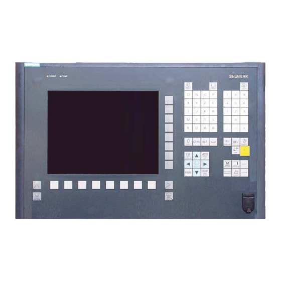
Introduction 1.2 Operator panel fronts Operator panel fronts 1.2.1 Overview Introduction The display (screen) and operation (e.g. hardkeys and softkeys) of the HMI sI operator interface occurs via the panel front. In this example, the OP 010 operator panel front is used to illustrate the components that are available for operating the control and machine tool. -
Page 13: Keys Of The Operator Panel
Introduction 1.2 Operator panel fronts Numerical key group Softkeys Control key group Hotkey group Cursor key group USB interface Menu Select key Menu forward button Machine area button Menu back button References An exact description as well as a view of the other serviceable panel fronts may be found in /BH/, Equipment Manual Panel Components 840D sl/840 Di sl 1.2.2 Keys of the operator panel... - Page 14 Introduction 1.2 Operator panel fronts Function Cursor Input focus/cursor between different fields. Navigate rows or characters. Use the right cursor to open a directory or program in the editor. Use the left cursor to switch to a higher level in the directory tree. SELECT Choose one of a number of options presented.
-
Page 15: Machine Control Panels
1.3.1 Overview The machine tool can be equipped with a machine control panel by Siemens or with a specific machine control panel from the machine manufacturer. You use the machine control panel to initiate actions on the machine tool such as traversing an axis or starting the machining of a workpiece. - Page 16 Introduction 1.3 Machine control panels EMERGENCY STOP button Activate the button in situations where life is at risk. • there is the danger of a machine or workpiece being damaged. • All drives will be stopped with the greatest possible braking torque. Machine manufacturer For additional responses to pressing the Emergency Stop button, please refer to the machine manufacturer's instructions.
- Page 17 Introduction 1.3 Machine control panels Axis keys Selects an axis. Direction keys Select the traversing direction. RAPID Traverse axis in rapid traverse while pressing the direction key. WCS MCS Switches between the workpiece coordinate system (WCS = work) and machine coordinate system (MCS = machine). Spindle control with override switch SPINDLE STOP Stop spindle.
-
Page 18: Operator Interface
Introduction 1.4 Operator interface Operator interface Overview Figure 1-3 Operator interface Active operating area and mode Alarm/message line Program name Channel state and program control Channel operational messages Axis position display in actual value window HMI sl Universal Operating Manual, 11/2006, 6FC5398-6AP10-1BA0... -
Page 19: Status Display
Introduction 1.4 Operator interface Display for active tool T • current feedrate F • current spindle condition • Operating window with program block display Display of G functions, H functions, and input windows for different functions (e.g., program control). Dialog line to provide additional user notes Horizontal softkey bar Vertical softkey bar 1.4.1... - Page 20 Introduction 1.4 Operator interface "Program manager" operating area "Diagnosis" operating area "Start-up" operating area Active mode or submode "Jog" mode "MDA" mode "Auto" mode "Teach In" submode "Repos" submode "Ref Point" submode Alarms and messages Alarm display The alarm numbers are displayed in white lettering on a red background.
- Page 21 Introduction 1.4 Operator interface Machine manufacturer Please also refer to the machine manufacturer's instructions. Third line Display Description Display of channel status. If several channels are present on the machine, the channel name is also displayed. If only one channel is available, only the "Reset" channel status is displayed.
-
Page 22: Actual Value Window
Introduction 1.4 Operator interface See also Channel switchover (Page 36) Touch operation (Page 29) 1.4.2 Actual value window The actual values of the axes and their positions are displayed. WCS/MCS The displayed coordinates are based on either the machine coordinate system or the workpiece coordinate system. -
Page 23: T,F,S Window
Introduction 1.4 Operator interface Display Description Repos offset The distances traversed in manual mode are displayed. This information is only displayed when you are in the "Repos" submode. Footer Display of active zero offsets and transformations as well as the T,F,S values. -
Page 24: Program Block Display
Introduction 1.4 Operator interface Spindle data Display Description Spindle selection, identification with spindle number and main spindle Speed Actual value (when spindle turns, display increases) Setpoint (always displayed, also during positioning) Icon Spindle condition (spindle disable, spindle stop, clockwise rotation, counter- clockwise rotation, positioned, axis mode Override Display as a percentage... -
Page 25: Operation Via Softkeys And Buttons
Introduction 1.4 Operator interface 1.4.5 Operation via softkeys and buttons Operating areas/operating modes The operator interface consists of different windows featuring 8 horizontal and 8 vertical softkeys. You operate the softkeys with the keys next to the softkey bars. You can display a new window or execute functions using the softkeys. HMI sl is divided into 6 operating areas (machine, parameter, program, program manager, diagnosis, startup) and 5 operating modes or submodes (JOG, MDA, AUTO, TEACH In, REF POINT, REPOS). - Page 26 Introduction 1.4 Operator interface General keys and softkeys When the symbol appears to the right of the dialog line on the operator interface, you can change the horizontal softkey bar within an operating area. To do so, press the menu forward key. symbol indicates that you are in the expanded softkey bar.
-
Page 27: Entering Parameters
Introduction 1.4 Operator interface 1.4.6 Entering parameters On setting up the machine and during programming, you must enter values in the white fields for various parameters. Parameters that have a gray input field are automatically calculated. Selecting parameters Some parameters require you to select from a number of options in the input field. Fields of this type do not allow you to type in a value. -
Page 28: Context Menu
Introduction 1.4 Operator interface Press the "INSERT" key. Insertion mode and the pocket calculator are activated. You can navigate within the input field using the "Left cursor" and "Right cursor" keys. Use the "BACKSPACE" or "DEL" key to delete individual characters. Accepting parameters When you have correctly entered all necessary parameters, you can close the window and save your settings. -
Page 29: Touch Operation
Introduction 1.4 Operator interface 1.4.8 Touch operation If you have an operator panel with a touch screen, you can perform the following functions with touch operation: Operating area switchover You can display the operating area menu by touching the display symbol for the active operating area in the status display. - Page 30 Introduction 1.4 Operator interface Proceed as follows Position the cursor on the desired input field. Press the equals sign. The pocket calculator is displayed. Input the arithmetic statement. You can use arithmetic symbols, numbers, and commas. Press the "=" softkey. - OR - Press the "Calculate"...
-
Page 31: Protection Levels
• Tool offsets • Work offsets • Setting data • Program creation / program editing For additional information, please refer to the following documentation: /IHsl/ HMI sl / SINUMERIK 840D sl commissioning manual Softkeys Softkey Protection levels Program Manager operating area... - Page 32 Introduction 1.4 Operator interface Softkey Protection levels HMI sl Universal Operating Manual, 11/2006, 6FC5398-6AP10-1BA0...
-
Page 33: Setting Up The Machine
Setting up the machine Switching on and switching off Start-up When the control starts up, the main screen opens according to the operating mode specified by the machine manufacturer. In general, this is the main screen for the "REF POINT" submode. Machine manufacturer Please also refer to the machine manufacturer's instructions. -
Page 34: Modes Of Operation
Setting up the machine 2.2 Modes of operation Modes of operation 2.2.1 General information You can work in three different operating modes. "JOG" mode "JOG" mode is used for the following preparatory actions: • Reference point approach, i.e. calibration of the position measuring system •... - Page 35 Setting up the machine 2.2 Modes of operation "REPOS" offsets can be displayed in the machine coordinate system (MCS) or workpiece coordinate system (WCS). Selecting "Repos" Press the "REPOS" key. "MDA" mode (Manual Data Automatic) In "MDA" mode, you can enter and execute G code commands non-modally to set up the machine or to perform a single action.
-
Page 36: Channel Switchover
Setting up the machine 2.3 Approaching a reference point 2.2.2 Channel switchover It is possible to switch between channels when several are in use. Since individual channels may be assigned to different mode groups, a channel switchover command is also an implicit mode switchover command. - Page 37 Setting up the machine 2.3 Approaching a reference point Machine manufacturer Please also refer to the machine manufacturer's instructions. Notice If the axes are not in a collision-free position, you must first traverse them to safe positions in "JOG" or "MDA" mode. You must follow the axis motions directly on the machine! Ignore the actual value display until the axes have been referenced! The software limit switches are not active!
-
Page 38: User Agreement
Setting up the machine 2.3 Approaching a reference point 2.3.2 User agreement If you are using Safety Integrated (SI) on your machine, you will need to confirm that the current displayed position of an axis corresponds to its actual position on the machine when you reference an axis. -
Page 39: Settings For The Machine
Setting up the machine 2.4 Settings for the machine Activate the agreement with the "SELECT" key. The selected axis is marked with an "x" meaning "safely referenced" in the "Agreement" column. By pressing the "SELECT" key, you deactivate the agreement again. Settings for the machine 2.4.1 Coordinate system (MCS/WCS) -
Page 40: Work Offsets
Setting up the machine 2.5 Work offsets Work offsets 2.5.1 Overview Following reference point approach, the actual value display for the axis coordinates is based on the machine zero of the machine coordinate system (MCS). The program for machining the workpiece, however, is based on the workpiece zero of the workpiece coordinate system (WCS). - Page 41 Setting up the machine 2.5 Work offsets Work offsets G54 ...G599 Display of all zero offsets activated with G54 - G599, as well as rotation, scaling and mirroring if these are set. You cannot edit these values here. Prog. ZO Display of all additional zero offsets programmed with $P_PFRAME=.
-
Page 42: Displaying And Editing Base Zero Offset
Setting up the machine 2.5 Work offsets 2.5.3 Displaying and editing base zero offset The defined channel-specific and global base offsets, divided into coarse and fine offsets, are displayed for all set-up axes in the "Work offset - Base" window. The rotation, scaling and mirroring are displayed if they are set. -
Page 43: Displaying And Editing Settable Zero Offset
Setting up the machine 2.5 Work offsets 2.5.4 Displaying and editing settable zero offset All settable offsets, divided into coarse and fine offsets, are displayed in the "Zero offset - G54..G599" window. The current active zero offsets are displayed on a green background. The rotation, scaling and mirroring are displayed if they are set. -
Page 44: Displaying And Editing Details Of The Zero Offsets
Setting up the machine 2.5 Work offsets 2.5.5 Displaying and editing details of the zero offsets For each zero offset, you can display and edit all data for all axes. You can also delete zero offsets. For every axis, values for the following data will be displayed: •... -
Page 45: Deleting Zero Offsets
Setting up the machine 2.5 Work offsets Press the "WO +" or "WO -" softkey to select the next or previous offset, respectively, within the selected area ("Active", "Base", "G54 to G599") without first having to switch to the overview window. If you have reached the end of the range (e.g., G599), you will switch automatically to the beginning of the range (e.g., G54). -
Page 46: Manual Mode
Setting up the machine 2.6 Manual mode Manual mode 2.6.1 Traversing the axes You can traverse the axes in manual mode via the Increment or Axis keys or handwheels. During a traverse initiated from the keyboard, the selected axis moves at the programmed setup feedrate. - Page 47 Setting up the machine 2.6 Manual mode Select the "Machine" operating area. Press the "JOG" key. Press keys 1, 10, etc. up to 10000 in order to move the axis in a defined increment. The numbers on the keys indicate the traverse path in micrometers or micro-inches.
-
Page 48: Traversing Axes By A Variable Increment
Setting up the machine 2.6 Manual mode 2.6.3 Traversing axes by a variable increment Proceed as follows Select the "Machine" operating area. Press the "JOG" key. Press the "Settings" softkey. The "Settings for manual operation" window is opened. Enter the desired value for the "Variable increment" parameter. Example Enter 500 for a desired increment of 500 μm (0.5 mm). - Page 49 Setting up the machine 2.6 Manual mode Proceed as follows Select the "Machine" operating area. Press the "JOG" key. Press the menu forward key and the "Settings" softkey. The "Settings for manual operation" window is opened. HMI sl Universal Operating Manual, 11/2006, 6FC5398-6AP10-1BA0...
-
Page 50: Handwheel
Setting up the machine 2.7 Handwheel Handwheel 2.7.1 Handwheel assignment You can traverse the axes in the machine coordinate system (MCS) or in the workpiece coordinate system (WCS) via the handwheel. All axes are provided in the following order for handwheel assignment: •... - Page 51 Setting up the machine 2.7 Handwheel To open the "Axis" selection box using the "INSERT" key, navigate to the desired axis, and press the "INPUT" key. Selecting an axis also activates the handwheel (e.g., "X" is assigned to handwheel no. 1 and is activated immediately). Press the "Handwheel"...
-
Page 52: Mda
Setting up the machine 2.8 MDA In "MDA" mode (Manual Data Automatic mode), you can enter G-code commands block-by- block and immediately execute them for setting up the machine. You can load an MDA program straight from the Program Manager into the MDA buffer. You may also store programs which were rendered or changed in the MDA operating window into any directory of the Program Manager. -
Page 53: Saving An Mda Program
Setting up the machine 2.8 MDA 2.8.2 Saving an MDA program Proceed as follows Select the "Machine" operating area. Press the "MDA" key. The MDA editor opens. Create the MDA program by entering the G-code commands using the operator's keyboard. Press the "Load save"... -
Page 54: Executing An Mda Program
Setting up the machine 2.8 MDA 2.8.3 Executing an MDA program Proceed as follows Select the "Machine" operating area. Press the "MDA" key. The MDA editor opens. Input the desired G-code commands using the operator’s keyboard. Press the "CYCLE START" key. The control executes the input blocks. -
Page 55: Deleting An Mda Program
Setting up the machine 2.8 MDA 2.8.4 Deleting an MDA program You can delete the program created in MDA mode. Proceed as follows Select the "Machine" operating area. Press the "MDA" key. The MDI editor opens. Input the desired G-code commands using the operator’s keyboard. Press the "Delete MDI buffer"... - Page 56 Setting up the machine 2.8 MDA HMI sl Universal Operating Manual, 11/2006, 6FC5398-6AP10-1BA0...
-
Page 57: Machine The Workpiece
Machine the workpiece Starting program execution 3.1.1 Starting and stopping machining During execution of a program, the workpiece is machined in accordance with the programming on the machine. After the program is started in automatic mode, workpiece machining is performed automatically. Prerequisites The following prerequisites must be met before executing a program: •... - Page 58 Machine the workpiece 3.1 Starting program execution Note Starting the program in any operating area If the control is in "AUTO" mode, you can also start the selected program when you are in any operating area. Stopping machining Press the "CYCLE STOP" key. Machining stops immediately.
-
Page 59: Selecting A Program
Machine the workpiece 3.1 Starting program execution 3.1.2 Selecting a program Proceed as follows Select the "Program manager" operating area. The directory overview is opened. Place the cursor on the directory containing the program that you want to select. Press the “INPUT” key - OR - Press the "Cursor right"... -
Page 60: Program Running-In
Machine the workpiece 3.2 Program running-in Program running-in 3.2.1 Executing single blocks When running-in a program, the system can interrupt the machining of the workpiece after each program block, which triggers a movement or auxiliary function on the machine. In this way, you can control the machining result block-by-block during the initial run-through of a program on the machine. -
Page 61: Display Current Program Block
Machine the workpiece 3.3 Display current program block Press the "SINGLE BLOCK" key again, if the machining is not supposed to run block-by-block. The key is deselected again. If you now press the "CYCLE START" key again, the program is executed to the end without interruption. -
Page 62: Correcting Programs
Machine the workpiece 3.4 Correcting programs Proceed as follows Press the menu forward key. A new vertical softkey bar is displayed. Press the "Program levels" softkey. The "Program levels" window appears. Correcting programs As soon as a syntax error in the part program is detected by the control, program execution is interrupted and the syntax error is displayed in the alarm line. -
Page 63: Repositioning Axes
Machine the workpiece 3.5 Repositioning axes Repositioning axes After a program interruption in automatic mode (e.g. after a tool breaks) you can move the tool away from the contour in manual mode. The coordinates of the interrupt position will be saved. The distances traversed in manual mode are displayed in the actual value window. -
Page 64: Starting Execution At A Specific Point
Machine the workpiece 3.6 Starting execution at a specific point Press the "REPOS" key. Select the axes to be traversed one after the other. Press the "+" or "-" key for the relevant direction. The axes are moved to the interrupt position. Starting execution at a specific point 3.6.1 Use block search... -
Page 65: Approaching An Interruption Point Again
Machine the workpiece 3.6 Starting execution at a specific point 3.6.2 Approaching an interruption point again Requirement A program was selected in "AUTO" mode and interrupted during execution with "Reset". Proceed as follows Press the "Interrupt point" softkey. The interruption point is loaded. Press the "Start search"... -
Page 66: Parameters For Block Search
Machine the workpiece 3.6 Starting execution at a specific point Proceed as follows Enter the complete target path in the input fields Press the "Start search" softkey. The search is started. Your specified search mode will be taken into account. The search window closes. - Page 67 Machine the workpiece 3.6 Starting execution at a specific point Search variants Block search mode Description With calculation It is used to be able to approach the contour in any circumstance. - with approach On "Cycle Start", the start position of the target block or the end position of the block before the target block is approached.
-
Page 68: Controlling The Program Run
Machine the workpiece 3.7 Controlling the program run Controlling the program run 3.7.1 Program control You can change the program sequence in the "AUTO" and "MDA" modes. Abbreviation/program Scope control The program is started and executed with auxiliary function outputs and dwell times. In this mode, the axes are not traversed. - Page 69 Machine the workpiece 3.7 Controlling the program run Display / response of active program controls: If a program control is activated, the abbreviation of the corresponding function appears in the status display as response. Proceed as follows Select the "Machine" operating area. Press the "AUTO"...
-
Page 70: Skip Blocks
Machine the workpiece 3.7 Controlling the program run 3.7.2 Skip blocks It is possible to skip program blocks, which are not to be executed every time the program runs. The skip blocks are identified by placing a "/" (forward slash) or "/x (x = number of skip level) character in front of the block number. -
Page 71: Editing Programs
Machine the workpiece 3.8 Editing programs Press the "AUTO" or "MDA" key. Press the "Prog. cntrl." and "Skip blocks" softkeys. The "Program control" window appears and shows a list of block levels. Editing programs 3.8.1 Overview With the editor, you are able to render, supplement, or change part programs. Note The maximum block length is 512 characters. -
Page 72: Searching In Programs
Machine the workpiece 3.8 Editing programs Note Please note that the changes to programs stored in the NC memory take immediate effect. You can exit the editor only after you have saved the changes. This applies for all local drives that allow editing. 3.8.2 Searching in programs You can use the search function to quickly arrive at points where you would like to make... -
Page 73: Replacing Program Text
Machine the workpiece 3.8 Editing programs Further search options Softkey Function The cursor is set to the first character in the program. The cursor is set to the last character in the program. 3.8.3 Replacing program text You can find and replace text in one step. Requirement The desired program is opened in the editor. -
Page 74: Copying/Pasting/Deleting Program Blocks
Machine the workpiece 3.8 Editing programs Press the "Continue search" softkey if the text located during the search should not be replaced. - OR - Press the "Cancel" softkey when you want to cancel the search. 3.8.4 Copying/pasting/deleting program blocks Requirement The program is opened in the editor. -
Page 75: Renumbering Programs
Machine the workpiece 3.8 Editing programs 3.8.5 Renumbering programs You can modify the block numbering of programs opened in the editor at a later point in time. Requirement The program is opened in the editor. Proceed as follows Press the ">>" softkey. A new vertical softkey bar appears. - Page 76 Machine the workpiece 3.8 Editing programs Settings Description Increment Defines the increment used for the block numbers. The field is only editable when "Yes" is available under "Number automatically". Display hidden lines Hidden lines marked with "*HD" (hidden) will be displayed. Display block end as The "LF"...
-
Page 77: Display G And Auxiliary Functions
Machine the workpiece 3.9 Display G and auxiliary functions Display G and auxiliary functions 3.9.1 Selected G functions 16 selected G groups are displayed in the "G function" window. Within a G group, the G function currently active in the control is displayed. Some G codes (e.g. - Page 78 Machine the workpiece 3.9 Display G and auxiliary functions Proceed as follows Select the "Machine" operating area. Press the "JOG", "AUTO", or "MDA" key. Press the "G functions" softkey. The "G functions" window is opened. Press the "G functions" softkey again to hide the window again. The G groups selection displayed in the "G functions"...
-
Page 79: All G Functions
Machine the workpiece 3.9 Display G and auxiliary functions 3.9.2 All G functions All G groups and their group numbers are listed in the "G functions" window. Within a G group, only the G function currently active in the control is displayed. Additional information in the footer The following additional information is displayed in the footer: •... -
Page 80: Auxiliary Functions
Machine the workpiece 3.10 Status of synchronized actions 3.9.3 Auxiliary functions Auxiliary functions include M and H functions preprogrammed by the machine manufacturer, which pass parameters to the PLC to trigger reactions defined by the manufacturer. Displayed auxiliary functions Up to 5 current M functions and 3 H functions are displayed in the "Auxiliary functions" window. - Page 81 Machine the workpiece 3.10 Status of synchronized actions Synchronization types Synchronization types Description ID=n Modal synchronized actions in automatic mode, local to program; n = 1 to IDS=n Static synchronized actions in all modes, n = 1 to 254 Without ID/IDS Non-modal synchronized actions in automatic mode Note Numbers ranging from 1 to 254 can only be assigned one time, irrespective of the...
-
Page 82: Settings For Automatic Mode
Machine the workpiece 3.11 Settings for automatic mode 3.11 Settings for automatic mode 3.11.1 Defining the dry run feedrate Before machining a workpiece, test the program without moving the machine axes. This allows for early detection of programming errors. For this test, you can use a dry run feedrate that you have defined. -
Page 83: Teaching In Programs
Teaching in programs Overview The "Teach in" function can be used to edit programs in the "AUTO" and "MDA" modes. You can create and modify simple traversing blocks. You traverse the axes manually to specific positions in order to implement simple machining sequences and make them reproducible. -
Page 84: Inserting Blocks
Teaching in programs 4.3 Inserting blocks Note All defined axes are "taught in" in the first teach-in block. In all additional teach-in blocks, only axes modified by axis traversing or manual input are "taught in". If you exit teach-in mode, this sequence begins again. Operating mode or operating area switchover If you switch to another operating mode or operating area in teach-in mode, the position changes will be canceled and teach-in mode will be cleared. -
Page 85: Teach-In Via Windows
Teaching in programs 4.3 Inserting blocks Press the "Teach position" softkey. A new program block with the current actual position values will be created. 4.3.1 Teach-in via Windows 4.3.1.1 General information The cursor must be positioned on an empty line. The windows for pasting program blocks contain input and output fields for the actual values in the WCS. -
Page 86: Teach In Rapid Traverse G0
Teaching in programs 4.3 Inserting blocks Press the softkeys "Rap. tra. G0", "Straight line G1", or Circ. interm. pos. CIP" and "Circ. end pos. CIP". The relevant windows with the input fields are displayed. Traverse the axes to the relevant position. Press the "Accept"... -
Page 87: Teaching In Circle Intermediate And Circle End Point Cip
Teaching in programs 4.3 Inserting blocks 4.3.1.4 Teaching in circle intermediate and circle end point CIP Enter the intermediate and end positions for the circle interpolation CIP. You teach-in each of these separately in a separate block. The order in which you program these two points is not specified. - Page 88 Teaching in programs 4.3 Inserting blocks Proceed as follows Select the "Machine" operating area. Press the "AUTO" or "MDA" key. Press the "TEACH IN" key. Press the "Teach prog." softkey. Press the ">>" and "ASPLINE" softkeys. The "Akima-spline" window opens with the input fields. Traverse the axes to the required position and if necessary, set the transition type for the starting point and end point.
-
Page 89: Input Parameters For Teach-In Blocks
Teaching in programs 4.3 Inserting blocks 4.3.2 Input parameters for teach-in blocks Parameters for teach-in of position and teach-in of G0, G1, and circle end position CIP parameters Description Approach position in X direction Approach position in Y direction Approach position in Z direction Feedrate (mm/r;... -
Page 90: Changing Blocks
Teaching in programs 4.4 Changing blocks Transition behavior at the beginning and end of the spline curve The following motion parameters are offered: Parameters Description Start BAUTO Automatic calculation BNAT Curvature is zero or natural BTAN Tangential EAUTO Automatic calculation ENAT Curvature is zero or natural ETAN... - Page 91 Teaching in programs 4.4 Changing blocks Proceed as follows Select the "Machine" operating area. Press the "AUTO" or "MDA" key. Press the "TEACH IN" key. Press the "Teach prog." softkey. Click the program block to be edited. Press the relevant softkey "Teach position, "Rap. tra. G0", "Straight line G1", or "Circ.
-
Page 92: Block Selection
Teaching in programs 4.5 Block selection Block selection You have the option of setting the interrupt pointer to the current cursor position. The next time the program is started, processing will resume from this point. With teach-in, you can also change program areas that have already been executed. This automatically disables program processing. -
Page 93: Deleting Blocks
Teaching in programs 4.6 Deleting blocks Deleting blocks You have the option of deleting a program block entirely. Requirement "AUTO" mode: The program to be processed is selected. Proceed as follows Select the "Machine" operating area. Press the "AUTO" or "MDA" key. Press the "TEACH IN"... -
Page 94: Parameter Settings
Teaching in programs 4.7 Parameter settings Parameter settings 4.7.1 Settings for teach-in In the "Settings" window, you define which axes are to be included in the teach-in block and whether motion-type and continuous-path mode parameters are to be provided. Proceed as follows Select the "Machine"... -
Page 95: Setting Data
Setting data Specify working area limitations The "Working area limitation" function can be used to limit the range within which a tool can traverse in all channel axes. These commands allow you to set up protection zones in the working area which are out of bounds for tool movements. In this way, you are able to restrict the traversing range of the axes in addition to the limit switches. - Page 96 Setting data 5.1 Specify working area limitations Note A list of all setting data is available in the "Start-up" operating area. HMI sl Universal Operating Manual, 11/2006, 6FC5398-6AP10-1BA0...
-
Page 97: User Data
User data Introduction The defined user data may be displayed in lists. The following variables can be defined: • Data parameters (R parameters) • Global user data (GUD) is valid in all programs • Local user data (LUD) is valid in one program •... -
Page 98: R Parameters
User data 6.2 R parameters Searching for user data You may search for user data within the lists using any character string. Refer to the "Defining and activating user data" section to learn how to edit displayed user data. R parameters R parameters (arithmetic parameters) are channel-specific variables that you can use within a G code program. -
Page 99: Displaying Global User Data (Gud)
User data 6.3 Displaying global user data (GUD) Delete R variables Press the ">>" and "Delete area" softkeys. The "Delete R parameters" window appears. Enter the R parameter(s) whose channel-specific values you would like to delete and press the "OK" softkey. - OR - Press the "Delete all"... - Page 100 User data 6.3 Displaying global user data (GUD) File name Description MGUD.DEF Definitions for global machine manufacturer data UGUD.DEF Definitions for global user data GUD4.DEF User-definable data GUD8.DEF, GUD9.DEF User-definable data Proceed as follows Select the "Parameter" operating area. Press the "User variable" softkey. Press the "Global GUD"...
-
Page 101: Displaying Channel Guds
User data 6.4 Displaying channel GUDs Displaying channel GUDs Channel-specific user data Like the GUDs, channel-specific user data are applicable in all programs for each channel. However, unlike GUDs, they have specific values. Definition A channel-specific GUD variable is defined with the following: •... -
Page 102: Displaying Local User Data (Lud)
User data 6.5 Displaying local user data (LUD) Press the "Continue" softkey and the "GUD7" to "GUD9" softkeys if you want to display GUD 7 to GUD 9 of the channel-specific user data. Displaying local user data (LUD) Local user data LUDs are only valid in the program or subroutine in which they were defined. -
Page 103: Displaying Program User Data (Pud)
User data 6.6 Displaying program user data (PUD) Displaying program user data (PUD) Program-global user data PUDs are global part program variables (Program User Data). PUDs are valid in all main programs and subroutines, where they can also be written and read. Proceed as follows Select the "Parameter"... -
Page 104: Defining And Activating User Data
User data 6.8 Defining and activating user data Press the "Search" softkey. The "Search for R parameters" or "Search for user data" window opens. Enter the desired search term and press "OK". The cursor is automatically positioned on the the R parameter or user data you are searching for, if they exist. - Page 105 User data 6.8 Defining and activating user data Press the "Exit" softkey to close the editor. Activating user data Press the "Activate" softkey. A prompt is displayed. Select whether the current values in the definition files should be retained - OR - Select whether the current values in the definition files should be deleted.
- Page 106 User data 6.8 Defining and activating user data HMI sl Universal Operating Manual, 11/2006, 6FC5398-6AP10-1BA0...
-
Page 107: Tool Management
Tool management Overview Various tools are used for machining workpieces. Lists for tool management HMI sl provides the "Tool list", "Tool wear list", "OEM tools" and "Magazine" windows for managing your tools. Tool management supports several magazines. The active magazine is displayed in the title line of each list. -
Page 108: Tool List
Tool management 7.2 Tool list Tool list The Tool list shows all tools in the magazines and the NC memory. Each tool is uniquely identified by a name and a duplo number. Tool parameters Column heading Description Location Magazine/location number Spindle location as an icon •... -
Page 109: Additional Data For Tools
Machine manufacturer Please also refer to the machine manufacturer's instructions. References For a description of configuration options, refer to the HMI sl / SINUMERIK 840D sl commissioning manual Proceed as follows Select the "Parameter" operating area. Press the "Tool list" softkey. -
Page 110: Entering New Tools In The Tool List
Tool management 7.2 Tool list 7.2.2 Entering new tools in the tool list A number of tool types are available when you create a new tool. The tool type determines which geometry data are required and how they will be computed. Possible tool types Figure 7-1 Example of Favorites list... - Page 111 Tool management 7.2 Tool list Figure 7-4 Available tools in the "New tool - special tools" window When creating a new tool, the "New tool - favorites" window offers you a number of select tool types, known as "favorites". If you do not find the desired tool type in the favorites list, then select the milling, drilling or special tool via the corresponding softkeys.
-
Page 112: Managing Several Cutting Edges
• Size of tool References: For a description of configuration options, refer to the HMI sl / SINUMERIK 840D sl commissioning manual 7.2.3 Managing several cutting edges In the case of tools with more than one cutting edge, a separate set of offset data is assigned to each cutting edge. -
Page 113: Deleting Cutting Edges
Tool management 7.2 Tool list Press the "Edges" softkey in the "Tool list". Press the "New cuttgEdge" softkey. A new data set is stored in the list. The edge number is incremented by 1 and the offset data are assigned the values of the edge on which the cursor is positioned. Enter the offset data for the second cutting edge. -
Page 114: Deleting Tools
Tool management 7.2 Tool list 7.2.5 Deleting tools Tools that are no longer in use can be deleted from the tool list for a clearer overview. Proceed as follows Select the "Parameter" operating area. Press the "Tool list" softkey. Place the cursor on the tool that you would like to delete. Press the "Delete tool"... - Page 115 Tool management 7.2 Tool list Proceed as follows Select the "Parameter" operating area. Press the "Tool list" softkey. Place the cursor on the tool that you want to load into the magazine (if the tools are sorted according to magazine location number you will find it at the end of the tool list).
-
Page 116: Selecting A Magazine
Tool management 7.2 Tool list Unloading tools Place the cursor on the tool that you would like to unload from the magazine and press the "Unload" softkey. Select the required load point in the "Load point selection" window. Confirm your selection with "OK". - OR - Undo your selection with "Cancel". - Page 117 The magazine selection behavior with multiple magazines can be configured in different ways. Machine manufacturer Please also refer to the machine manufacturer's instructions. References For a description of configuration options, refer to the HMI sl / SINUMERIK 840D sl commissioning manual HMI sl Universal Operating Manual, 11/2006, 6FC5398-6AP10-1BA0...
-
Page 118: Tool Wear
Tool management 7.3 Tool wear Tool wear Tools that are in use for long periods are subject to wear. You can measure this wear and enter it in the tool wear list. The control then takes this information into account when calculating the tool length or radius compensation. -
Page 119: Reactivating Tools
Tool management 7.3 Tool wear Symbols in the wear list Icon / Description Identification Type Red "X" The tool is disabled. Yellow triangle The prewarning limit has been reached. Activating tool monitoring You can automatically monitor the tools' working times via the workpiece count, tool life or wear. -
Page 120: Tool Data Oem
Machine manufacturer Please also refer to the machine manufacturer's instructions. References HMI sl / SINUMERIK 840D sl commissioning manual Multiple load points If you have configured several loading points for a magazine, then the "Load point selection" window appears after pressing the "Load" softkey. -
Page 121: Magazine
Tool management 7.5 Magazine Magazine Tools are displayed with their magazine-related data in the magazine list. Here, you can take specific actions relating to the magazines. Individual magazine locations can be location-coded or disabled for existing tools. Tool parameters Column heading Description Location Magazine location number... -
Page 122: Position Magazine
Tool management 7.5 Magazine 7.5.1 Position magazine You can position magazine locations directly on the loading point. Proceed as follows Select the "Parameter" operating area. Press the "Magazine” softkey. Place the cursor on the magazine location that you want to position onto the load point. - Page 123 Tool management 7.5 Magazine Proceed as follows Select the "Parameter" operating area. Press the "Magazine” softkey. Position the cursor on the tool that you wish to relocate to a different magazine location. Press the "Relocate" softkey. The "... relocate from location ... to ..." window appears on the screen. The "...
-
Page 124: Sorting Tool Management Lists
Tool management 7.6 Sorting tool management lists Sorting tool management lists When you are working with many tools, with large magazines or several magazines, it is useful to display the tools sorted according to different criteria. Then you will be able to find a specific tool more easily in the lists. -
Page 125: Program Management
Program management Overview Place all programs that you would like to execute in the NC. You can access these programs at any time via the Program Manager for execution, editing, copying, or renaming. Programs that you no longer require can be deleted to release their storage space. -
Page 126: Nc Memory
Program management 8.1 Overview Structure of the directories In the overview, the symbols in the left-hand column have the following meaning: Folder Program The directories and programs are always listed complete with the following information: • Name The name can contain up to 24 characters + dot + 3-character extension (e.g., MPF). Permissible characters include all upper-case letters (no umlauts), numbers, and underscores. -
Page 127: Local Drive
Program management 8.2 Opening and closing a program 8.1.2 Local drive The workpieces, main programs and subroutines stored in HMI sI are displayed. You can create any number of subdirectories here, in which to store any files (e.g., text files with notes). - Page 128 Program management 8.2 Opening and closing a program Proceed as follows Select the "Program manager" operating area. Select the desired storage location and position the cursor on the program that you would like to edit. Press the "Open" softkey. - OR - Press the "INPUT"...
-
Page 129: Executing A Program
Program management 8.3 Executing a program Executing a program When you select a program for execution, the control automatically switches to the "Machine" operating area. Program selection Select the workpieces (WPD), main programs (MPF) or subroutines (SPF) by placing the cursor on the desired program or workpiece. -
Page 130: Creating Directories/Programs
Program management 8.4 Creating directories/programs If the selected program is already opened in the "Program" operating area, press the " NC Execute" softkey. Press the "CYCLE START" key. Execution of the workpiece is started. Note Only workpieces/programs located in the NCK memory can be selected for execution. Creating directories/programs 8.4.1 Creating a new directory... -
Page 131: Creating A New Workpiece
Program management 8.4 Creating directories/programs Press the "New" and "Directory" softkeys. The "New directory" window appears. Enter the desired directory name and press the "OK" softkey. The new directory is displayed. 8.4.2 Creating a new workpiece You can set up various types of files such as main programs, initialization files, tool offsets, etc. -
Page 132: Creating A New G Code Program
Program management 8.4 Creating directories/programs Enter the desired workpiece name, select a template, if necessary, and press the "OK" softkey. The name can contain up to 28 characters (name + dot. + 3-character extension). You can use any letters (except umlauts), digits or the underscore symbol (_). -
Page 133: Storing Any New File
Program management 8.4 Creating directories/programs Enter the desired program name and press the "OK" softkey. The program name can contain up to 28 characters (name + dot. + 3- character extension). You can use any letters (except umlauts), digits or the underscore symbol (_). -
Page 134: Selecting Several Directories/Programs
Program management 8.5 Selecting several directories/programs Selecting several directories/programs You can select several files and directories for further processing. When you select a directory, all directories and files located beneath it are also selected. Note If you have selected several directories and one of them closes, then selection of the directory and all of the files contained therein is cancelled. - Page 135 Program management 8.5 Selecting several directories/programs Canceling a selection By reselecting an element, the existing selection is cancelled. Selecting via keys Key combination Description Renders or expands a selection. You can only select individual elements. Renders a consecutive selection. A previously existing selection is cancelled. Selecting with the mouse Key combination Description...
-
Page 136: Copying And Pasting Directories/Programs
Program management 8.6 Copying and pasting directories/programs Copying and pasting directories/programs To create a new directory or program that is similar to an existing program, you can save time by copying the old directory or program and only changing selected programs or program blocks. - Page 137 Program management 8.6 Copying and pasting directories/programs Proceed as follows Select the "Program manager" operating area. Choose the desired storage location and position the cursor on the file or directory which you would like to copy. Press the "Copy" soft key. Select the directory in which you want to paste your copied directory/program.
-
Page 138: Deleting Directories/Programs
Program management 8.7 Deleting directories/programs Deleting directories/programs Delete programs or directories from time to time that you are no longer using to maintain a clearer overview of your data management. Back up the data beforehand, if necessary, on an external data medium (e.g., USB FlashDrive) or on a network drive. Please note that when you delete a directory, all programs, tool data and zero point data and subdirectories that this directory contains are deleted. -
Page 139: Renaming File And Directory Properties
Program management 8.8 Renaming file and directory properties Renaming file and directory properties Information on directories and files can be displayed in the "Properties for ..." window. Information on the creation date is displayed near the file's path and name. You can change names. - Page 140 Program management 8.9 Templates Storage location for templates The templates used to create part programs or workpieces can be stored in the following directories: HMI Data/Templates/Manufacturer/Part programs or Workpieces HMI Data/Templates/User/Part programs or Workpieces Proceed as follows Select the "Program manager" operating area. Press the menu forward key and the "System data"...
-
Page 141: Backing Up Data
You can select data from the user/manufacturer archives, the CF card (but not from the Siemens folder), the NCU, the local drive, and the configured network or USB drives. Possible storage locations are the "User" and "Manufacturer" subfolders in the "Archives"... -
Page 142: Importing Data
Program management 8.10 Backing up data If you want to back up several files or directories, press the "Select" softkey and, using the cursor or the mouse, select the required directories or files. Press the ">>" and "Generate archive" softkeys. The "Generate archive: Select archiving"... - Page 143 Program management 8.10 Backing up data Press the "Read in" softkey. Press the "OK" or "Overwrite all" softkey to overwrite existing files. - OR - Press the "No overwriting" softkey if you do not want to overwrite existing files. - OR - Press the "Skip"...
- Page 144 Program management 8.10 Backing up data HMI sl Universal Operating Manual, 11/2006, 6FC5398-6AP10-1BA0...
-
Page 145: Ht8
The mobile SINUMERIK HT8 handheld terminal combines the functions of an operator panel and a machine control panel. It is therefore suitable for visualization, operation, teach in, and programming at the machine. Customer keys (user-defined) Traversing keys User menu key Handwheel (optional) Operation The 7.5 TFT color display provides touch operation. - Page 146 References For more information about connection and start-up of the HT8, see the following references: CNC Commissioning: SINUMERIK 840D sl Operator Components and Networking Customer keys The four customer keys are freely assignable and can be set up customer-specifically by the machine manufacturer.
-
Page 147: Traversing Keys
Handwheel The HT8 is available with a hand wheel. References For information about connecting the hand wheel, refer to: CNC Commissioning: SINUMERIK 840D sl Operator Components and Networking See also Channel switchover (Page 36) Traversing keys The traversing keys are not labeled. However, you can display a label for the keys in place of the vertical softkey bar. - Page 148 9.1 Traversing keys Showing and hiding You can link the showing and hiding of the label to activation of the enabling button, for example. In this case, the traversing keys are displayed when you press the enabling button. If you release the enabling button, the traversing keys are hidden again. Machine manufacturer Please also refer to the machine manufacturer's instructions.
-
Page 149: Machine Control Panel Menu
9.2 Machine control panel menu Machine control panel menu Here you select keys from the machine control panel which are reproduced by the software by touch operation of the relevant softkeys. See chapter "Controls on the machine control panel" for a description of the individual keys. Showing and hiding The user menu key "U"... -
Page 150: Virtual Keyboard
9.3 Virtual keyboard Softkeys on the machine control panel menu Available softkeys: "Machine" softkey Select the "Machine" operating area "[VAR]" softkey Select the axis feedrate in the variable increment "Single Block" Switch single block execution on/off softkey "WCS MCS" Switch between WCS and MCS softkey "Back"... - Page 151 9.3 Virtual keyboard Positioning of the virtual keyboard You can position the virtual keyboard anywhere in the window by depressing the empty bar next to the "Close window" symbol with your finger or a stylus and moving it back and forth. Special keys on the virtual keyboard Num: Reduces the virtual keyboard to the number block.
-
Page 152: Calibrating The Touch Panel
9.4 Calibrating the touch panel Calibrating the touch panel It is necessary to calibrate the touch panel upon first connection to the control. Note Recalibration If the operation is not exact, then redo the calibration. Proceed as follows Press the "Back" key and the "MENU SELECT" key at the same time to start the TCU service screen. -
Page 153: Pcu 321
PCU 321 10.1 Overview The SINUMERIK PCU 321 is a powerful computer unit of the same type of construction as the SIMATIC S7-300 allowing simple installation on an S7 mounting rail. Figure 10-1 View of a PCU 321 (closed) (1) Rating plate (2) Front door (to fold open) (3) Mode switch (4) LEDs... -
Page 154: Basic Functions
PCU 321 10.2 Basic Functions Operating Component software HMI Pro sl OP 08T, OP 012, OP 12T, OP 015A, OP 015AT, TP 015A, TP 015AT HMI sl OP 08T, OP 010, OP 010C, OP 010S, OP 012, OP 012T, OP 015, OP 015A, OP 015AT, TP 015A, TP 015AT 10.2 Basic Functions... - Page 155 PCU 321 10.2 Basic Functions Figure 10-2 Program manager with expansion of softkey bar Using the arrow keys or the mouse, you can select the data source. Via the vertical softkeys, you are offered functions for processing the data. For a more detailed description of the functions, please refer to Chapter 9 in the Operating Manual.
- Page 156 PCU 321 10.2 Basic Functions Diagnostics operating area The alarm list, the variable overview (PLC) and the version are displayed in the operating ares Diagnostics. Figure 10-3 Diagnostics operating area If erraneous states are detected when operating the PCU 321, an alarm is generated. It consists of an alarm number and an error text describing the cause of the error.
-
Page 157: Alarm, Error, And System Messages
Alarm, error, and system messages 11.1 Displaying alarms If faulty conditions are recognized in the operation of the machine, then an alarm will be generated and, if necessary, the machining will be interrupted. The error text that is displayed together with the alarm number gives you more detailed information on the error cause. - Page 158 Alarm, error, and system messages 11.1 Displaying alarms Select the "Diagnosis" operating area. Press the "Alarm list” softkey. The "Alarms" window appears. Position the cursor on an alarm. Press the "Delete HMI alarm" softkey to cancel the alarm. - OR - Press the "Acknowl.
-
Page 159: Displaying Messages
Alarm, error, and system messages 11.2 Displaying messages 11.2 Displaying messages PLC and part program messages may be issued during machining. These message will not interrupt the program execution. Messages provide information with regard to a certain behavior of the cycles and with regard to the progress of machining and are usually kept beyond a machining step or until the end of the cycle. -
Page 160: Displaying Version Data
Alarm, error, and system messages 11.3 Displaying version data 11.3 Displaying version data All system software components are provided with their corresponding version data in the "Version data" window. You may save the version data. Version displays saved as text files can be further processed as required or sent to the hotline in the event of an error. -
Page 161: Appendix
Appendix Correction sheet - fax template Should you come across any printing errors when reading this publication, please notify us on this sheet. Suggestions for improvement are also welcome. HMI sl Universal Operating Manual, 11/2006, 6FC5398-6AP10-1BA0... -
Page 162: Overview
Appendix A.2 Overview Overview HMI sl Universal Operating Manual, 11/2006, 6FC5398-6AP10-1BA0... -
Page 163: Index
Index Workpiece, 131 Current block display, 24, 61 Actual value display, 22 Any file Create, 133 Data Archives Backing up, 141 Creating, 141 Importing, 142 Automatic mode Data block (SB2), 60 Specifying settings, 82 Deleting Auxiliary functions Programs, 138 H functions, 80 Directories M functions, 80 Copying, 136... - Page 164 Index G Functions Display all G groups, 79 Opening Global user data, 99 Programs, 127 Operating area Changing, 25 Operating mode H functions, 80 AUTO, 35 Handheld terminal 8, 145 change, 25 Handwheel JOG, 34 Assigning, 50 MDA, 35 Highlight Operator panel Programs, 134 Keys, 13...
- Page 165 Index Creating, 139 Storage locations, 140 R parameters, 98 Tool Reference point approach, 36 Relocating, 122 Repositioning, 63 Tool data Actual value window, 23 Tool list, 108 Tool management, 107 SB1, 60 Sorting lists, 124 SB2, 60 Tool types, 110 SB3, 60 Tools Screen layout, 18...
- Page 166 HMI sl Universal Operating Manual, 11/2006, 6FC5398-6AP10-1BA0...