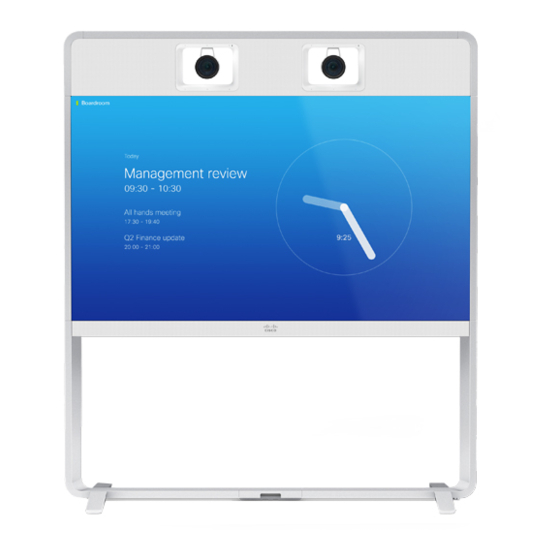
Cisco TelePresence MX700 Installation Manual
Single camera mounted on the wall
Hide thumbs
Also See for TelePresence MX700:
- Reference manual (241 pages) ,
- Administrator's manual (141 pages) ,
- Installation manual (32 pages)
Quick Links
See also:
Administrator's Manual, Reference Manual

Related Manuals for Cisco TelePresence MX700


Summary of Contents for Cisco TelePresence MX700
-
Page 1: Installation Guide
Installation guide for Cisco TelePresence MX700 Single Camera mounted on the wall 78-100254-03A0 | 2016 JUNE | © 2016 Cisco Systems, Inc. All rights reserved. http://www.cisco.com/go/mx-docs... -
Page 2: Safety Information
The wall-mounted system must be installed by qualified safety information for the video system, personnel, in accordance with state and local building http://www.cisco.com/go/mx-docs regulations. 78-100254-03A0 | 2016 JUNE | © 2016 Cisco Systems, Inc. All rights reserved. Page 2... - Page 3 Shows which boxes are inside. Tools and screws are in this box. Lift off box L/M. Lay box A flat on the floor and remove the lid. 78-100254-03A0 | 2016 JUNE | © 2016 Cisco Systems, Inc. All rights reserved. Page 3...
- Page 4 Tool: Allen key, 4 mm PT4x10, pan Tool: Torx T20 M4x8, pan Tool: Allen key, 2.5 mm Tools Allen key, 4 mm Allen key, 2.5 mm Torx T20 78-100254-03A0 | 2016 JUNE | © 2016 Cisco Systems, Inc. All rights reserved. Page 4...
- Page 5 Installation guide for Cisco TelePresence MX700 Single camera - Wall mount Assemble lower frame A, B 8 × M6x12, countersunk Six screws from the back and two from the top. 78-100254-03A0 | 2016 JUNE | © 2016 Cisco Systems, Inc. All rights reserved. Page 5...
- Page 6 Installation guide for Cisco TelePresence MX700 Single camera - Wall mount Fasten center bracket 2 × M6x12, pan 78-100254-03A0 | 2016 JUNE | © 2016 Cisco Systems, Inc. All rights reserved. Page 6...
- Page 7 - The camera gives an elevated view of the room. This view is not optimal for video conferencing. Further information: http://www.cisco.com/go/projectworkplace 2D CAD drawings with measurements: http://www.cisco.com/go/mx-docs (Technical References) 78-100254-03A0 | 2016 JUNE | © 2016 Cisco Systems, Inc. All rights reserved. Page 7...
- Page 8 You may use the lower frame to check that the two brackets are level. Follow the same instructions for mounting the left wall bracket. Refer to step 3. 78-100254-03A0 | 2016 JUNE | © 2016 Cisco Systems, Inc. All rights reserved. Page 8...
- Page 9 (screws and mounting hardware not provided; not shown in illustration). Mount spacers onto the wall brackets. Fasten each spacer with two screws (not provided; not shown in illustration). 78-100254-03A0 | 2016 JUNE | © 2016 Cisco Systems, Inc. All rights reserved. Page 9...
- Page 10 Installation guide for Cisco TelePresence MX700 Single camera - Wall mount Fasten lower frame 4 × M6x12, pan 78-100254-03A0 | 2016 JUNE | © 2016 Cisco Systems, Inc. All rights reserved. Page 10...
- Page 11 Push the support bracket Tighten the screws and tight against the back plate check that the clamp is of the monitor. properly fastened. 78-100254-03A0 | 2016 JUNE | © 2016 Cisco Systems, Inc. All rights reserved. Page 11...
- Page 12 78-100254-03A0 | 2016 JUNE | © 2016 Cisco Systems, Inc. All rights reserved. Page 12...
- Page 13 Tighten the wing nuts on both sides. They are accessed from the sides of the monitor. Front view Front view 78-100254-03A0 | 2016 JUNE | © 2016 Cisco Systems, Inc. All rights reserved. Page 13...
- Page 14 Two M6x100 screws and their brackets, from underneath. Left side of the Right side of the Then, tighten all screws. monitor, viewed monitor, viewed from underneath from underneath 78-100254-03A0 | 2016 JUNE | © 2016 Cisco Systems, Inc. All rights reserved. Page 14...
- Page 15 Front view Do not let go of the monitor before it is securely placed on the lower frame. Front view 78-100254-03A0 | 2016 JUNE | © 2016 Cisco Systems, Inc. All rights reserved. Page 15...
- Page 16 Two M6x100 screws and their brackets, from from underneath underneath. Make sure that the power switch next to the socket is in its ON position. Then, tighten all screws. 78-100254-03A0 | 2016 JUNE | © 2016 Cisco Systems, Inc. All rights reserved. Page 16...
- Page 17 Installation guide for Cisco TelePresence MX700 Single camera - Wall mount Remove support handles Unscrew the screws (4 × M4x8) and remove the support handles. 78-100254-03A0 | 2016 JUNE | © 2016 Cisco Systems, Inc. All rights reserved. Page 17...
- Page 18 Place the joining bracket in the channel. Make sure that it aligns with the channel at top. Push down the lever to 7 × M6x12, pan horizontal position. 78-100254-03A0 | 2016 JUNE | © 2016 Cisco Systems, Inc. All rights reserved. Page 18...
- Page 19 Reach the screw hole through the monitor’s lifting handle. Repeat this step for the other cover. 2 × M6x12, pan (one for each cover) 78-100254-03A0 | 2016 JUNE | © 2016 Cisco Systems, Inc. All rights reserved. Page 19...
- Page 20 Installation guide for Cisco TelePresence MX700 Single camera - Wall mount Fasten cable bridge 2 × M6x12, pan 78-100254-03A0 | 2016 JUNE | © 2016 Cisco Systems, Inc. All rights reserved. Page 20...
- Page 21 Lower the back cover toward the system. The cover snaps to magnets. Rear view, for illustration purposes. Mount from front. 78-100254-03A0 | 2016 JUNE | © 2016 Cisco Systems, Inc. All rights reserved. Page 21...
- Page 22 HDMI (step 21) HDMI (step 19) 3–5 (step 22) USB, type B (step 19) Power (step 21) 5 × Loudspeaker cables Ethernet (step 21) 1–5 (step 22) 78-100254-03A0 | 2016 JUNE | © 2016 Cisco Systems, Inc. All rights reserved. Page 22...
- Page 23 Connect cables to right monitor and PoE injector SWITCH Ethernet Power over Ethernet injector COLOR HDMI DO NOT CALIBRATION REMOVE HDMI USB (type B) Right monitor connector panel 78-100254-03A0 | 2016 JUNE | © 2016 Cisco Systems, Inc. All rights reserved. Page 23...
-
Page 24: Mount Camera
Fasten the stud to the top profile with one screw from above. Repeat this step for the left side. 78-100254-03A0 | 2016 JUNE | © 2016 Cisco Systems, Inc. All rights reserved. Page 24... - Page 25 Enter the camera cover in the clips 2 × M4x8, pan at the bottom, and align it with the back panels. The cover snaps to magnets. 78-100254-03A0 | 2016 JUNE | © 2016 Cisco Systems, Inc. All rights reserved. Page 25...
- Page 26 Installation guide for Cisco TelePresence MX700 Single camera - Wall mount Connect camera cables DAISY VISCA CHAIN HDMI Power Ethernet Camera connector panel 78-100254-03A0 | 2016 JUNE | © 2016 Cisco Systems, Inc. All rights reserved. Page 26...
- Page 27 Fasten with one screw. Enter the loudspeaker onto the speaker clip. Make sure that no cables are pinched. 8 × PT4x10 (one for each loudspeaker) 78-100254-03A0 | 2016 JUNE | © 2016 Cisco Systems, Inc. All rights reserved. Page 27...
-
Page 28: Connect External Cables
Codec connector panel CAT 5e, shielded Ethernet cable, 5 m. Two presentation cables are provided: HDMI ↔ HDMI; and DVI/Euroblock ↔ VGA/mini jack. 78-100254-03A0 | 2016 JUNE | © 2016 Cisco Systems, Inc. All rights reserved. Page 28... - Page 29 The Ethernet socket is behind the lid at the rear of Touch 10. Use one of the provided PoE rated CAT 5e Ethernet cables, 12.5 or 4 m, flat. 78-100254-03A0 | 2016 JUNE | © 2016 Cisco Systems, Inc. All rights reserved. Page 29...
-
Page 30: Start Up The System
Getting Started articles for room systems. Other services: For further information on set-up and configuration, download the Getting Started Guide from the Cisco web site, http://www.cisco.com/go/mx-docs 78-100254-03A0 | 2016 JUNE | © 2016 Cisco Systems, Inc. All rights reserved. Page 30... - Page 31 Use the provided gloves when handling the textile grilles. The top and bottom covers are fastened by clips. The side covers and grilles snap to magnets. 78-100254-03A0 | 2016 JUNE | © 2016 Cisco Systems, Inc. All rights reserved. Page 31...
- Page 32 Cisco and the Cisco logo are trademarks or registered trademarks of Cisco and/or its affiliates in the U.S. and other countries. To view a list of Cisco trademarks, go to this URL: www.cisco.com/go/trademarks. Third-party trademarks mentioned are the property of their respective owners.