Motorola CP185 Series User Manual
Hide thumbs
Also See for CP185 Series:
- Basic service manual (120 pages) ,
- Quick reference manual (86 pages) ,
- User manual (40 pages)
Table of Contents
Table of Contents

Related Manuals for Motorola CP185 Series


Summary of Contents for Motorola CP185 Series
- Page 1 CP185 CP185 Series Two-Way Portable Radio User’s Guide...
-
Page 3: Table Of Contents
Programmable Buttons ....5 Motorola Limited Warranty for the United Getting Started ..... . . 7 States and Canada . -
Page 4: Computer Software Copyrights
COPYRIGHTS estoppel, or otherwise, any license under the copyrights, patents or patent applications of Motorola, except for the The Motorola products described in this manual may normal non-exclusive license to use that arises by include copyrighted Motorola computer programs stored operation of law in the sale of a product. -
Page 5: Safety
FCC RF energy exposure requirements. Before using this product, read the RF energy awareness information and operating instructions in the Product Safety and RF Exposure booklet enclosed with your radio (Motorola Publication part number 6881095C98_) to ensure compliance with RF energy exposure limits. English... - Page 6 Notes: English...
-
Page 7: Radio Overview
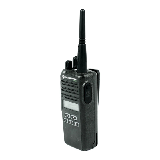
RADIO OVERVIEW 1 Channel Selector Knob Accessory Connector 2 On/Off and Volume Knob 10 Programming Port 3 LED Indicator CP185 4 Speaker 5 Microphone 6 Liquid Crystal Display (LCD) 11 Front Left/Right Buttons 12 Front Programmable Buttons 7 Push-to-Talk (PTT) Button 8 Side Programmable Buttons English English... -
Page 8: Led Indicator
1. Channel Selector Knob 7. Push-to-Talk (PTT) Button Used to select channels in normal radio operation mode. Press and speak to microphone to send message. Release and listen to receive messages. 2. On/Off and Volume Knob Note: If a channel is programmed with the Busy Channel Turn the ON/OFF/Volume Control knob clockwise to turn Lockout feature, you can only transmit on that the radio ON. -
Page 9: Led Colors
LED COLORS LED Color State Indication Green Illuminated Radio is transmitting in normal mode. Radio is transmitting in scrambling mode. Normal Blinking Radio is receiving in normal mode. Channel is busy. Radio passed self test during powering up. Amber Illuminated Monitor activated. -
Page 10: Lcd Display And Icons
LCD Display and Icons Description Function Indicator Displays selected channel, programming parameters, status messages and any error or information messages. Programming Illuminates when radio is in Mode Indicator Programming Mode. Description Function Indicator Keypad Lock Illuminates when keypad is Indicator locked. -
Page 11: Programmable Buttons
Programmable Buttons Button Function The programmable buttons consist of: Keypad Lock Locks or unlocks all buttons except PTT, Side Programmable Button 1, Side Programmable Button 2, Channel Selector Knob and ON/OFF/ • Side Programmable Button 1 Volume Knob. Monitor Monitors the channel for any activity as long as the button is pressed. - Page 12 The default functions assigned to your radio are described in Button Function the table below Scrambling Enables or disables scrambling feature for the Enable/Disable selected channel. Press Side Side Front Front Front Volume Set A programmable button used to control the Type Button 1 Button 2...
-
Page 13: Getting Started
GETTING STARTED To Attach Antenna Fasten the antenna to the radio by placing the Attaching and Removing the Antenna threaded end of the antenna into the Antenna Connector. Rotate the antenna clockwise until tight. To Remove Antenna Threaded End Turn the antenna in a counter-clockwise direction of Antenna until it disengages from the radio. -
Page 14: Attaching And Removing The Battery
Attaching and Removing the Battery To Attach Battery Fit the battery slots with the grooves on the radio. Grooves Slide the battery upwards until a click is heard. To Remove Battery Slide the battery latch away from the radio. Slide the battery downwards. Pull the battery away from the radio. -
Page 15: Attaching And Removing The Belt Clip
Attaching and Removing the Belt Clip To Attach Belt Clip Align mounting rails of the belt clip with the grooves Release Tab of the radio. Slide the belt clip downwards until it clicks into place. Mounting Grooves To Remove Belt Clip Safely insert a flat tool between the release tab and the back surface of the radio. -
Page 16: Charging The Battery
Charging the Battery Turn the radio OFF before charging the battery. Insert a battery, or a radio with a battery into the charger’s pocket by: a) Aligning the groove on each side of the battery with the corresponding raised rail on each side of the charger pocket OR b) Pressing the battery towards the rear of the pocket OR... - Page 17 LED Color Charging Status Solid Red Charging Blinking Red Battery Fault Solid Green Charge Complete Blinking Green Trickle Charging Single Green Blink Power On Blinking Yellow Waiting to Charge Note: To get maximum use from a new battery, charge it overnight (12 to 16 hours) before using the battery for the first time.
-
Page 18: Scan
SCAN If your radio has switched to a non-priority channel during priority scan, it still checks for activity on the priority channel. If activity is detected there, the radio switches to the priority Scan allows you to monitor multiple channels and receive calls channel. -
Page 19: Voice Operated Transmit (Vox)
VOICE OPERATED TRANSMIT (VOX) When the VOX headset/microphone is connected, your radio may be used in hands-free operation. To start the VOX feature: Connect the VOX headset to the accessory connector of the radio. Make sure the radio is turned OFF before connecting the VOX accessory. -
Page 20: Voice Inversion Scrambling
VOICE INVERSION SCRAMBLING Your radio has the Voice Inversion Scrambling feature which gives you an extra layer of privacy. This scrambling function is implemented via a frequency inversion in analog mode using two standard codes (3.29 KHz and 3.39 KHz). To Enable and Disable the Scrambling Mode Configure one of the programmable buttons for Scrambling Mode. -
Page 21: Front Panel Programming Mode
FRONT PANEL PROGRAMMING Assessing Front Panel Programming Mode MODE Parameters Press the to scroll through the parameters This mode allows you to change the feature parameters to for each menu or sub-menu item, or enhance the use of your radio. Note: This feature is only supported by certain models. - Page 22 1st Level 2nd Level Main Menu Setting Remarks Sub-Menu Sub-Menu BCKLIGHT AUTO Selecting AUTO causes the backlight to automatically (Backlight) TOGGLE extinguish, if there is no keypress for more than 5 seconds. Pressing the Backlight button again prolongs illumination time. Selecting TOGGLE allows the Backlight button toggle to control the ON/OFF status of the backlight.
-
Page 23: Main Menu
1st Level 2nd Level Main Menu Setting Remarks Sub-Menu Sub-Menu ACCESORY SPK GAIN Allows you to adjust the external (Accessory) (External Speaker speaker loudness when accessories Gain) are connected to radio. +2 will set the external speaker gain to maximum level and -2 will set the external speaker gain to minimum level. - Page 24 Main 1st Level 2nd Level Settings Remarks Menu Sub-Menu Sub-Menu CHANNEL RX PL CH-001 CSQ (Carrier This is the TPL or DPL code that the channel will use to (Receive TPL/ … Squelch) unsquelch the received signal. CSQ indicates that radio operates DPL) CH-099 TPL 067.0…...
- Page 25 Main 1st Level 2nd Level Settings Remarks Menu Sub-Menu Sub-Menu CHANNEL PRIME CH (Prime The channel that you wish to spend most of your time monitoring. The (Cont’d) Channel) 001... radio will always switch back to the Prime Channel if it is idle for more than the preprogrammed hang-time in other channels.
- Page 26 Notes: English...
-
Page 27: Tpl And Dpl Frequencies And Codes
TPL AND DPL FREQUENCIES AND Table 1: TPL Frequency CODES Equivalent PL TPL Freq (Hz) Motorola Code Code The following information in the tables are to guide the user to 97.4 select the appropriate TPL (Tone Private Line) or DPL (Digital Private Line) codes so that they can expand usage of the 100.0... - Page 28 Table 1: TPL Frequency Equivalent PL TPL Freq (Hz) Motorola Code Code 186.2 192.8 203.5 206.5 210.7 218.1 225.7 229.1 233.6* 241.8 250.3 254.1* TPL1* – TPL1 – TPL2* TPL2 – TPL 3* TPL3 Note: The TPL Frequencies marked with an asterisk (*) are not part of the 39 standard EIA/TIA-603 CTCSS Code Frequency.
-
Page 29: Dpl Codes
DPL Codes Table 2: DPL Codes DPL Code Motorola Code Table 2: DPL Codes DPL Code Motorola Code English... - Page 30 Table 2: DPL Codes Table 2: DPL Codes DPL Code Motorola Code DPL Code Motorola Code 525(*) English...
- Page 31 Table 2: DPL Codes DPL Code Motorola Code 645(*) Note: The codes marked with an asterisk (*) are not part of the 83 standard EIA/TIA-603 codes. English...
-
Page 32: States And Canada
(90) days This limited warranty is a consumer's exclusive Accessories that are from the date returned to the remedy, and applies as follows to new Motorola Repaired or Replaced. consumer, whichever is longer. Products, Accessories and Software purchased by consumers in the United States, which are accompanied by this written warranty. - Page 33 Abuse & Misuse. Defects or damage that result from: any way by someone other than Motorola, or its (a) improper operation, storage, misuse or abuse, authorized service centers, are excluded from accident or neglect, such as physical damage (cracks, coverage.
- Page 34 This warranty extends only to the first consumer (e.g. CD-ROM, or purchaser, and is not transferable. floppy disk). HOW TO OBTAIN WARRANTY SERVICE OR OTHER INFORMATION? Contact your Motorola point of purchase. English...
- Page 35 SOFTWARE COPYRIGHT NOTICE PATENT NOTICE The Motorola products described in this manual may This product is covered by one or more of the following include copyrighted Motorola and third party software United States patents. stored in semiconductor memories or other media.
- Page 36 Notes: English...
-
Page 37: Accessories
ACCESSORIES BATTERIES Motorola Part The following accessories parts are compatible with model Description Number number CP185. PMNN4080_ Li-Ion High Capacity – 2150mAh: 14hrs talktime @ 5-5-90 at High Power ANTENNAS PMNN4081_ Li-Ion – 1500mAh: 10hrs talktime @ Motorola Part 5-5-90 at High Power... - Page 38 AUDIO ACCESSORIES CHARGERS AND POWER ADAPTERS Motorola Part Motorola Part Description Description Number Number ™ MAG ONE Branded PMLN5228_ Tri-Chem Single Unit Charger Base PMLN4442_ Earbud with In-Line Microphone / PTT / VOX Switch (MagOne) PMLN5398_ Single Unit Charger Base with US 2-Pin...
- Page 39 Note: Certain accessories may be or may not be available at the PMMN4029_ Remote Speaker Microphone with IP57 time of purchase. For latest information on accessories, Rating contact your Motorola point of purchase or visit: RLN6230_ High Noise Kit, Black (Includes Foam http://www.motorola.com/governmentandenterprise. Earplugs with Acoustic Tube)
- Page 40 Notes: English...
- Page 42 MOTOROLA and the Stylized M Logo are registered in the US Patent & Trademark Office. All other product or service names are the property of their respective owners. © 2008 by Motorola, Inc. All rights reserved. *6878080A01* 6878080A01-A...