Table of Contents
Table of Contents
Troubleshooting

Related Manuals for GE Mentor Visual iQ


Summary of Contents for GE Mentor Visual iQ
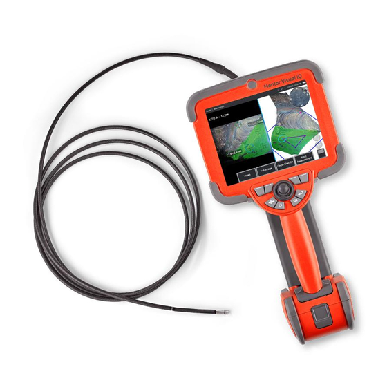
- Page 1 Mentor Visual iQ VideoProbe User’s Manual MVIQAMANUAL Rev. B 07/30/2014...
- Page 2 07/30/2014...
-
Page 3: Table Of Contents
Table of Contents Introduction Working with Video About this Manual Recording Live Video Getting Help Working with a Recalled Video System Overview Measuring Features and Indications Safety Information 3D Phase Measurements (3DPM) Informations sur la sécurité Stereo Measurements Start Up Comparison Measurements Component Identification Troubleshooting Measurements... -
Page 4: Introduction
To ensure operator safety, please read and understand this manual prior to using the system. Getting Help For additional assistance, go to www.ge-mcs.com for a complete listing of contact information. Technical Support contact information follows: Global Phone: 1-866-243-2638 Email: [email protected] Website: http://www.geittechsupport.com... - Page 5 Standard Equipment Visual iQ 2-hour Li-Ion Battery Visual iQ Storage Case AC Adapter/Battery Charger Optical Tip Storage Case USB Thumbdrive Containing Documentation, including User's Manual Safety and Essential Use Hard Copy Quickstart Card Optional Accessories Display Port Video Cable Insertion Tube Gripper Insertion Tube Rigidizer Handset Holder Headset (wired or wireless)
-
Page 6: Safety Information
Safety Information Note: Before using or servicing the system, read and understand the following safety information. Symbols and Terms The following symbols appear on the product: See accompanying documentation. General Warnings The following warning statements apply to use of the system in general. Warning statements that apply specifically to particular procedures appear in the corresponding sections of the manual. - Page 7 Battery Warnings Only use the battery and power supply specified for use with the system. Before use, thoroughly review the instructions in this manual for the battery and battery charger to fully understand the information contained in them, and observe the instructions during use. WARNING •...
-
Page 8: Informations Sur La Sécurité
Informations sur la sécurité Remarque: avant l’utilisation ou l’entretien du système, vous devez lire et comprendre les informations de sécurité qui suivent. Symboles et termes employés Les symboles suivants sont apposés sur le produit: Voir la documentation jointe. Avertissements généraux Les avertissements suivants s’appliquent à... - Page 9 Avertissements liés à la batterie Utilisez uniquement la batterie et l’alimentation spécifi ées pour être utilisées avec le système Visual iQ. Avant utilisation, lisez attentivement les instructions contenues dans ce manuel relatives à la batterie et au chargeur de batterie pour bien les comprendre, et respectez ces instructions pendant l’utilisation de l’appareil. AVERTISSEMENT •...
-
Page 10: Start Up
Start Up Component Identification – LCD Touchscreen – DisplayPort Output (2.1), USB 3.0 Client Micro B Port (2.2), Two USB 3.0 Host Type A Ports (2.3), 3.5 mm Headset/Microphone Jack (2.4). – Two-hour Lithium Ion Battery – Battery Release Button – Battery Charge Indicator –... -
Page 11: Touchscreen And Keys - Dual Control Systems
– Touch the lower left corner of the display screen (typically contains the GE Logo) or the touch screen). Use the joystick to change the zoom magnification bar (this and other short-press the Menu key to open the Global Menu. -
Page 12: Unpacking, Assembling, And Powering The Visual Iq
Unpacking, Assembling, and Powering the Visual iQ Unpacking and Putting Away the System (Small Case) Caution: If you do not pack the system carefully, as described here, damage might occur. – The insertion tube (shown in red for clarity) is held in the case’s internal storage reel, which is accessed through the orange funnel shown here. -
Page 13: Unpacking And Putting Away The System (Large Case)
Unpacking and Putting Away the System (Large Case) Caution: If you do not pack the system carefully, as described here, damage might occur. – Remove tray to access additional storage space. – The insertion tube (shown in red for clarity) is held in the case’s internal storage reel, which is accessed through the orange funnel shown here. Install the insertion tube before installing the probe-and-handset assembly and remove it after removing the probe-and-handset assembly. -
Page 14: About The Battery
About the Battery The Visual iQ is powered by a 10.8 V (nominal), 73 Wh, 6.8 Ah Lithium Ion battery. Installing the Battery Insert the battery into the handset. The battery is installed properly when the latching mechanism is engaged. Caution—Do not force the battery ( ) into the handset ( ), as damage may occur. -
Page 15: Supplying Power To The Visual Iq
System Power Off Touch the lower left corner of the display screen (which typically contains the on-screen GE Logo ( ) or the hard key at any time to open or close the Global Menu, which provides access to several features including Shut Down ( ). -
Page 16: Changing Probes And Optical Tips
Changing Probes and Optical Tips Attaching and Removing the Probe To attach the probe to the handset: – Insert the pin at the base of the handset into the mating groove at the bottom of the probe. – Rotate the probe towards the back of the handset, applying enough pressure for the latching mechanism to “click.”... -
Page 17: Setting Up The Visual Iq Operating System
– Allows the user to set their preferred measurement units (inches vs. mm), manage and verify measurement tips, and import and export preset annotations. – Generates a Troubleshooting Log to be emailed to and evaluated by GE Technical Support. If log generation is required, GE Technical Support will guide the user through the process. -
Page 18: Working With Profiles
Working with Profiles A Profile defines several parameter settings. As long as more than one profile is available, (the Visual iQ is delivered with only a Default Profile), the operator is asked to select a Profile every time the system is powered on. Follow these instructions to create a new profile or select an existing one. -
Page 19: System Setup
System Setup – Tap the on-screen GE Logo (or press the hard key) to open the Global Menu, then open the Setup Menu. – Select to alter the system-specific settings shown here. – Drag your finger up or down the screen. This bar will move to show the current position among the list of system-specific settings. - Page 20 Steering Sensitivity Settings – Turing Daylight Saving Time to ON causes the system to automatically adjust the time setting. – The user can select from two probe steering modes: Steer or Steer and Stay™. – Specify 12 or 24 hour Time Format. In either mode, the bending neck articulates to follow the joystick motion.
-
Page 21: Screen & Display Setup
Screen & Display Setup – Tap the on-screen GE Logo (or press the hard key) to open the Global Menu, then open the Setup Menu. – Select to alter the display-screen appearance and operation. – Turn the display screen’s touch-sensitive control ON or OFF. Once turned OFF, the icon shown here appears at the top of the display screen. -
Page 22: Connectivity Setup (Wifi, Bluetooth, Pcs, And Networks)
Connectivity Setup – Tap the on-screen GE Logo (or press the hard key) to open the Global Menu, then open the Setup Menu. – Select to work with settings that control the connection of the Visual iQ to WiFi networks and Bluetooth devices. - Page 23 Mapping the Network Drive and Sharing Folders – If you choose to give the Visual iQ’s File Manager access to a folder on a network- connected computer, click on Setup (see above) to open the network-mapping process shown here. Next, select Done to confirm that the network connected PC has at least one folder identified for sharing.
-
Page 24: Image & Video Setup
Visual iQ or paired via Bluetooth). – Should a not-yet-defined tip configuration require an alternative Distortion Correction Table, Contact GE Technical Support. A table supplied by GE Technical Support will include instructions on how to Import the file. -
Page 25: Measurement & Annotation Setup
Measurement & Annotation Setup – Tap the lower-left corner of the display (typically contains a GE Logo) or (or press hard key) at any time to open the Global Menu, which provides access to the Setup Menu. – Select to alter the Measurement and Annotation-specific settings shown here. -
Page 26: Capturing And Adjusting Images
– Straightening the Bending Neck: Long press this button to HOME or straighten the bending neck for safe withdrawal and storage of the insertion tube. – Setting the Steering Mode: Short press this button to choose between Steer or Steer and Stay mode. In either mode, the bending neck articulates to follow the joystick motion. -
Page 27: Freezing The Image
Freezing the Image Freeze an image to temporarily capture it for review or adjustment. Moving the joystick in a frozen view does not articulate the probe tip. – Briefly press either of these keys or tap anywhere on a live on-screen image to freeze the display. -
Page 28: Selecting A View
Selecting a View When a 2D image is frozen (or a 3DPM image is recalled), the user can select from various Views as described below. – Anytime an image is frozen, select to choose from all available View options. – Displays a normal dynamic range image created by applying Adaptive Noise Reduction (ANR) processing to live video frames prior to the freeze request. -
Page 29: Saving Image Files
– At all times, the intended saving location (in this case the Dev directory located on the D drive) is listed here. After a file is stored, the status bar at the top of the screen indicates “Saved.” The file name (described below) and format are also listed. –... -
Page 30: Working With A Recalled Image
Follow these steps to locate and Recall a stored file: – Recall a stored image or video by tapping the on-screen GE Logo (or press the hard key) to open the Global Menu, then select File Manager. -
Page 31: Zoom To Magnify
Zoom to Magnify The Zoom feature magnifies the view of live, frozen, and recalled images. Because the zooming process is digital, pixilation increases as the image is magnified. Note: The Visual iQ offers two equivalent zooming methods. – Select this soft key to launch the Zoom control bar. –... -
Page 32: Image Transformation Settings
Image Transformation Settings These settings, accessed by selecting the Image Menu, alter the appearance of live images. (Some of these settings also affect frozen or recalled images.) At any time, the values assigned to these eight transformation settings can be saved as a user-named Preset. - Page 33 – Tap to turn Adaptive Noise Reduction (ANR) ON or OFF. ANR works to reduce the – Tap to turn the Single View feature ON or OFF. Single View is useful while positioning amount of noise (which appears as a grainy image) visible when the probe is positioned a stereo optical tip.
-
Page 34: Working With Preset Image Transformation Settings
Working with Preset Image Transformation Settings Values assigned to the image transformation settings can be saved as a user-named Preset. When recalled, all transformation settings will revert to the values assigned when the Preset was created. Each user-named Preset appears as a soft key in the Image Menu. -
Page 35: Working With A Split Screen
Working with a Split Screen A split screen displays two images side-by-side in any combination of live, frozen, or recalled. Since half-screen still images are cropped, dragging a finger across the display or moving the joystick allows you to pan side-to-side within the image. –... -
Page 36: Annotating With Text And Arrows
Annotating with Text and Arrows Annotating an image means adding text or arrows to point out areas of interest: cracks, indications, etc. You can annotate live, frozen, and recalled images. – Select to launch the Annotation feature. – Tap to switch between the Soft Key Bar’s top and bottom row. Double tapping in this location hides or displays the soft keys and status bar. -
Page 37: Adding Audio Notes To An Image
Adding Audio Notes to an Image During the process of saving an image, audio notes can be added provided a microphone is first attached to the Visual iQ. – Long press the Save hard key to begin the image saving process. –... -
Page 38: Working With Video
Recording Live Video – Tap the lower-left corner of the display (typically contains a GE Logo) at any time to open the Global Menu, which provides access to the video Record button. – Select to begin recording video in the user-selected format (click here to learn about configuring Video Settings). -
Page 39: Measuring Features And Indications
-Measurement results are valid only when taken in air. To measure through liquid, contact GE Inspection Technologies. -GE Inspection Technologies cannot guarantee the accuracy of measurements calculated by the Visual iQ system. Accuracy varies with the operator’s ability. -The Visual iQ system can display measurement images that were captured on the Everest XLG3™ and XLGo VideoProbe systems, including their previously captured measurements. - Page 40 Measurement Types Measurement Tips The Visual iQ system supports three types of measurement: 3D Phase, stereo, Note: 3DPM tips are automatically identified by the system. Stereo tips must be and comparison. manually selected each time a stereo measurement is performed. Unlike standard optical tips, 3D PhaseProbe®...
-
Page 41: Phase Measurements (3Dpm)
3D Phase Measurements (3DPM) 3D Phase Measurement optical tips and probe capture a three-dimensional surface scan of the object. Measurements are then made directly on the surface and displayed on the image. Preliminary steps of matching cursors or marking shadow lines are not necessary. - Page 42 Capturing 3DPM Images – When the target is in position, select this soft key (or long hold The 3D Phase Measurement scan will begin. Note: Hold the probe still for approximately one second during the surface scan. Multiple images are taken to complete the scan, and the probe must be held still during this sequence.
- Page 43 Making 3DPM Measurements (Depth Profile Example) Note: While the following procedure applies specifically to a Depth Profile measurement, refer to this procedure and the information in the section titled Types of Phase Measurement to conduct any type of 3DPM. – To create a Depth Profile measurement, place the first and second cursors on a flat surface on opposite sides of the area of interest.
- Page 44 Types of 3D Phase Measurements This section specifically addresses cursor placement for each type of 3D Phase Measurement. Description: Description: Description: Description: Description: Description: Linear (Point- The perpen- The perpen- The length of a A profile of the The surface area to-Point) dicular distance dicular distance...
- Page 45 Point Cloud View (3DPM) The point cloud view offers the following advantages: • Provides a rough idea of feature size. • Shows location of high and low points to help profile and depth measurement cursor positioning. • Shows the level of noise relative to indication size. You can then move the probe closer if indication is hidden in surface noise bumps.
-
Page 46: Stereo Measurements
Stereo Measurements Stereo measurements require the use of StereoProbe measurement tips to capture stereoscopic images of a target — two pictures of the same target from two different angles. To measure the target, the Visual iQ uses triangulation based on these two side-by-side images. - Page 47 About the Matching Cursors For each cursor you place on the left image during stereo measurement, the system places a matching cursor on the right image for use in triangulation. You must place each left cursor on an image point (a pixel) that has sufficient surrounding detail to differentiate it from its neighboring pixels.
- Page 48 Stereo Mode Measurement Procedure, Part 1 Prior to collecting stereo measurements, a calibrated stereo optical tip must be attached to your Visual iQ. Properly position the tip for measurement (click here to see how to position the tip), which may be aided by temporarily displaying a single image by turning Single View mode ON (click here to select Single View and learn about other Image Transformation settings).
- Page 49 Stereo Mode Measurement Procedure, Part 2 – Tap the screen (or hit ) to display the second cursor. Position it as described in items 5 and 6. Note: Generally, you get the best results by leaving the matching cursors exactly where the system places them. However, under certain circumstances, such as when a repeating pattern exists, you may need to help the system find the correct match.
- Page 50 Features of the Stereo Measurement Screen – The currently active cursor appears larger than all others. Note that this cursor’s position can be altered by the joystick or by dragging it across the screen. – Tap any on-screen dimension to select it for repositioning (by dragging or with joystick) –...
- Page 51 Stereo Measurement Types This section specifically addresses cursor placement for each type of stereo measurement. Description: Description: Description: Description: Description: Linear (Point-to- The perpendicular The perpendicular The surface The length of a Point) distance from a distance between a area contained nonlinear feature point to a line surface and a point...
-
Page 52: Comparison Measurements
Comparison Measurements Comparison measurements rely on the known dimensions of an object that has been set in the field of view either by the manufacturer or by the probe or takes advantage of known dimensions within the frozen image. The Visual iQ processor uses these known dimensions as a reference scale for measuring an unknown target. -
Page 53: Troubleshooting Measurements
Troubleshooting Measurements Inaccurate 3D Phase or Stereo Measurements • Move the probe tip as close as possible to the target, maximizing magnification. • After capturing an image, verify that the tip attached to the probe matches the tip that is selected in the software. Click here to learn more about managing probe tips. -
Page 54: Managing Files
Ejected using the features described here. – Insert the USB Storage Device into either of these ports. –To access files or folders on the USB drive, tap the on-screen GE Logo (or press the hard key) to open the Global Menu, then select File Manager. -
Page 55: Editing Files And Folders/Creating Folders
Copied, Cut, Pasted, Deleted, Renamed, or Created (in the case of folders). Follow these steps to Edit files or folders: – To edit files or folders, tap the on-screen GE Logo (or press the hard key) to open the Global Menu, then select File Manager. Alternatively, select the Recall soft key (when enabled), which allows you to recall a stored image or video and/or edit files and folders. -
Page 56: Mdi
Loading and Unloading Menu Directed Inspections Follow this process to load or unload a Menu Directed Inspection. Note: MDI inspection files have the file extension of .mdz. A maximum of fifty MDI inspection files may be loaded at any given time. –... -
Page 57: Starting A Menu Directed Inspection
Starting a Menu Directed Inspection – Select to begin the MDI process. – Select any loaded inspection. – Select to browse for and Resume a previously active inspection. – Resume the Last active inspection. – Indicates a newly loaded inspection. –... -
Page 58: Selecting An Inspection Point
Selecting an Inspection Point At this time, you can navigate through the inspection levels until you have reached the desired inspection point. – Inspection name and equipment serial number. – Select to navigate to the inspection’s next-lowest organization level. – Navigating to the bottom level of the inspection allows you to record images and videos. -
Page 59: Saving An Image Or Video In An Mdi Inspection
Saving an Image or Video in an MDI Inspection To save an image in the selected inspection point, press the SAVE hard key. During the save process, some of the following are available: Required Characterization - If required, a characterization list appears before the save menu. -
Page 60: Viewing Reference Material
Viewing Reference Material – Select at any level within the inspection to access Reference Material associated with the level or point – Select any PDF, image, or video material to open and view on the Visual iQ display – Select Show All to access all Reference Material associated with the active inspection, which may be more than the material associated with the active level. -
Page 61: Generating An Mdi Report
Generating an MDI Report Follow this process to generate an MDI report. – Select to Generate a Report and, if no inspection is active, choose the desired inspection. – After selecting the inspection for which you wish to generate a report, choose Done. –... -
Page 62: Customizing An Mdi Report
Customizing an MDI Report Customize an inspection report by specifying the following parameters: REPORT OPTIONS: • Report Name – Override the automatic inspection report file name. • Report Format – Choose the version of MS Word in which to publish. •... -
Page 63: Maintenance And Troubleshooting
– Clean the probe tip, including the lens on the camera head. Use glass cleaner or If you discover conditions that require evaluation or repair, return the system to GE 70% alcohol-to-water solution and a pointed cotton swab. - Page 64 Inspecting and Cleaning the Handset – Disconnect the power cord from the power source. – Check for damage or contamination, including any bent pins on the electrical connector. – Use a soft cloth dampened with glass cleaner or 70% alcohol-to-water solution to clean all parts of the handset, except the electrical connector. Use great care when cleaning the electrical contact pins of the connector.
-
Page 65: Troubleshooting Guide
Image quality is otherwise Various • If available connect a different probe to handset. poor. • If image quality issue is associated with a specific probe contact GE Inspection Technologies to obtain a return material authorization (RMA). No image appears in the Various •... - Page 66 • Insertion tube is stuck. • Gently push the insertion tube in and out with a slight twisting motion in order to free the probe. If probe cannot be freed freely withdraw from the contact GE Inspection Technologies Tech Support. storage reel. Handset...
- Page 67 • Contact GE Inspection Technologies for a replacement charger. • Defective Battery • Try another battery. • If replacement battery does not restore operation contact GE Inspection Technologies to obtain a return material authorization (RMA). System runs when connected to AC •...
-
Page 68: Appendices
APPENDICES Appendix A. Technical Specifications Operating Temperature -25ºC to 100ºC (-13ºF to 212ºF). Reduced articulation below 0ºC (32ºF) System -20º to 46ºC (-4ºF to 115ºF). LCD may require warm-up period below 0ºC (32ºF). Storage Temperature -25º to 60ºC (-13ºF to 140ºF) Relative Humidity 95% max, non-condensing Waterproof... - Page 69 IP55 (Disassembled), IP67 (Assembled) Patent Information Mentor Visual iQ is covered under one or more of the following US Patents: US5734418, US5754313, US6468201, US7819798, US8310533, US8368749, US7262797, US7782453, US8514278, US8213676, US7821649, US8107083, US8422030, US7969583, US8253782, US7902990, US8310604, US8165351, US8760447, US8411083.
- Page 70 Audio Data PC compatible AAC (.m4a) file format Image Control Invert, Inverse+, Adaptive Noise Reduction, Distortion Correction, Illumination, Brightness, Long Exposure, Single View, Zoom (5x digital), Image Capture and Recall Digital Zoom Continuous (5x) Image Formats Bitmap (.BMP), JPEG (.JPG) Video Format MPEG4 AVC /H.264 (.MP4) Text Annotation...
-
Page 71: Appendix B. Optical Tip Table
Appendix B. Optical Tip Table Mentor Visual iQ 6.1mm tips Part No. Color FOV (deg) DOF mm (in) Forward View T6150FF None 50-inf (2.36-inf) XLG3T6150FG White 12-200 (.47-7.87) XLG3T61120FG Black 5-120 (.20-4.72) XLG3T6180FN Orange 3-20 (.12-.79) XLG3T6190FF Yellow 20-inf (.79-inf) -
Page 72: Appendix C. Chemical Compatibility
GE Inspection Technologies warrants its VideoProbe components, when new, to be free from defects in material and workmanship and to perform in accordance with manufacturer’s specifications under normal use and service for a period of one year from the date of purchase from GE Inspection Technologies or its authorized distributors, except that, the light source is warranted for a period of 3 years from the date of purchase, the battery is warranted for a period of 30 days from the date of purchase, and where used, servo motors in the articulation drive system are warranted for the life of this VideoProbe product. -
Page 73: Appendix E. Verifying Measurement Tips
Appendix E. Verifying Measurement Tips Verify measurement tips each time you use them to ensure that no mechanical damage has degraded their accuracy. Visual iQ systems are shipped with a measurement verification block. This tool lets you verify the accuracy of measurement tips. -
Page 74: Appendix F. Environmental Compliance
Mercury creates hazardous vapors at room temperature. Exposure to high concentrations of mercury vapor can cause a variety of severe symptoms. Risks include chronic inflammation of mouth and gums, personality change, nervousness, fever, and rashes. Visit www.ge-mcs.com for take-back instructions and more information about this initiative. 07/30/2014... -
Page 75: Appendix G. Regulatory Compliance
2004/108/EC Electromagnetic Compatibility Directive. The Visual iQ system is in conformance with the following standard: EN61326-1. Declarations of Conformity are held by GE Inspection Technologies GmbH: GE Inspection Technologies GmbH Product Service Center Lotzenäcker 4... - Page 76 FCC Compliance Statement: This device complies with part 15 of the FCC Rules. Operation is subject to the following two conditions: 1) This device may not cause harmful interference and 2) This device must accept any interference received, including interference that may cause undesired operation. Note: This equipment has been tested and found to comply with the limits for a Class B digital device, pursuant to part 15 of the FCC Rules.
- Page 77 Complies with the Canadian ICES-003 Class B specifications. Cet appareil numérique de la classe B est conforme à la norme NMB-003 du Canada. IMPORTANT NOTE: IC Radiation Exposure Statement: This equipment complies with IC radiation exposure limits set forth for an uncontrolled environment. The transmitter module may not be co-located with any other transmitter or antenna.
- Page 78 Brazil Wireless Statement: Este equipamento opera em caráter secundário, isto é, não tem direito a proteção contra interferência prejudicial, mesmo de estações do mesmo tipo, e não pode causar interferência a sistemas operando em caráter primário. (This equipment operates on a secondary basis, ie, not entitled to protection against harmful interference, even of the same type stations, and cannot cause interference to systems operating on a primary basis.) South Korea Wireless Statement: (EMC registration is done on this equipment for a business use only (Class A).
-
Page 79: Appendix H. Creating A Personalized Logo File
A custom logo can be loaded into the display, where it will appear in the lower left image into a transparency. corner (in place of the default GE logo). Suitable logos must be saved as PNG file format and must be no larger than 140 by 140 pixels. It is advisable to use image files that are approximatley square. -
Page 80: Appendix I. Open Source Software Availability
554-2000, option 3. Appendix J. Restoring Factory Settings – Tap the on-screen GE Icon at any time to open or close the Global Menu, which provides access to several features including the Setup Menu. – Tap to open the Setup Menu. -
Page 81: Index
AC-to-DC power adaptor 15 FOV 52 Adaptive Noise Reduction (ANR) 33 Freeze 27 Add Audio 37 Annotation 36 ANR 33 GE Logo 15 Arrows 36 Global Menu 17 Audio Notes 37 Image 32 Battery Warnings 7 image file type 24... - Page 82 Measuring 39 Sound Recording 21 Menu Directed Inspections 56 Speaker 24 Microphone 24 Specifications 61 MTD Number 41 Steer 20 Steer and Stay 20 Steer and Stay mode 26 Open Source Software 72 Steering Mode 26 Operating Language 10, 20 Steering Sensitivity Settings 20 Stereo Index 25, 46 Optical Tips 16...
- Page 83 2 Tai Yip Street Kwun tong, Kowloon Hong Kong Tel: +852 2877 0801 E-mail: [email protected] www.ge-mcs.com Assembled in USA by GE Inspection Technologies ©2014 General Electric Company. All rights reserved. Specifications subject to change without notice. ©2014 VideoLAN Printed in USA 07/30/2014...