Yamaha R-S300 Service Manual
Hide thumbs
Also See for R-S300:
- Owner's manual (322 pages) ,
- Manuel d'utilisation (8 pages) ,
- Owner's manual (78 pages)
Table of Contents
This manual has been provided for the use of authorized YAMAHA Retailers and their service personnel.
It has been assumed that basic service procedures inherent to the industry, and more specifi cally YAMAHA Products, are already known
and understood by the users, and have therefore not been restated.
WARNING:
IMPORTANT:
The data provided is believed to be accurate and applicable to the unit(s) indicated on the cover. The research, engineering, and service
departments of YAMAHA are continually striving to improve YAMAHA products. Modifications are, therefore, inevitable and
specifi cations are subject to change without notice or obligation to retrofi t. Should any discrepancy appear to exist, please contact the
distributor's Service Division.
WARNING:
IMPORTANT:
■ CONTENTS
To Service Personnel ............................................2
Impedance Selector ...............................................3
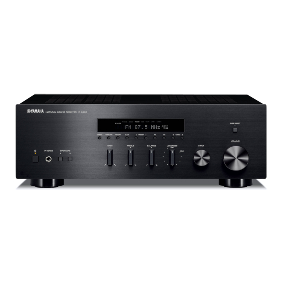
Front Panels .............................................................4
Rear Panels ...........................................................5–6
Remote Control Panel ..........................................7
Specifications .......................................................8–9
Internal View .......................................................... 10
Service Precautions ............................................ 10
Disassembly Procedures ............................. 11–13
Updating Firmware .......................................... 14–17
Self-Diagnostic Function ............................ 18–29
R-S300
SERVICE MANUAL
IMPORTANT NOTICE
Failure to follow appropriate service and safety procedures when servicing this product may result in personal injury,
destruction of expensive components, and failure of the product to perform as specifi ed. For these reasons, we advise
all YAMAHA product owners that any service required should be performed by an authorized YAMAHA Retailer or
the appointed service representative.
The presentation or sale of this manual to any individual or fi rm does not constitute authorization, certifi cation or
recognition of any applicable technical capabilities, or establish a principle-agent relationship of any form.
Static discharges can destroy expensive components. Discharge any static electricity your body may have
accumulated by grounding yourself to the ground buss in the unit (heavy gauge black wires connect to this buss).
Turn the unit OFF during disassembly and part replacement. Recheck all work before you apply power to the unit.
Amp Adjustment ...............................................30–31
Display Data .......................................................32–33
Ic Data ...................................................................34–36
Block Diagram ........................................................37
Printed Circuit Boards .................................38–53
Pin Connection Diagrams ...................................54
Schematic Diagrams .......................................55–60
Replacement Parts List ................................61–71
Remote Control .....................................................72
Advanced Setup ................................................ 73–74
RECEIVER
Table of Contents

Related Manuals for Yamaha R-S300


Summary of Contents for Yamaha R-S300
- Page 1 This manual has been provided for the use of authorized YAMAHA Retailers and their service personnel. It has been assumed that basic service procedures inherent to the industry, and more specifi cally YAMAHA Products, are already known and understood by the users, and have therefore not been restated.
-
Page 2: To Service Personnel
R-S300 ■ TO SERVICE PERSONNEL AC LEAKAGE 1. Critical Components Information WALL EQUIPMENT TESTER OR OUTLET UNDER TEST EQUIVALENT Components having special characteristics are marked must be replaced with parts having specifications equal to those originally installed. 2. Leakage Current Measurement (For 120V Models Only) - Page 3 R-S300 ■ IMPEDANCE SELECTOR WARNING: Do not change the setting of the IMPEDANCE SELECTOR switch when the unit power is switched on, as doing so may damage the unit. IMPEDANCE SELECTOR...
-
Page 4: Front Panels
R-S300 ■ FRONT PANELS R-S300 (U, C, R, A, L models) R-S300 (G model) -
Page 5: Rear Panels
R-S300 ■ REAR PANELS R-S300 (U, C models) R-S300 (R model) R-S300 (A model) - Page 6 R-S300 R-S300 (G model) R-S300 (L model)
- Page 7 R-S300 ■ REMOTE CONTROL PANEL RAX23...
-
Page 8: Specifications
R-S300 ■ SPECIFICATIONS ■ Audio Section ■ FM Section Minimum RMS Output Power (Power Amp. Section) Tuning Range (20 Hz to 20 kHz) U, C models ............87.5 to 107.9 MHz (8 ohms, 0.04 % THD) ........50 W + 50 W R, A, G, L models .......... - Page 9 Apple Inc., registered in the U.S. and other countries. Bluetooth is a registered trademark of the Bluetooth SIG and is used by Yamaha in accordance with a license agreement. • DIMENSIONS Top view ø...
-
Page 10: Internal View
R-S300 ■ INTERNAL VIEW Top view OPERATION (12) P.C.B. OPERATION (13) P.C.B. OPERATION (14) P.C.B. (R model) MAIN (3) P.C.B. AM/FM TUNER DOCK P.C.B. FUNCTION (2) P.C.B. FUNCTION (3) P.C.B. FUNCTION (1) P.C.B. MAIN (2) P.C.B. MAIN (1) P.C.B. POWER TRANSFORMER OPERATION (11) P.C.B. -
Page 11: Disassembly Procedures
R-S300 ■ DISASSEMBLY PROCEDURES (Remove parts in the order as numbered.) Disconnect the power cable from the AC outlet. 1. Removal of Top Cover a. Remove 4 screws ( ① ), 4 screws ( ② ) and screw ( ③ ). (Fig. 1) b. - Page 12 R-S300 3. Removal of Sub-chassis Unit a. Remove 2 screws ( ⑥ ) and screw ( ⑦ ). (Fig. 2) b. Remove CB11, CB101, CB503–505, CB513, CB706, CB801 and CB805. (Fig. 2) c. Release 2 hooks and then remove the sub-chassis unit. (Fig. 2) 4.
- Page 13 R-S300 When checking the P.C.B.s: • Put the rubber sheet and cloth over this unit. Then place the sub-chassis unit on the cloth and check it. (Fig. 4) • Connect the ground point of the sub-chassis unit to the chassis with a ground lead or the like. (Fig. 4) •...
-
Page 14: Updating Firmware
R-S300 ■ UPDATING FIRMWARE When the following parts are replaced, the firmware must be updated to the latest version. FUNCTION P.C.B. Microprocessor (IC502 on FUNCTION P.C.B.) ● Confirmation of firmware version and checksum Before and after updating the firmware, check the firmware version and checksum by using the self-diagnostic function menu. - Page 15 R-S300 ● Connection Disconnect the power cable of this unit from the AC outlet. • Set the switch (SW7) of RS-232C conversion adaptor to the “FLASH UCOM” position. (Fig. 1) • Connect the writing port (CB509 on FUNCTION P.C.B.) located on the rear panel of this unit to the serial port (RS- 232C) of the PC with RS-232C cross cable, RS-232C conversion adaptor and flexible flat cable as shown below.
- Page 16 R-S300 4. Click [Refer...] and select the firmware name. (Fig. 3) The ID and MCU Type are loaded automatically when the file is selected. (Fig. 3) Click [OK]. (Fig. 3) When [Refer...] is clicked, the “Open” screen appears. Fig. 3 5.
- Page 17 R-S300 6. Click [E.P.R.], then the “Erase” screen appears. (Fig. 5) 7. Click [OK] to start writing. (Fig. 5) Writing being executed. Fig. 5 8. When writing of the firmware is completed, the screen appears as shown below. (Fig. 6) Click [OK].
- Page 18 R-S300 ■ SELF-DIAGNOSTIC FUNCTION This unit has self-diagnostic functions that are intended for inspection, measurement and location of faulty point. There are 8 main menu items, each of which has sub-menu items. Listed in the table below are main menu items and sub-menu items.
- Page 19 R-S300 ● Starting Self-Diagnostic Function While pressing the “DIMMER” (U, C, R, A, L models) / “TP” (G model) and “PRESET <” keys, press the “ ” (Power) key to turn on the power. The self-diagnostic function mode is activated.
- Page 20 R-S300 ● Display provided when Self-Diagnostic Function started The display is as described below depending on the situation the last time the power to this unit is turned off. 1. When the power is turned off by usual operation: “NO PROTECT” is displayed. Then the “1-1. FIRMWARE VERSION” menu is displayed in a few seconds.
- Page 21 R-S300 2-2. When the protection function worked due to abnormal DC output. D C P R T : x x x H AD conversion value when the protection function is working Cause: DC output of the power amplifier is abnormal.
- Page 22 R-S300 ● Operation procedure of Main menu and Sub-menu There are 8 main menu items, each of which has sub-menu items. Main menu selection Select the main menu using “AM” (forward) and “FM” (reverse) keys. Sub-menu selection Select the sub-menu using “TUNING >>” (forward) and “TUNING <<” (reverse) keys.
- Page 23 9 – 25 26 – 43 44 – 67 128 – 158 187 – 210 Model Model name R3 (R-S300) A/D conversion value (5.0 V=255) 44 – 96 1-5. VERIFY V e r i f y 2 5 5 Not for service.
- Page 24 R-S300 2. DISPLAY This menu is used to check the FL display. FL display 2-1. INITIAL DISPLAY 2-2. ALL SEGMENT OFF 2-3. ALL SEGMENT ON After check, change to next sub-menu at once. 2-4. ALL SEGMENT DIMMER 2-5. CHECK PATTERN Lighting on segments in lattice.
- Page 25 R-S300 3. FACTORY PRESET This menu is used to reserve/inhibit initialization of the back-up IC (EEPROM: IC503 on FUNCTION P.C.B.). 3-1. PRESET INHIBIT (Initialization inhibited) 3 . P R E S E T I N H I Initialization of the back-up IC is not executed. Select this sub-menu to protect the values set by the user.
- Page 26 R-S300 4-2. TA/TB Temperature of the heatsink is detected. TA: The voltage at 84 pin (THM_L) of the IC502 is displayed. TB: Not for service. Normal value: TA 10 to 85 (Reference voltage: 5.0 V=255) * If TA becomes out of the normal value range, the protection function works to turn off the power.
- Page 27 R-S300 4-4. REC OUT SWITCH/DOCK TYPE REC OUT SWITCH: Not for service. DOCK TYPE: DOCK type is detected. The voltage at 69 pin (DOCK_TYP) of the IC502 is displayed. (Reference voltage: 5.0 V=255) R E C : 0 0 0 D K : 2 5 5...
- Page 28 R-S300 5. DOCK 5-1. LOOP BACK CHECK This menu is used to check the DOCK connector without the iPod itself. With the power turned off, short the pins of the DOCK connector as shown in the figure below. Start up the self-diagnostic function and select this menu.
- Page 29 R-S300 6. PROTECTION HISTORY This menu is used to display the history of protection function. All history of protection function will be erased by pressing the “CLEAR” key. Numeric values in the figure are given as reference only. 6-1. History 1 6 - 1 .
-
Page 30: Amp Adjustment
R-S300 ■ AMP ADJUSTMENT ● CONFIRMATION OF IDLING CURRENT 1. Right after power is turned on, confirm that the voltage across the terminals of R154 (L ch) and R155 (R ch) are between 0.1 mV and 10 mV. 2. If measured voltage exceeds 10 mV, open (cut off) R139 (L ch), R140 (R ch) and reconfirm the voltage. - Page 31 R-S300 SCHEMATIC DIAGRAM MAIN (1) L ch 0.1 mV – 10 mV R154 R139 Cut off R140 R ch Cut off 0.1 mV – 10 mV R155...
-
Page 32: Display Data
R-S300 ■ DISPLAY DATA ● V701 : 16-BT-164GNK (OPERATION P.C.B.) PATTERN AREA ● PIN CONNECTION Pin No. 59 58 Connection F2 NX Pin No. 20 19 Connection Note : 1) F1, F2 ..Filament pin 2) NP ..No pin 3) NX .. - Page 33 R-S300 ● ANODE CONNECTION 1G-14G – – – – – – – – – – – – – – – – – – – –...
- Page 34 R-S300 ■ IC DATA IC502: R5F364AENFA (FUNCTION P.C.B.) Single chip 16-bit microprocessor Port P0 Port P1 Port P1 Port P3 Port P4 Port P5 VCC2 ports Internal peripheral functions System clock generator UART or clock synchronous serial I/O Timer (16-bit)
- Page 35 R-S300 Function Name Port Name Detail of Function (P.C.B.) P9_6/ANEX1/SOUT4 NC P9_5/ANEX0/CLK4 TRIG CONTROL +12V control P9_4/DA1/TB4IN MPLED LED control for MAIN POWER ON display P9_3/DA0/TB3IN FL_N_RST FL initial clear control P9_2/TB2IN/SOUT3 FL_MOSI FL communication serial data P9_1/TB1IN/SIN3 FL_N_CE FL communication chip select...
- Page 36 44 – 67 128 – 158 187 – 210 Model detection for A/D port Model input (A/D) pull-up resistance 10 k-ohms R516 (FUNCTION P.C.B.) 2.7 k 0.85 – 1.88 Model name R3 (R-S300) A/D conversion value (5.0 V=255) 44 – 96...
- Page 37 R-S300 ■ BLOCK DIAGRAM → → FUNCTION OPERATION SCHEMATIC DIAGRAM SCHEMATIC DIAGRAM SPEAKERS POWER AMPLIFIER MUTE SP A Lch PURE DIRECT 29.0dB NJM2068MD-TE2 SP B Lch IC901 L CH 0 dB EQ AMP IC401 PHONO SP A Rch INPUT SELECTOR...
- Page 38 R-S300 ■ PRINTED CIRCUIT BOARDS FUNCTION (1) P.C.B. (Side A) DOCK (CB303) OPERATION (1) (CB701) MAIN (1) DOCK OPERATION (12) OPERATION (13) (CB302) (W102) (CB2) (CB14) Writing port W502 CB511 W503 CB506 CB508 CB503 CB502 CB501 CB505 CB513 CB504 CB515...
- Page 39 R-S300 POINT A XL501 (Pin 13 of IC502) POINT B 1 / IC502 (99 pin, +5M), 2 / IC502 (12 pin, N_RST) FUNCTION (1) P.C.B. (Side B) IC502 IC502 (+5M) (+5M) IC502 IC502 (N_RST) (N_RST) AC POWER ON AC POWER OFF...
- Page 40 R-S300 FUNCTION (2) P.C.B. FUNCTION (3) P.C.B. (Side A) (Side A) TAPE LINE U, C, A models REMOTE PHONO JK601 JK602 DOCKR DOCKL AGND SIRIR SIRIL AGND AGND PHOR PHOL DETOUT AGND CDR+I ROUT VDD_SEL CDR-I LOUT STEREO CDL+I S-METER...
- Page 41 R-S300 FUNCTION (2) P.C.B. FUNCTION (3) P.C.B. (Side B) (Side B) U, C, A models POINT C XL401 (Pin 14 of IC402) • Semiconductor Location Ref no. Location Ref no. Location D401 D408 D402 D409 G model D403 D601 D404...
- Page 42 R-S300 OPERATION (1) P.C.B. (Side A) FUNCTION (1) (CB503) OPERATION (8) (W701B) W701A CB701 OPERATION (13) (CB11) SW710 SW709 SW708 SW706 SW704 SW702 SW707 SW705 SW703 SW701 TUNING PRESET CLEAR MEMORY FM MODE/ DIMMER INFO U, C, R, A, L models...
- Page 43 R-S300 OPERATION (1) P.C.B. (Side B) • Semiconductor Location Ref no. Location D705 D706 D709 D710 D718 D719 IC701 Q701 Q704...
- Page 44 R-S300 OPERATION (2) P.C.B. OPERATION (3) P.C.B. (Side A) (Side A) MAIN (1) (CB101) AGND CB803 W803 AGND OPERATION (4) (CB951) AGND SW801 PURE DIRECT AGND MAIN (1) (W104) BALANCE TREBLE BASS (For service) PLED+ CLED+ CDL-O CDL+O AGND OPERATION (10)
- Page 45 R-S300 OPERATION (2) P.C.B. OPERATION (3) P.C.B. (Side B) (Side B) IC901 • Semiconductor Location Ref no. Location IC802 IC901 Q801 Q802...
- Page 46 R-S300 OPERATION (4) P.C.B. OPERATION (5) P.C.B. OPERATION (6) P.C.B. OPERATION (7) P.C.B. (Side A) (Side A) (Side A) (Side A) LOUDNESS FLAT/-30dB MAIN (1) (W105) INPUT VOL_RA VOL_RB FUNCTION (1) (CB505) SW711 FUNCTION (1) (CB513) SW851 VOLUME JK701 AGND...
- Page 47 R-S300 OPERATION (4) P.C.B. OPERATION (5) P.C.B. OPERATION (6) P.C.B. OPERATION (7) P.C.B. (Side B) (Side B) (Side B) (Side B) OPERATION (8) P.C.B. OPERATION (10) P.C.B. OPERATION (11) P.C.B. (Side B) (Side B) (Side B) • Semiconductor Location Ref no. Location...
- Page 48 R-S300 OPERATION (12) P.C.B. OPERATION (13) P.C.B. (Side A) (Side A) AC IN FUNCTION (1) U, C, A, G, L models (W502) -15V AGND_RTN +15V FUNCTION (1) (W503) CB21 OPERATION (1) (W702) DOCK (W301) CB16 CB11 POWER TRANSFORMER CB12 POWER TRANSFORMER...
- Page 49 R-S300 OPERATION (12) P.C.B. OPERATION (13) P.C.B. (Side B) (Side B) U, C, A, G, L models R model R model OPERATION (14) P.C.B. (Side B) R model • Semiconductor Location Ref no. Location Ref no. Location...
- Page 50 Notes) R-S300 Safety measures • Some internal parts in this product contain high voltages and are dangerous. Be sure to take safety measures during servicing, such as wearing insulating gloves. • Note that the capacitors indicated below are dangerous even after the power is turned off because an electric charge remains and a high voltage continues to exist there.
- Page 51 R-S300 MAIN (1) P.C.B. MAIN (2) P.C.B. (Side B) (Side B) IC102 • Semiconductor Location Ref no. Location D107 D108 D109 D110 D112 D114 D116 IC102 Q119 Q120 Q121 Q123 Q124 Q125 Q128 Q129...
- Page 52 R-S300 MAIN (3) P.C.B. (Side A) MAIN (3) P.C.B. (Side B)
- Page 53 R-S300 DOCK P.C.B. DOCK P.C.B. (Side A) (Side B) FUNCTION (1) (CB508) OPERATION (12) (CB21) +5.5SUB IC301 SIRI_MISO IPD_APDET W301 SIRI_MOSI DOCK_PON UAW_PON SIRI_PON DOCK_TYP IPD_N_DET IPD_N_VON IPD_MISO IPD_MOSI IC309 IC306 IC311 AGND_VIDEO SIRIL SIRIR AGND_DOCK DOCKL DOCKR FUNCTION (1) •...
-
Page 54: Pin Connection Diagrams
R-S300 ■ PIN CONNECTION DIAGRAMS • ICs • Transistors 2SA1015-Y 2SA1037K 2SA1145 2SA1358 O,Y 2SA1694 O,P,Y 2SA1708 2SA970-GR, BL LC72725KM-UY-TLM-E LE24C023M-TLM-E LM61CIZ NJM2068MD-TE2 NJM2388F05 2SC3421 O,Y 2SC4467 O,P,Y 2SC4488 1. V 2. V 3. GND 4. ON/OFF CONTROL 2SA2220 2SB1257... - Page 55 R-S300 SCHEMATIC DIAGRAMS FUNCTION 1/2 IC402: LC72725KM-UY-TLM-E RDS signal demodulation IC POINT C XL401 (Pin 14 of IC402) VREF FLOUT Vdda Vddd CLOCK RECOVERY REFERENCE (57kHz) (1187.5Hz) VOLTAGE Vssa Vssd VREF 57kHz MPXIN ANTIALIASING SMOOTHING DATA RDDA (SCF) DECODER FILTER...
- Page 56 R-S300 FUNCTION 2/2 FUNCTION (3) Destination Part List P.C.B. s412 C426 US06127 C428 27P/50 (B) s413 XL401 V273110 4.332MHZ s414 C429 US03510 C430 0.1/16V (B) JK601 C439 s415 R444 RD35510 R447 REMOTE s416 C427 UR03710 JK602 W601 10/16 (U, C, A models)
- Page 57 R-S300 OPERATION 1/2 OPERATION (10) Destination Part List OPERATION (2) P.C.B. (12) WJ36120 WD05420 WJ36120 WJ36120 WJ36120 0.047/400 0.047/630 0.047/400 0.047/400 0.047/400 WB69630 WF08150 WF08150 WF08150 WF08150 0.1/400 0.047/630 (J) 0.047/630 (J) 0.047/630 (J) 0.047/630 (J) WD04730 3300/50 UU24933 UU24933...
- Page 58 R-S300 OPERATION 2/2 CB26 OPERATION (14) R model Page 59 -26.2 to MAIN (1)_W103 CB26 -22.6 CB11 CB10 -15.8 CB13 -15.8 Page 57 -22.6 -21.9 to OPERATION (1)_W702 -21.9 -25.5 POWER TRANSFORMER 220V – 240V 110V – 120V VOLTAGE SELECTOR...
- Page 59 Notes) R-S300 Safety measures IC101: LM61CIZ Temperature sensor MAIN IC102: NJM4580E Dual operational amplifier Page 58 to OPERATION (13)_CB26 2, 6 1, 7 OUTPUT –INPUT +INPUT W103 3, 5 Destination Part List V– s101 TE101 WU98700 WU98700 WU98700 WU98720 WU98720...
- Page 60 R-S300 DOCK IC301 IC301: TC7SET32FU 2-input OR gate Page 55 to FUNCTION (1)_CB508 IN B IN A IC304 OUT Y No replacement part available. IC309: NJM4580E Dual operational amplifier DOCK 2, 6 1, 7 OUTPUT –INPUT +INPUT 15.0 3, 5 IC309 V–...
-
Page 61: Replacement Parts List
R-S300 ■ REPLACEMENT PARTS LIST • ELECTRICAL COMPONENT PARTS WARNING ● Components having special characteristics are marked and must be replaced with parts having specifications equal to those originally installed. ABBREVIATIONS IN THIS LIST ARE AS FOLLOWS: C.A.EL.CHP : CHIP ALUMI.ELECTROLYTIC CAP JUMPER.TST... - Page 62 R-S300 P.C.B. FUNCTION Ref No. Part No. Description Markets Ref No. Part No. Description Markets WV015300 P.C.B. FUNCTION C501 US046100 C.CE.CHP WV015400 P.C.B. FUNCTION C503 US135100 C.CE.CHP 0.1uF WV015500 P.C.B. FUNCTION C504 US062100 C.CE.CHP 100pF 50V B WV015700 P.C.B. FUNCTION C506 UR066220 C.EL...
- Page 63 R-S300 P.C.B. FUNCTION and P.C.B. OPERATION Ref No. Part No. Description Markets Ref No. Part No. Description Markets Q408 iC1815I0 TR 2SC1815 Y WE102900 C.PP 0.01uF 100V J Q409 VP872700 TR 2SC4488 S,T UU249330 C.EL 3300uF UCAGL Q503 VV556500 TR 2SA1037K Q,R,S WJ608900 C.MYLAR...
- Page 64 R-S300 P.C.B. OPERATION and P.C.B. MAIN Ref No. Part No. Description Markets Ref No. Part No. Description Markets C913-914 UR266100 C.EL HV753220 R.CAR.FP 2.2Ω 1/4W C915-916 UR237100 C.EL 10uF HV755220 R.CAR.FP 220Ω 1/4W C951-952 UR237100 C.EL 10uF R748-749 V8071300 R.MTL.FLM 470Ω...
- Page 65 R-S300 P.C.B. MAIN Ref No. Part No. Description Markets Ref No. Part No. Description Markets C112-113 WE100200 C.PP 22pF 630V K C168-169 UR237100 C.EL 10uF * C115 UR278330 C.EL 330uF UCRAL D101 VG439300 DIODE.ZENR MTZJ9.1C 9.1V C115 UR078470 C.EL 470uF D103 VG439300 DIODE.ZENR MTZJ9.1C 9.1V...
- Page 66 R-S300 P.C.B. MAIN and P.C.B. DOCK Ref No. Part No. Description Markets Ref No. Part No. Description Markets R171 HV754100 R.CAR.FP 10Ω 1/4W UCRAL JK301 VV269500 CN 8P DIN R171 V8070300 R.MTL.FLM 10Ω Q305 VV655400 TR.DGT DTC114EKA R175 HL005180 R.MTL.OXD 180Ω...
- Page 67 R-S300 Carbon Resistors Value 1/4W Type Part No. 1/6W Type Part No. Value 1/4W Type Part No. 1/6W Type Part No. 1.0 Ω HJ35 3100 HF85 3100 11 kΩ HF45 7110 HF45 7110 ✻ 1.8 Ω 3180 12 kΩ 7120...
- Page 68 R-S300 • OVERALL ASS'Y 2-1 (12) 2-1 (13) G model Front panel unit G model Amp unit 5 (2) 5 (1) 5 (3) R model Sub-chassis unit G model 200-1 U, C, R, L models 2-1 (14) 2-1 (2) A, G models...
- Page 69 R-S300 Ref No. Part No. Description Remarks Markets Ref No. Part No. Description Remarks Markets * 2-1 WV018600 P.C.B. ASS'Y OPERATION WT769600 DAMPER 70x70x2 * 2-1 WV018700 P.C.B. ASS'Y OPERATION WQ621800 DAMPER 10x310x2 * 2-1 WV018800 P.C.B. ASS'Y OPERATION * 2-1 WV018900 P.C.B.
- Page 70 R-S300 • FRONT PANEL UNIT and SUB-CHASSIS UNIT Ref No. Part No. Description Remarks Markets 2-122 * 1-1 WU983200 FRONT PANEL UCRAL * 1-1 WU983000 FRONT PANEL * 1-1 WU983100 FRONT PANEL * 1-1 WU982900 FRONT PANEL * 1-2 WU965900 SUB-PANEL...
- Page 71 R-S300 • AMP UNIT Ref No. Part No. Description Remarks Markets 3-1-1 VV586400 PAIR TRANSISTOR 2SA1695/C4468 OPY Q115, Q117 3-1-5 VV849300 RADIATION SHEET 19x24 3-44 3-1-6 VP922500 DAMPER 2x10x170 3-1-7 VK173200 TRANSISTOR SCREW 3x15 SP MFC2 * 3-4 WV022200 P.C.B. ASS'Y...
- Page 72 R-S300 ■ REMOTE CONTROL SCHEMATIC DIAGRAM PANEL KEY NO. LAYOUT KEY CODE Key No. Function Custom Code Data Code In-system programming point SLEEP 30CE 2AD4 10 ohms DIMMER 82FC SPEAKERS SLEEP SPEAKERS DIMMER SPEAKERS A 9A64 47 ohms LINE 2...
-
Page 73: Advanced Setup
R-S300 ■ ADVANCED SETUP (U, C, A models) - Page 74 R-S300 (R, G, L models)
- Page 75 R-S300 MEMO...
- Page 76 R-S300...