
Related Manuals for HP Elite x3


Summary of Contents for HP Elite x3
- Page 1 HP Elite x3 Maintenance and Service Guide IMPORTANT! This document is intended for HP authorized service providers only.
- Page 2 Second Edition: November 2016 bound by the terms of the HP End User License Agreement (EULA). If you do not accept these First Edition: August 2016 license terms, your sole remedy is to return the...
-
Page 3: Table Of Contents
Table of contents 1 Product description ............................1 2 External component identification ........................3 Front ..................................3 Back ..................................6 Labels ..................................8 3 Illustrated parts catalog ..........................9 Major components ..............................9 Miscellaneous parts ............................. 11 4 Removal and replacement preliminary requirements ..................12 Tools required .............................. - Page 4 7 Power adapter requirements ........................39 Requirements for all countries ..........................39 Requirements for specific countries and regions ....................39 8 Recycling ..............................41 Index ................................42...
-
Page 5: Product Description
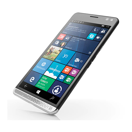
Product description Category Description Product Name HP Elite x3 Processor and chipset Qualcomm® MSM 8996 Snapdragon 820 Quad Core Processor Graphics Adreno 530 GPU (integrated in the MSM 8996 processor) Panel 5.96 inch (15.14 cm), WQHD 2560x1440 AMOLED, 16:9 aspect ratio, 494 PPI, Gorilla Glass4 with anti-smudge coating. - Page 6 Video out via USB Type-C power connector and charging port, DisplayPort Alternate Mode ● POGO pin connector Docking HP Elite x3 Desk Dock HP Elite x3 Lap Dock Power requirements Battery Non-removable, 3.85 V, Pack capacity is 15.98 Wh Long Life Battery (LLB).
-
Page 7: External Component Identification
External component identification Front Front... - Page 8 To access this guide: ▲ Swipe up from the middle of the Start screen, tap HP Device Hub, and then tap User Guide. Select your language if prompted to do so, and then tap Regulatory, Safety and Environmental Notices. IMPORTANT: You must be connected to the Internet to access the latest version of the document.
- Page 9 Component Description Volume up button Increases speaker volume incrementally while you hold down the button. The volume status bar appears when you press this button. Volume down button Decreases speaker volume incrementally while you hold down the button. The volume status bar appears when you press this button.
-
Page 10: Back
Tap Flashlight again to turn off the flashlight. Fingerprint reader Allows a fingerprint recognition to unlock your device instead of a PIN. NOTE: The fingerprint reader may require additional software. For more information, go to http://www.hp.com/support. Chapter 2 External component identification... - Page 11 To access this guide: ▲ Swipe up from the middle of the screen, tap HP Device Hub, and then tap User Guide. Select your language if prompted to do so, and then tap Regulatory, Safety and Environmental Notices. IMPORTANT: You must be connected to the Internet to access the latest version of the document.
-
Page 12: Labels
IMPORTANT: Check the following locations for the labels described in this section: the HP Device Hub app, the electronic regulatory labels, the back of the device, and the device box. To access the HP Device Hub: ▲... -
Page 13: Illustrated Parts Catalog
Illustrated parts catalog Major components NOTE: HP continually improves and changes product parts. For complete and current information on supported parts for your device, go to http://partsurfer.hp.com, select your country or region, and then follow the on-screen instructions. Item Component Spare part number 5.96 inch, Wide Quad High Definition (WQHD) 2560x1440 Active Matrix Organic LED... - Page 14 Item Component Spare part number NOTE: If you replace the battery, you must also replace the chassis. Front camera, 8 MP (includes cable) 853377-001 Iris camera, 2.4 MP (includes cable) 900262-001 Rear camera, 16 MP (includes cable) 853376-001 System board, includes audio board and thermal pads For use in North America, equipped with Windows 10 Mobile, Snapdragon 820 quad 903660-001 ●...
-
Page 15: Miscellaneous Parts
Miscellaneous parts Component Spare part number AC adapter, 10 W, non-power factor correcting (NPFC), non-Smart USB A, wall mount 838274-001 Cable, USB Type-C to USB A 858604-001 Case, silicone protective 905634-001 Device, black ● For use in Americas region, 1 SIM card 912853-001 ●... -
Page 16: Removal And Replacement Preliminary Requirements
Compressed air ● Lint- and static-free cloths NOTE: The following items must be approved for use with the HP Elite X3. Contact your HP service contact for additional information. ● Glue machine and the glue for that machine Display panel adhesive alignment fixture ●... -
Page 17: Plastic Parts
Plastic parts CAUTION: Using excessive force during disassembly and reassembly can damage plastic parts. Use care when handling the plastic parts. Apply pressure only at the points designated in the maintenance instructions. Cables and connectors CAUTION: When servicing the device, be sure that cables are placed in their proper locations during the reassembly process. - Page 18 Typical electrostatic voltage levels Relative humidity Event Motions of bench worker 6,000 V 800 V 400 V Removing DIPS from plastic tube 2,000 V 700 V 400 V Removing DIPS from vinyl tray 11,500 V 4,000 V 2,000 V Removing DIPS from Styrofoam 14,500 V 5,000 V 3,500 V...
-
Page 19: Packaging And Transporting Guidelines
Packaging and transporting guidelines Follow these grounding guidelines when packaging and transporting equipment: To avoid hand contact, transport products in static-safe tubes, bags, or boxes. ● ● Protect ESD-sensitive parts and assemblies with conductive or approved containers or packaging. Keep ESD-sensitive parts in their containers until the parts arrive at static-free workstations. ●... - Page 20 Equipment guidelines Grounding equipment must include either a wrist strap or a foot strap at a grounded workstation. ● When seated, wear a wrist strap connected to a grounded system. Wrist straps are flexible straps with a minimum of one megohm ±10% resistance in the ground cords. To provide proper ground, wear a strap snugly against the skin at all times.
-
Page 21: Removal And Replacement Procedures
NOTE: HP continually improves and changes product parts. For complete and current information on supported parts for your device, go to http://partsurfer.hp.com, select your country or region, and then follow the on-screen instructions. This chapter provides removal and replacement procedures for authorized service provider only parts. -
Page 22: End Cap
End cap Description Spare part number End cap, chrome 903689-001 Speaker mesh cap 904363-001 Remove the end cap: ▲ Insert a spudger in the gap between the end cap and the device, and then remove the end cap. If you need to replace the speaker mesh cap: ▲... -
Page 23: Display Panel Assembly
Reverse the steps to replace the end cap. NOTE: A small amount of glue may be required to secure the end cap. Contact your HP service contact for additional details. Display panel assembly Description Spare part number 5.96 inch, WQHD 2560x1440 AMOLED, touchscreen display panel assembly, includes OLED panel,... - Page 24 CAUTION: You will need heat protective gloves or a way to safely move the device once it is heated. IMPORTANT: Once the device is heated, you will need to work quickly to remove the display panel assembly before the glue hardens again. NOTE: You will need a stand to hold the display or have way to secure the display panel assembly at a 90 degree angle after you release the left side of the display.
- Page 25 Using the suction in the middle, lift the display (1) to open it. The display flex cable is still connected on the right side. Use a spudger (2) to break the adhesive at the top of the device. Lift the left side (1) of the display assembly. The display flex cable is still connected on the right side. Remove the two M1.6_L4.35 Phillips screws (2) securing the battery flex retaining bracket.
- Page 26 Set up the glue machine. Program the glue machine to dispense glue to match the Glue Path Golden Sample provided by your HP service contact. Make sure the glue tube is installed per the manufacturer’s instructions. NOTE: As many as 10 samples of the glue path could be required. Each sample must fit the following criteria: ●...
- Page 27 Remove the device side of the protective film from the display pressure-sensitive adhesive. With the removed adhesive side up, insert the display pressure-sensitive adhesive into the display panel adhesive alignment fixture. NOTE: Make sure the device is oriented to match the display pressure-sensitive adhesive orientation.
- Page 28 Apply grounding tape (7) on the display flex retention bracket and chassis. Align the display. Align the display assembly with the guides in the display kit alignment fixture. Press the display assembly on the glue on the device. Visually confirm the display assembly is in the correct location. Use a lint- and static-free cloth with 70 percent isopropyl alcohol to remove any excess glue.
- Page 29 Use 7 pieces of 0.05 mm thermal conductivity adhesive tape (heat tape) to secure the display assembly in place. Allow the glue to cure. Insert the device in the display pressing fixture. Insert the Torx screws in the order shown with 1.3±0.5 kgf·cm. NOTE: Refer to the glue specifications for additional acceptable environments.
- Page 30 Allow glue to dry at least 4 hours in an environment of 75%–85% humidity and 25.0° C (77.0° F). Remove the screws in the order shown. Remove the device from the display pressing fixture. Remove the 7 pieces of tape. Clean the glue Visually inspect the glue locations along all of the edges.
-
Page 31: Chassis And Battery Removal
Chassis and battery removal Description Spare part number Chassis, pre-assembled, includes upper and lower speakers, battery, lens, adhesive, and thermal pad 903685-001 NOTE: If you replace the chassis, you must also replace the battery. Battery, 1 C, 15 WHr, LI non-user removable 838524-005 NOTE: If you replace the battery, you must also replace the chassis. - Page 32 Gently remove the chassis. You can use suction cups or a thin metal tool to help remove the chassis. IMPORTANT: Do not remove the battery from the chassis. If you are installing a new battery or a new chassis, you must replace both the chassis and battery with a new chassis and new battery. To install a new battery: Remove the bottom protective film from the battery adhesive, and then attach the battery adhesive to the battery location (1) on the new chassis.
- Page 33 Attach the battery (3) to the chassis. To replace the chassis, place it in the back cover, replace the 15 T5 screws, and then reverse the remaining prerequisite procedures to complete installation. Chassis and battery removal...
-
Page 34: Rear Camera
Rear camera Description Spare part number Rear camera, 16 MP (includes cable) 853376-001 Before removing the rear camera, follow these steps: Disconnect the power from the device by unplugging the power cord from the device. Turn off the device. If you are unsure whether the device is off, turn the computer on, and then shut it down through the operating system. - Page 35 Audio-out (headphone)/Audio-in (microphone) combo jack Rear camera Use a spudger to gently remove the rear camera from the chassis. Reverse this procedure to install the rear camera. Rear camera...
-
Page 36: System Board
System board Description Spare part number System board, includes audio board and thermal pads: ● For use in North America, equipped with Windows 10 Mobile, Snapdragon 820 quad core processor, 903660-001 4 GB, 64 G eMMC ● For use in the rest of the world, equipped with Windows 10 Mobile, Snapdragon 820 quad core 905637-001 processor, 4 GB, 64 G eMMC Before removing the system board, follow these steps:... - Page 37 Disconnect the main antenna cable (4) from the system board. NOTE: Note the routing of the cable. Remove the four T5 screws (1) securing the system board. Lift the system board from the back cover. NOTE: The fingerprint reader/NFC sensor flex cable is connected under the system board. It is next to the power button, and is routed under the antenna wire.
-
Page 38: Front Camera
Front camera Description Spare part number Front camera, 8 MP (includes cable) 853377-001 Before removing the front camera, follow these steps: Disconnect the power from the device by unplugging the power cord from the device. Turn off the device. If you are unsure whether the device is off, turn the computer on, and then shut it down through the operating system. -
Page 39: Iris Camera
Iris camera Description Spare part number Iris camera, 2.4 MP (includes cable) 900262-001 Before removing the iris camera, follow these steps: Disconnect the power from the device by unplugging the power cord from the device. Turn off the device. If you are unsure whether the device is off, turn the computer on, and then shut it down through the operating system. -
Page 40: Antenna Board
Antenna board Description Spare part number Antenna board 903688-001 Before removing the antenna board, follow these steps: Disconnect the power from the device by unplugging the power cord from the device. Turn off the device. If you are unsure whether the device is off, turn the computer on, and then shut it down through the operating system. -
Page 41: Back Cover
Back cover The back cover remains after disassembling the device. The back cover is pre-assembled and includes parts that cannot be removed: audio-out (headphone)/audio-in (microphone) combo jack, USB Type-C power connector and charging port, NFC module, rear charging, heat spreader, lens adhesive, and WWAN/WLAN. The following table provides back cover spare part numbers. -
Page 42: Specifications
The device operates on DC power, which can be supplied by an AC or a DC power source. The AC power source must be rated at 100-240 V, 50/60 Hz, 0.3-1.0 A. NOTE: The HP adapter included with the device is recommended for charging the device. Temperature Operating 0°C to 35°C... -
Page 43: Power Adapter Requirements
Power adapter requirements The wide-range input feature of the device permits it to operate from any line voltage from 100 to 120 volts AC, or from 220 to 240 volts AC. The 2-conductor power adapter included with the device meets the requirements for use in the country or region where the equipment is purchased. - Page 44 Country/region Accredited agency Norway NEMKO The People's Republic of China Saudi Arabia SASO Singapore South Africa SABS South Korea Sweden SEMKO Switzerland Taiwan BSMI Thailand TISI The United Kingdom ASTA The United States Chapter 7 Power adapter requirements...
-
Page 45: Recycling
Follow the local laws and regulations in your area for battery disposal. HP encourages customers to recycle used electronic hardware, HP original print cartridges, and rechargeable batteries. For more information about recycling programs, see the HP Web site at http://www.hp.com/recycle. -
Page 46: Index
Index iris camera ambient light sensor, identifying 4 device, spare part number 11 removal 35 antenna board display kit pressing fixture spare part number 10, 35 removal 36 spare part number 19 iris camera, identifying 4 spare part number 10, 36 display panel assembly audio, product description 1 removal 19... - Page 47 regulatory information wireless networking, product operating system, product locating 8 description 1 description 2 regulatory label 8 WLAN antennas, identifying 6 wireless certification labels 8 WLAN device 8 WLAN label 8 packaging guidelines 15 workstation guidelines 15 plastic parts, service screw kit, spare part number 11 WWAN antennas, identifying 6 considerations 13...