Table of Contents
Quick Links
Converter Module
Thank you for purchasing the programmable controller.
Prior to use, please read this and relevant manuals thoroughly to
fully understand the product.
© 2008 MITSUBISHI ELECTRIC CORPORATION
Digital-Analog
AJ65SBT2B-64DA
MODEL AJ65S-64DA-U-HW
MODEL
CODE
IB(NA)-0800418-E(1612)MEE
User's Manual
(Hardware)
13JY75
Table of Contents

Related Manuals for Mitsubishi Electric AJ65SBT2B-64DA


Summary of Contents for Mitsubishi Electric AJ65SBT2B-64DA
- Page 1 Digital-Analog Converter Module User’s Manual (Hardware) AJ65SBT2B-64DA Thank you for purchasing the programmable controller. Prior to use, please read this and relevant manuals thoroughly to fully understand the product. MODEL AJ65S-64DA-U-HW MODEL 13JY75 CODE IB(NA)-0800418-E(1612)MEE © 2008 MITSUBISHI ELECTRIC CORPORATION...
-
Page 2: Safety Precautions
SAFETY PRECAUTIONS (Read these precautions before using this product.) Before using this product, please read this manual and the relevant manuals carefully and pay full attention to safety to handle the product correctly. The instructions given in this manual are concerned with this product. For the safety instructions of the programmable controller system, please read the CPU module user's manual. - Page 3 [Design Precautions] WARNING Configure a safety circuit so that the safety of the overall system is maintained even if an external power failure or a programmable controller failure occurs. Incorrect output or malfunction can lead to an accident. (1) The status of analog output changes depending on the setting of various functions that control the analog output.
- Page 4 [Installation Precautions] CAUTION Use the module in an environment that meets the general specifications given in this manual. Operating it in any other environment may cause an electric shock, fire, malfunction, product damage or deterioration. For protection of the switches, do not remove the cushioning material before installation.
- Page 5 [Wiring Precautions] CAUTION Shut off the external power supply for the system in all phases before wiring. Failure to do so may result in damage to the product. Always ground the FG terminal to the protective ground conductor. Failure to do so may result in malfunctions. Be sure to tighten any unused terminal screws within a tightening torque range.
- Page 6 [Wiring Precautions] CAUTION Do not install the control lines or communication cables together with the main circuit lines or power cables. Failure to do so may result in malfunction due to noise. When disconnecting the cables from the module, do not hold and pull the cable part.
- Page 7 PRÉCAUTIONS DE SÉCURITÉ (Lire ces précautions avant toute utilisation du produit.) Avant d'utiliser ce produit, lire attentivement ce manuel ainsi que les manuels auxquels il renvoie, et toujours considérer la sécurité comme de la plus haute importance en manipulant le produit correctement. Les précautions à...
- Page 8 [Précautions lors de la conception] AVERTISSEMENT Constituer un circuit de sécurité capable de maintenir la sécurité de l'ensemble du système même en cas de panne de courant sur une alimentation externe ou de défaillance d'un automate programmable. Une sortie erronée ou un dysfonctionnement peuvent être à l'origine d'un accident.
- Page 9 [Précautions d'installation] ATTENTION Utiliser le module dans un environnement en conformité avec les spécifications générales que présente ce manuel. Son utilisation dans tout autre environnement expose au risque d'électrocution, de départ de feu, de dysfonctionnement ou de détérioration du produit. Pour la protection des commutateurs, ne pas enlever le matériau de rembourrage avant l'installation.
- Page 10 [Pécautions de câblage] ATTENTION Couper l'alimentation externe du système sur toutes les phases avant de commencer à câbler. Faute quoi, le produit risquerait d'être endommagé. Toujours mettre à la masse la borne FG sur le conducteur de protection de terre. Faute de quoi, il y a risque de dysfonctionnement.
- Page 11 [Pécautions de câblage] ATTENTION Ne pas entremêler les lignes de commandes ou câbles de communication avec les lignes des circuits principaux ou les câbles d'alimentation. Faute de quoi, il y a risque de dysfonctionnement par un bruit. Pour débrancher les câbles du module, ne pas tirer sur le câble lui-même. Débrancher les câbles après avoir desserré...
- Page 12 [Précautions de mise au rebut] ATTENTION Lors de sa mise au rebut, ce produit doit être traité comme un déchet industriel. A-11...
- Page 13 CONDITIONS OF USE FOR THE PRODUCT (1) Mitsubishi programmable controller ("the PRODUCT") shall be used in conditions; i) where any problem, fault or failure occurring in the PRODUCT, if any, shall not lead to any major or serious accident; and ii) where the backup and fail-safe function are systematically or automatically provided outside of the PRODUCT for the case of any problem, fault or failure occurring in the PRODUCT.
- Page 14 Notwithstanding the above, restrictions Mitsubishi may in its sole discretion, authorize use of the PRODUCT in one or more of the Prohibited Applications, provided that the usage of the PRODUCT is limited only for the specific applications agreed to by Mitsubishi and provided further that no special quality assurance or fail-safe, redundant or other safety features which exceed the general specifications of the PRODUCTs are required.
- Page 15 This manual confers no industrial property rights or any rights of any other kind, nor does it confer any patent licenses. Mitsubishi Electric Corporation cannot be held responsible for any problems involving industrial property rights which may occur as a result of using the contents noted in this manual.
-
Page 16: Table Of Contents
CONTENTS 1. OVERVIEW ....................1 2. SPECIFICATIONS..................2 2.1 General Specifications ................2 2.2 Performance Specifications..............4 3. PART NAMES AND SETTINGS..............6 3.1 Part names ....................6 4. LOADING AND INSTALLATION ..............9 4.1 Handling Precautions ................9 5. DATA LINK CABLE WIRING ................ 10 5.1 Wiring Precautions ................. - Page 17 The following manual is also related to this product. If necessary, place an order. Related Manual Manual Number Manual name (Model code) Digital-Analog Converter Module Type AJ65SBT2B-64DA User's SH-080768ENG Manual (13JZ19) COMPLIANCE WITH EMC AND LOW VOLTAGE DIRECTIVES (1) Method of ensuring compliance...
-
Page 18: Overview
1. OVERVIEW This user's manual explains the specifications, names of the components and wiring for the type AJ65SBT2B-64DA digital-analog converter module (hereafter AJ65SBT2B-64DA) which are used as a remote device station of a CC-Link system. -
Page 19: Specifications
2. SPECIFICATIONS 2.1 General Specifications The general specifications for the AJ65SBT2B-64DA are shown in the following table. Table 2.1 General specifications Item Specification Operating ambient temperature 0 to 55 Température 0 à 55 ambiante de fonctionnement Storage ambient -20 to 75... - Page 20 Do not use or store the programmable controller under pressure higher than the atmospheric pressure of altitude 0m. Doing so may cause malfunction. When using the programmable controller under pressure, please consult your local Mitsubishi Electric representative.
-
Page 21: Performance Specifications
2.2 Performance Specifications The performance specifications for the AJ65SBT2B-64DA are shown in the following table. Table 2.2 Performance specifications Item AJ65SBT2B-64DA 16-bit signed binary Voltage Digital input (-12288 to 12287, -16384 to 16383, -288 to 12287) value Current 16-bit signed binary(-288 to 12287) - Page 22 Table 2.2 Performance specifications Item AJ65SBT2B-64DA Noise voltage : 500Vp-p, tested by noise simulator of noise width Noise immunity of 1 s and noise frequency of 25 to 60Hz Communication part, module 7-point 2-piece terminal block power supply 5.2 Tightening torque: 0.59 to 0.88N•m...
-
Page 23: Part Names And Settings
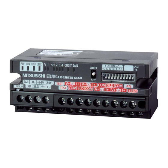
3. PART NAMES AND SETTINGS 3.1 Part names This section explains the names of the components for the AJ65SBT2B- 64DA. Figure 3.1 Appearance of the AJ65SBT2B-64DA... - Page 24 Table 3.1 Part names Name Description On: Power supply on PW LED Off: Power supply off Normal operation Flashing: 0.1s intervals indicate an output range setting error. Normal 0.5s intervals indicate a digital value setting mode error. Off: Indicates that 24V DC power supply interrupted, watchdog timer error occurred, write error for flash memory occured.
- Page 25 L TER. (Line Turned ON to validate the terminating resistor stored in the AJ65SBT2B- Termination) 64DA. switch Used when the AJ65SBT2B-64DA is used on the network edge. The transmission speed is automatically set depending on the setting of the master module.
-
Page 26: Loading And Installation
When installing a DIN rail, tighten the screws at a pitch of 200mm or less. (3) When mounting the AJ65SBT2B-64DA to the DIN rail, press with your finger the centerline of the DIN rail hook at the bottom of the module until it clicks. -
Page 27: Data Link Cable Wiring
5.2 CC-Link Dedicated Cable Connection Method Méthode de raccordement par câble dédié CC-Link The following shows how to connect the AJ65SBT2B-64DA to a master module and a remote module with CC-Link dedicated cables. Le schéma ci-dessous explique comment connecter un AJ65SBT2B- 64DA à... -
Page 28: Connection Of Terminating Resistor
(c) The built-in terminating resistor cannot be used in the following cases. Wire a terminating resistor (110 or 130 ). • A CC-Link system is configured using CC-Link cables of 130 . • The AJ65SBT2B-64DA may be replaced during data link. -
Page 29: Wiring
The precautions when performing external wiring are as follows: (1) Use separate cables for the AC control circuit and the external output signals of the AJ65SBT2B-64DA or the external power supply to avoid the influence of the AC side surges and induction. -
Page 30: Wiring With External Devices
6.2 Wiring with External Devices Câblage à l'aide de périphériques externes (1) For voltage output Pour sortie de tension Motor drive module, etc. conversion Filter Figure 6.1 Wiring for voltage output English French D/A conversion Conversion N/A Filter Filtre Motor drive module, etc. Module d'entraînement du moteur, etc. - Page 31 (2) For current output Pour sortie de courant Motor drive module, etc. conversion Filter Figure 6.2 Wiring for current output Use a twisted two core shielded wire for the power wire. If there is noise or ripples in the external wiring, connect a 0.1 to 0.47 F capacitor (25V or higher voltage-resistant product) to the input terminals of the external device.
-
Page 32: External Dimensions
7. EXTERNAL DIMENSIONS The external dimensions of the AJ65SBT2B-64DA is shown below. 109.5±0.5 2-4.5 5.1 M4 DIN rail center Unit: mm... - Page 33 MEMO...
- Page 34 MEMO...
- Page 35 MEMO...
- Page 36 20 Waterford Office Park, 189 Witkoppen Road, Avenida Adelino Cardana, 293, 21 andar, Fourways, South Africa Bethaville, Barueri SP, Brazil Tel : +27-11-658-8100 Tel : +55-11-4689-3000 Germany MITSUBISHI ELECTRIC EUROPE B.V. German China MITSUBISHI ELECTRIC AUTOMATION (CHINA) Branch LTD. Mitsubishi-Electric-Platz 1, 40882 Ratingen, No.1386 Hongqiao Road, Mitsubishi Electric...