Epson DM-D210 Technical Reference Manual
Hide thumbs
Also See for DM-D210:
- Specification sheet (2 pages) ,
- Start here (2 pages) ,
- User manual (87 pages)
Table of Contents
Quick Links
See also:
User Manual, Installation Manual
Technical Reference Guide
Product Overview
Describes features and general specifications for this
product.
Setup
Describes how to install and set this product.
Handling
Describes the basic usage of this product.
Application Development Information
Describes how to control this product and information
necessary for developing applications.
Appendix
Describes the specifications of the product, connectors,
and serial cables, as well as the character code table.
M00035601
Rev. B
Table of Contents

Related Manuals for Epson DM-D210


Summary of Contents for Epson DM-D210
-
Page 1: Product Overview
Technical Reference Guide Product Overview Describes features and general specifications for this product. Setup Describes how to install and set this product. Handling Describes the basic usage of this product. Application Development Information Describes how to control this product and information necessary for developing applications. - Page 2 Neither is any liability assumed for damages resulting from the use of the information contained herein. Neither Seiko Epson Corporation nor its affiliates shall be liable to the purchaser of this product or third par- ties for damages, losses, costs, or expenses incurred by the purchaser or third parties as a result of: accident, misuse, or abuse of this product or unauthorized modifications, repairs, or alterations to this product, or (excluding the U.S.) failure to strictly comply with Seiko Epson Corporation’s operating and maintenance...
-
Page 3: For Safety
For Safety Key to Symbols The symbols in this manual are identified by their level of importance, as defined below. Read the following carefully before handling the product. You must follow warnings carefully to avoid serious bodily injury. WARNING Provides information that must be observed to prevent damage to the equipment or loss of data. ... -
Page 4: Warnings
Shut down your equipment immediately if it produces smoke, a strange odor, or unusual noise. Continued use may lead to fire. Immediately unplug the equipment and contact your dealer or a Seiko Epson service center for advice. Never attempt to repair this product yourself. Improper repair work can be dangerous. -
Page 5: Restriction Of Use
Aim of the Manual This manual provides the development engineers with necessary information for developing, designing, install- ing the system using DM-D110/DM-D210 as well as for developing and designing the applications. Manual Content The manual is made up of the following sections:... -
Page 6: Table Of Contents
Options....................................11 ■ Part Names ..........................12 DM-D110..................................... 12 DP-110 ....................................12 DM-D110 for TM-T88V-DT ............................13 DM-D210..................................... 14 DP-210 ....................................14 ■ System Outline........................15 USB (Self Powered)................................15 USB (Bus Powered): Computer............................ 15 USB (Bus Powered): TM Intelligent Printer......................16 Serial (Stand-Alone) ................................ - Page 7 Serial (Y-type) ..................................24 Serial (USB controlled)..............................25 ■ Dip Switch Settings......................26 Settings by connection patterns ..........................26 Setting method.................................27 DIP Switch 1 Functions..............................28 ■ Attaching the Product......................29 DP-110....................................30 DP-210....................................34 DP-502 (TM-H6000IV/TM-U675) ..........................37 DP-502 (TM-H6000IV-DT)..............................43 DP-502 (TM-U950) ................................49 DP-502 (Attaching on the counter) ...........................52 DP-503 (TM-H5000II)...............................55 DM-D110 for TM-T88V-DT.............................57 ■...
- Page 8 ■ Precautions when using the serial (USB controlled) ............. 78 Appendix ......................79 ■ Product Specifications ......................79 DM-D110..................................... 79 DM-D210..................................... 84 Environmental Conditions ............................87 ■ DP-110/DP-210 Connector Specifications............... 88 ■ Serial Cable Specifications ....................94 ■ Character Code Tables......................96 Common to All Pages..............................
-
Page 9: Product Overview
Product Overview This chapter describes features and specifications of the DM-D110/DM-D210. Features DM-D110/DM-D210 is a customer display for displaying characters. The main features of this product are as follows. Display 20 digit x 2 lines dot matrix for displaying half-width characters.... -
Page 10: Product Structure
The following shows the models for the customer display unit. DM-D110 RS-232/USB model RS-232 model USB model DM-D110 for TM-T88V-DT model (For TM-T88V-DT) DM-D210 RS-232/USB model RS-232 model Accessories Model Accessory Start Here RS-232/USB model ... -
Page 11: Options
DP-110 without Interface Board DM-D110 stand (without an interface board) Use this when installing near the USB bus power and the printer using a Y connection. DP-105 Extension pole to be used with DP-110 DM-D210 DP-210 DM-D210 stand (with interface board) -
Page 12: Part Names
Part Names DM-D110 Dip switch (rear side) Screen Power Switch (bottom side of the display) *2 USB cable *1 *2 Ferrite core (with a cap RS-232 cable (with a cap 1 For the USB model, the power switch, ferrite core, USB cable cap and RS-232 cable are not included. 2 For the RS-232 model, the USB cable, RS-232 cable cap and ferrite core are not included. -
Page 13: Dm-D110 For Tm-T88V-Dt
Chapter 1 Product Overview DM-D110 for TM-T88V-DT Ferrite core Dip switch (rear side) Straight pole Screen Base USB cable (with a cap L-shaped pole They may not be supplied for DM-D110 for TM-T88V-DT depending on when the product is shipped. -
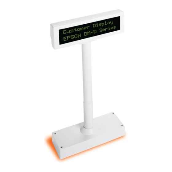
Page 14: Dm-D210
DM-D210 Screen Power Switch (bottom side of the display) Dip switch (bottom side of the display) USB cable (with a cap) Ferrite core RS-232 cable (with a cap For the RS-232 model, the USB cable, RS-232 cable cap and ferrite core are not included. -
Page 15: System Outline
Connect to a USB bus that has sufficient power supply capability. Otherwise brightness may decline. Be careful when connecting to a laptop computer or a USB hub. DM-D110: You can use the RS-232/USB and USB models. DM-D210: You cannot use it. -
Page 16: Usb (Bus Powered): Tm Intelligent Printer
Connect this product’s USB cable to the TM intelligent printer. Power is supplied from the TM intelligent printer. TM-T88V-DT (Attach DM-D110 for TM-T88V-DT) TM-T88V-DT DM-D110 for TM-T88V-DT TM-DT series/TM-i series TM Intelligent Printer DM-D110 DM-D110: You can use the RS-232/USB and USB models. DM-D210: You cannot use it. -
Page 17: Serial (Stand-Alone)
Chapter 1 Product Overview Serial (Stand-Alone) Connect DP-110/DP-210 to the computer using a serial cable. Computer DM-D110/DM-D210 Serial PS-180 Serial (Pass-through) Connect the serial interface TM printer to the DP-110/DP210 connected to the computer using a serial connec- tion. The power to the TM printer is supplied from DP-110/DP-210 via a power extension cable. -
Page 18: Serial (Y-Type)
Serial (Y-type) Connect this product’s RS-232 cable to the TM printer DM-D connector, and then connect the TM printer and the computer using a serial cable. Power is supplied from the TM printer. TM Printer DM-D110/DM-D210 Computer PS-180 Serial... -
Page 19: Serial (Usb Controlled)
Connect this product’s RS-232 cable to the DM-D connector for the TM printer (to which UB-U01III or UB- U02III is attached), and then connect the TM printer and the computer using the USB cable. Power is supplied from the TM printer. TM Printer Computer UB-U01III/ PS-180 UB-U02III DM-D110/DM-D210... -
Page 20: Connection Patterns By Options
✔ Serial (Pass-through) ✔ ✔ ✔ ✔ Serial (Y-type) ✔ ✔ ✔ ✔ Serial (USB controlled) Attached to TM-H6000IV-DT DM-D210 Option Connection Pattern DP-210 DP-502 DP-503 ✔ USB (Self Powered) ✔ Serial (Stand-Alone) ✔ Serial (Pass-through) ✔ ✔ ✔... -
Page 21: Setup
Chapter 2 Setup Setup This chapter explains the installation and setting operations necessary to use this product. Setup Flow This section explains the setup flow by connection patterns. USB (Self Powered) Preparation Option (DP-110 /DP-210) AC adapter Power cord Dip Switch Settings (page Set the communication speed to 115200 bps. -
Page 22: Usb (Bus Powered): Computer
USB (Bus Powered): Computer Power is supplied from the computer USB port. Preparation Option (DP-110 Dip Switch Settings (page Set the communication speed to 115200 bps. Attaching the Product (page Connecting Cables (page Installing the DM-D110 Virtual COM Port Driver to the Computer For details, see the manual supplied with the DM-D110 Virtual COM Port Driver. -
Page 23: Serial (Stand-Alone)
Chapter 2 Setup Serial (Stand-Alone) Preparation Option (DP-110 /DP-210) AC adapter Power cord Serial cable (page Dip Switch Settings (page Attaching the Product (page Connecting Cables (page When extending the length of the support, prepare the option of DP-105. Serial (Pass-through) Preparation ... -
Page 24: Serial (Y-Type)
Serial (Y-type) Preparation DM-D110: Select from the following options DP-110 DP-502 DP-503 DM-D210: Select from the following options DP-210 DP-502 DP-503 TM Printer (with DM-D connector, Serial interface) AC adapter ... -
Page 25: Serial (Usb Controlled)
Serial (USB controlled) Preparation DM-D110: Select from the following options DP-110 DP-502 DP-503 DM-D210: Select from the following options DP-210 DP-502 DP-503 TM Printer (with UB-U01III or UB-U02III) AC adapter ... -
Page 26: Dip Switch Settings
Serial (USB controlled) Set the communication speed to 19200 bps. TM Intelligent Printer (ePOS-Device) Match the serial communication settings for the TM intelligent printer’s EPSON TMNet WebConfig and this product. TM-DT Series (Windows) Match the serial communication settings for the TM-DT Series and this product. -
Page 27: Setting Method
Turn off the power of the this product and system, and remove cable. Remove the DIP switch cover. DM-D110 DM-D210 8 9 10 DIP Switch Cover Change each setting of the switches Refer to "DIP Switch 1 Functions"... -
Page 28: Dip Switch 1 Functions
DIP Switch 1 Functions The following explains the DIP switch functions. DSW1 No. Function Default Setting Received Error Data Ignore Ignore "?" Display Receive Data Length 7 bit 8 bit Parity With Parity No Parity Parity Selection Even Communication Speed Refer to "... -
Page 29: Attaching The Product
Use the optional DP-502 to attach DM-D110 to TM-H6000IV-DT. page 43 Use the optional DP-502 to attach DM-D110/DM-D210 to TM-U950. page 49 Use the optional DP-502 to attach DM-D110/DM-D210 to the counter. page 52 DP-503 Use the optional DP-503 to attach DM-D110/DM-D210 to TM-H5000II. -
Page 30: Dp-110
DP-110 Checking the accessories Check the DP-110 parts. Plate DP-110 Extension power cable RS-232C connector installation screw (millimeter type) Checking the accessories of DP-105 Check the DP-105 parts. Affixing tapes Extension support... -
Page 31: Jumper Setting
Chapter 2 Setup Setting the DP-110 Connector installation screw Inch-type hexagonal lock screws are installed in the connector for serial cable connection of DP-110. If millimeter-type lock screws are needed, use the millimeter-type lock screws of the accessory. Notch (one or more lines) inch-type millimeter-type Installation screw... - Page 32 Installing to the DP-110 Because the illustration used here is for the RS-232/USB model, there are 2 cables. The USB model and RS-232 model have 1 cable. Pass the cable for the DM-D110 through the DP-110. When extending the length of the DP110, attach the extension support (DP-105) to the DP-110.
- Page 33 Chapter 2 Setup Connect the cable to DP-110, computer, and TM printer to match the constructed environment. (See "Connecting" on page Arrange the cables as shown below. Put the cables inside the DP-110. For the RS-232/USB model, the end of the connector of the unused cable should be capped, and then bundled to be stored inside DP-110.
-
Page 34: Dp-210
DP-210 Checking the accessories Check the DP-210 parts. DP-210 Support Extension support RS-232C connector installation screw Extension power cable (millimeter type) Setting the DP-210 Connector installation screw Inch-type hexagonal lock screws are installed in the connector for serial cable connection of DP-210. If millimeter-type lock screws are needed, use the millimeter-type lock screws of the accessory. - Page 35 When extending the length of the DP-210, attach the extension support to the DP- 210. When using the extension support Insert the tab on the DM-D210 (or the extension support) into the hole on the DP-210 until you feel it click.
- Page 36 Connect the cable to DP-210, computer, and TM printer to match the constructed environment. (See "Connecting" on page Arrange the cables as shown below. Put the cables inside the DP-210. For the RS-232/USB model, the end of the connector of the unused cable should be capped, and then bundled to be stored inside DP-110.
-
Page 37: Tm-H6000Iv/Tm-U675)
Chapter 2 Setup DP-502 (TM-H6000IV/TM-U675) Checking the accessories Check the DP-502 parts. When attaching to the TM-H6000IV/TM-U675, use the following parts. Angle fixing screw Fixing plate B Stopper Fixing screw for stopper Rubber feet (small) Fixing screws for fixing plate B Fixing screws for rubber feet (small) Support B for extension... - Page 38 Installing to the TM-H6000IV/TM-U675 The illustrations used here are for DM-D110, but you can still use them as your reference for DM-D210. Because the illustration used here is for the RS-232/USB model, there are 2 cables. The USB model and RS-232 model have 1 cable.
- Page 39 Chapter 2 Setup Attach fixing plate B to the printer. Pass the cable for the this product through the hole on fixing plate A, and fix the cable at the bottom as shown below. For the RS-232/USB model, the end of the connector of the unused cable should be capped, and then bundled to be stored inside support.
- Page 40 Attach fixing plate A to the TM printer using the stopper. When you attach the stop- per, insert the projections on the stopper into the holes of fixing plate B. Fixing plate A can be attached on either side of the printer. (The illustration below shows fixing plate A attached to the right side of the printer.)
- Page 41 Chapter 2 Setup The horizontal rotation mechanism of fixing plate A can be adjusted. To secure the location of the display, set fixing plate A to either one of the following four positions and secure it with the angle fixing screw. The paper roll cover may not open if the position of the display is incorrect.
- Page 42 Store any excess cable in the support and attach the this product to fixing plate A. Connect the power cable of the printer. To avoid disconnection, hook the cable on the tabs on fixing plate B, as shown below.
-
Page 43: Tm-H6000Iv-Dt)
Chapter 2 Setup DP-502 (TM-H6000IV-DT) Checking the accessories Check the DP-502 parts. When attaching to the TM-H6000IV-DT, use the following parts. Fixing screw Angle fixing screw Fixing plate B Stopper for stopper Fixing screws for fixing plate B Support B for extension Fixing plate A Support C... - Page 44 Installing to the TM-H6000IV-DT Follow the instructions to install the DM-D110 (USB model) on the TM-H6000IV-DT using the exclusive DP- 502. Because the illustration used here is for the RS-232/USB model, there are 2 cables. The USB model and RS-232 model have 1 cable. Remove the connector cover of the TM-H6000IV-DT.
- Page 45 Chapter 2 Setup Use the 2 screws removed in Step 2 and the 2 included long screws. Be sure not to connect the cables before attaching the plate. Otherwise, the cables can be damaged. The illustration shows how to install the this product on the right side of the TM- H6000IV-DT.
- Page 46 Select the position where the this product is to be installed from A, B, C, or D.
- Page 47 Chapter 2 Setup Move the attached part in Step 4 so that screw holes indicated in the illustration are aligned with each other, according to the position you selected. Fix it with the included screw. Use the included extension pole if the pole is not long enough. Use the included extension pole if the pole is not long enough.
- Page 48 Put the USB cable through behind TM-H6000IV-DT as shown in the illustration. Install the this product to the attachment base. For the RS-232/USB model, the end of the connector of the unused cable should be capped, and then bundled to be stored inside support.
-
Page 49: Tm-U950)
Chapter 2 Setup DP-502 (TM-U950) Checking the accessories Check the DP-502 parts. When attaching to the TM-U950, use the following parts. [TM-U950 parts] Fixing screws for Rubber feet (square) plastic position [DP-502 parts] Fixing plate A Support B for extension Support C... - Page 50 Installing to the TM-U950 The illustrations used here are for DM-D110, but you can still use them as your reference for DM-D210. Because the illustration used here is for the RS-232/USB model, there are 2 cables. The USB model and RS-232 model have 1 cable.
- Page 51 Chapter 2 Setup Pass the cable for the this product through the hole on fixing plate A and fix the cable at the bottom as shown below. Adjust the length of the cable and secure fixing plate A to the printer with screws. Store any excess cable in the support, and attach the this product to fixing plate A....
-
Page 52: Attaching On The Counter)
DP-502 (Attaching on the counter) Checking the accessories Check the DP-502 parts. When attaching it on the counter, use the following parts. [DP-502 parts] Fixing plate A Support B for extension Support C Affixing tapes Fixing screws for Affixing tapes wood position... - Page 53 Attaching on the counter The illustrations used here are for DM-D110, but you can still use them as your reference for DM-D210. Because the illustration used here is for the RS-232/USB model, there are 2 cables. The USB model and RS-232 model have 1 cable.
- Page 54 Pass the cable for the this product through the hole on fixing plate A and fix the cable at the bottom as shown below. Peel off the affixing tapes and secure it to the mounting position. When using screws to attach it on the counter, use the screws to secure it to the mounting position. Connect the cable to the TM printer.
-
Page 55: Tm-H5000Ii)
Installing to the TM-H5000II The illustrations used here are for DM-D110, but you can still use them as your reference for DM-D210. Because the illustration used here is for the RS-232/USB model, there are 2 cables. The USB model and RS-232 model have 1 cable. - Page 56 Attach the base to the setting position on the TM printer and secure it with the screws. Pass the cable for the this product through the base. Insert the tab on the base into the hole on the support until you feel it click. For the RS-232/USB model, the end of the connector of the unused cable should be capped, and then bundled to be stored inside support.
-
Page 57: Dm-D110 For Tm-T88V-Dt
Chapter 2 Setup DM-D110 for TM-T88V-DT Checking the accessories Check the accessories of the DM-D110 for TM-T88V-DT. When attaching it on the printer, use the following parts. For models with a L-shaped pole Screws Base Customer display For models with a straight pole Pole Base Screws... - Page 58 Attaching on the DM-D110 for TM-T88V-DT For models with a L-shaped pole Detach the connector cover of the TM-T88V-DT. Detach the hooks from the TM-T88V-DT while pushing the bottom parts on both sides of the connec- tor cover inwards. Remove the U-shaped component from the connector cover. Attach the base on the TM-T88V-DT with the three screws.
- Page 59 Chapter 2 Setup Pass the USB cable of the customer display through the base. Align the dowel hole in the customer display and the dowel on the base to attach the customer display on the base. Align the hook for the connector cover of TM-T88V-DT with the groove on the back of TM-T88V-DT, and then push it in.
- Page 60 For models with a straight pole Detach the connector cover of the TM-T88V-DT. Detach the hooks from the TM-T88V-DT while pushing the bottom parts on both sides of the connec- tor cover inwards. Remove the U-shaped component from the connector cover. Attach the base on the TM-T88V-DT with the three screws.
- Page 61 Chapter 2 Setup With the end of the straight pole with a hole pointing downward, pass the USB cable of the customer display through the pole and base. Attach the pole with the customer display.
- Page 62 Align the dowel hole in the pole and the dowel on the base to attach the pole on the base. Align the hook for the connector cover of TM-T88V-DT with the groove on the back of TM-T88V-DT, and then push it in. When attaching the connector cover, always hold both sides.
-
Page 63: Connecting
Connect to the computer Remove the cap RS-232 cable Connect to the DM-D connector of DP-110/DP-210 DP-110 DM-D connector Connect the RS-232 cable of DM-D110/DM-D210 DP-210 Power supply connector Connect the AC adapter Extension power cable connec- Not used... -
Page 64: Usb (Bus Powered)
USB (Bus Powered) DM-D110 Ferrite core RS-232 cable USB cable Not connected Not connected DP-110 Computer/ TM Intelligent Printer Remove the cap DM-D110 USB cable Attach the ferrite core Connect to the computer/TM intelligent printer Do not remove the cap (factory default condition) RS-232 cable ... -
Page 65: Serial (Stand-Alone)
RS-232 cable Attach the ferrite core Connect to the DM-D connector of DP-110/DP-210 DP-110 DM-D connector Connect the RS-232 cable of DM-D110/DM-D210 DP-210 Power supply connector Connect the AC adapter Extension power cable connec- Not used... -
Page 66: Serial (Pass-Through)
RS-232 cable Attach the ferrite core Connect to the DM-D connector of DP-110/DP-210 DP-110 DM-D connector Connect the RS-232 cable of DM-D110/DM-D210 DP-210 Power supply connector Connect the AC adapter Extension power cable connec- Use the extension power cable and connect to the TM printer's... -
Page 67: Serial (Y-Type)
Power cord TM Printer DM-D110 Do not remove the cap (factory default condition) USB cable DM-D210 Not used (bundle inside DP-110/DP-210 or DP-502/DP-503) Remove the cap RS-232 cable Attach the ferrite core Connect to the TM printer's DM-D connector ... -
Page 68: Serial (Usb Controlled)
Power cord TM Printer DM-D110 Do not remove the cap (factory default condition) USB cable DM-D210 Not used (bundle inside DP-110/DP-210 or DP-502/DP-503) Remove the cap RS-232 cable Attach the ferrite core Connect to the DM-D connector on the interface side of the TM printer. -
Page 69: Handling
DM-D110 for TM-T88V-DT You can change the direction or angle of the display and L-shaped pole by moving them while holding TM- T88V-DT by hand. With a L-shaped pole With a straight pole 270 48 300 48 300 DM-D210 330 36... -
Page 70: Cleaning The Customer Display
Cleaning the customer display Turn off the this product as well as the connected system. Use a dry cloth or firmly wrung cloth to wipe off any stains on the this product. Do not use alcohol, benzine, thinner and other solvents; otherwise, the product may be damaged or the plastic parts may be broken. -
Page 71: Application Development Information
EPSON Advanced Printer Driver Ver.4 (APD4) ePOS-Print XML ePOS-Device XML is Epson's control command system for the customer display defined in XML. You can print from the socket communication environment or OS applications. For details of ePOS-Device XML, see the ePOS-Device XML User’s Manual. -
Page 72: Software And Manuals
OLE technology developed by Microsoft divides software into part blocks. Drivers Operating Software Description environment EPSON Advanced Printer Driver Windows printer driver that can display on the customer dis- Windows Ver.4 (APD4) play. You cannot send ESC/POS commands to the customer dis- play or monitor the status. -
Page 73: Manuals
Chapter 4 Application Development Information Manuals Software Description DM-D110/DM-D210 This manual. Technical Reference Guide Each TM printer's Technical Refer- TM printer's Technical Reference Guide explains about the necessary information for ence Guide developing, designing, installing the POS system using the TM printers, or for devel- oping and designing the printer applications. -
Page 74: Data Flow Of Serial Commands
Data flow of serial commands This section explains the data flow when using this product using a serial connection. Block Diagram DM-D110/DM-D210 CPU for display unit Level shifter RS-232 cable connector Modular-8 DP-110/DP-210 DM-D connector Modular-8 RXD (3) TXD (3) -
Page 75: Stand-Alone Connection
The data flow when the standalone connection is as follows. DP-110/DP-210 Computer DM-D110 DM-D210 Transmit data from the computer Transmit data to the computer Power supply When 1-2 of JP1 and JP2 are selected, the data from the computer is transmitted to the customer display and the data from the customer display is transmitted to the computer with the standalone connection. -
Page 76: Pass-Through Connection
The data flow when the pass-through connection is as follows. DP-110/DP-210 Computer DM-D110 DM-D210 Transmit data from the computer TM Printer Transmit data to the computer from the TM printer Transmit data to the TM printer Power supply ... -
Page 77: Y-Type Connection
Transmit data to the computer from the TM printer Transmit data to the TM printer TM Printer DM-D110 DM-D210 Power supply The data from the computer is transmitted to the TM printer and the same data is transmitted to the cus- tomer display with the y-type connection. -
Page 78: Precautions When Using The Usb Models
Precautions when Using the USB Models This section explains the usage precautions when using a USB connection (self powered and bus powered). Controlled environment Precautions ✔ ✔ ✔ When using the DM-D110 Virtual COM Port Driver, set the communication speed for the dip switch to 115200 bps. -
Page 79: Appendix
Appendix Appendix Product Specifications DM-D110 DM-D110 DM-D110 Model DM-D110 with DP-110 for TM-T88V-DT Display type Fluorescent tube display Number of characters displayed 40 characters (20 columns x 2 rows, 5 x 7 dot matrix) Display color Green (505 nm) Brightness 690 cd/m2 Character classes Alphanumeric: 95 characters... - Page 80 DM-D110 DM-D110 Model DM-D110 with DP-110 for TM-T88V-DT Tilt angle Maximum 48 (4 steps, 5 positions) Display: Horizontal rotation angle Maximum 90 Maximum 300 L-shaped pole: Maximum 270 Supplied Power supply Supplied by TM printer PS-180 (Option) or USB bus by TM-T88V-DT...
- Page 81 Appendix External Dimensions and Mass DM-D110 50.5 mm 165 mm Item Specification Display unit dimension 165 (W) x 50.5 (D) x 69 (H) mm {6.5 (W) x 1.99 (D) x 2.72" (H)} External dimensions 165 (W) x 50.5 (D) x 69 (H) mm {6.5 (W) x 1.99 (D) x 2.72" (H)} Mass Approximately 0.29 kg {Approximately 0.64 Ib} DM-D110 with DP-110...
- Page 82 DM-D110 for TM-T88V-DT 177 mm 70 mm Item Specification Display unit dimension 177 (W) x 70 (D) x 69 (H) mm {6.97 (W) x 2.76 (D) x 2.72" (H)} TM-T88V-DT dimension 177 (W) x 362 (D) x 202 (H) mm {6.97 (W) x 14.25 (D) x 7.95" (H)} (with a L-shaped pole) TM-T88V-DT dimension...
- Page 83 Appendix DM-D110 with DP-503 Item Specification Display unit dimension 165 (W) x 50.5 (D) x 69 (H) mm {6.5 (W) x 1.99 (D) x 2.72" (H)} External dimensions 165 (W) x 50.5 (D) x 317 (H) mm {6.5 (W) x 1.99 (D) x 12.68" (H)} DP-503 53 (W) x 50 (D) x 248 (H) mm {2.12 (W) x 2 (D) x 9.92"...
-
Page 84: Dm-D210
DM-D210 Model DM-D210 DM-D210 with DP-210 Display type Fluorescent tube display Number of characters displayed 40 characters (20 columns x 2 rows, 5 x 7 dot matrix) Display color Green (505 nm) Brightness 700 cd/m2 Character classes Alphanumeric: 95 characters... - Page 85 260 (W) x 60 (D) x 83 (H) mm {10.24 (W) x 2.36(D) x 3.27" (H)} External dimensions 260 (W) x 60 (D) x 83 (H) mm {10.24 (W) x 2.36(D) x 3.27" (H)} Mass Approximately 0.60 kg {Approximately 1.32 Ib} DM-D210 with DP-210 60 mm 110 mm 260 mm Item...
- Page 86 DM-D210 with DP-502 260 mm 83 mm 78 mm 164 mm Item Specification Display unit dimension 260 (W) x 60 (D) x 83 (H) mm {10.24 (W) x 2.36(D) x 3.27" (H)} External dimensions 260 (W) x 164 (D) x 360 or 480 (H) mm {10.24 (W) x 6.46(D) x 14.17 or 18.9" (H)} DP-502 78 (W) x 164 (D) x 260 (H) mm {3.12 (W) x 6.56 (D) x 10.4"...
-
Page 87: Environmental Conditions
Appendix Environmental Conditions Item Specification Temperature Operating: 5 to 40 °C {41 to 104 °F} Storage: -10 to 50 °C {14 to 122 °F} Humidity Operating: 30 to 85 % (non-condensing) Storage: 30 to 90 % (non-condensing) -
Page 88: Dp-110/Dp-210 Connector Specifications
DP-110/DP-210 Connector Specifications This section explains the DP-110/DP-210 connector specifications. Computer Interface Connector (Serial) Type: D-Sub 25-pin connector Pin assignments Signal Signal Function Number Name Direction Frame ground Stand-alone connection: Output Transmits data to the computer from the this product ... - Page 89 Appendix Signal Signal Function Number Name Direction Output This indicates whether the display is ready to receive data. [SPACE]: The display can receive data. DTR goes to SPACE under the following conditions: When the display first becomes ready to receive data after power on. ...
-
Page 90: Pin Assignments
Printer Interface Connector (Serial): DP-110 Type: D-Sub 9-pin connector Pin assignments Signal Signal Function Number Name Direction Input Receive data from the TM printer. (TM Printer -> Computer) Output Transmit data to the TM printer. (Computer -> TM Printer) Output Indicates whether the host is ready to receive data. - Page 91 Appendix Printer Interface Connector (Serial): DP-210 Type: D-Sub 25-pin connector Pin assignments Signal Signal Function Number Name Direction Frame ground Output Receive data from the TM printer. (TM Printer -> Computer) Input Transmit data to the TM printer. (Computer -> TM Printer) Input This indicates whether the display is ready to receive data from the TM printer.
- Page 92 DM-D Connector (RS-232) Type: RJ-45 Connector Pin assignments Signal Signal Function Number Name Direction Frame ground Stand-alone connection: Output Transmits data to the computer from the this product. Pass-through/Y-type connection : Transmits data to the TM printer from the computer. Input Receives data from the computer.
- Page 93 Appendix Power Supply Connector/Extension power cable connector Type: 3-pin locking type connector Pin assignments Signal Signal Function Number Name Direction +24V Power supply line Not used SHELL Frame ground...
-
Page 94: Serial Cable Specifications
Connect the computer to the DP-110 Pass-through Connect the computer to the DP-110 Connect the DP-110 to the TM printer Y-type Connect the computer to the TM printer DM-D210 Connection Type of serial cable Connection pattern Stand-Alone D-Sub 9-pin (female) /D-Sub 25-pin (male) - Page 95 Appendix Wiring D-Sub 9-pin (female) D-Sub 25-pin (male) D-Sub 25-pin (male) D-Sub 25-pin (male)
-
Page 96: Character Code Tables
Character Code Tables The character code tables show only character configurations. They do not show the actual display pattern. “SP” in the table shows a space. Common to All Pages When the international character set (See "International Character Sets" on page 109.) is USA:... -
Page 97: Pc437: Usa, Standard Europe)
Appendix Page 0 (PC437: USA, Standard Europe) -
Page 98: Katakana)
Page 1 (Katakana) -
Page 99: Pc850: Multilingual)
Appendix Page 2 (PC850: Multilingual) -
Page 100: Pc860: Portuguese)
Page 3 (PC860: Portuguese) -
Page 101: Pc863: Canadian-French)
Appendix Page 4 (PC863: Canadian-French) -
Page 102: Pc865: Nordic)
Page 5 (PC865: Nordic) -
Page 103: Wpc1252)
Appendix Page 16 (WPC1252) -
Page 104: Pc866: Cyrillic #2)
Page 17 (PC866: Cyrillic #2) -
Page 105: Pc852: Latin 2)
Appendix Page 18 (PC852: Latin 2) -
Page 106: Pc858: Euro)
Page 19 (PC858: Euro) -
Page 107: User-Defined Page)
Appendix Page 254 (User-Defined Page) -
Page 108: User-Defined Page)
Page 255 (User-Defined Page) -
Page 109: International Character Sets
Appendix International Character Sets...