
Related Manuals for Motorola MOTOMESH 1.2


Summary of Contents for Motorola MOTOMESH 1.2
- Page 1 MOTOMESH 1.2 Mesh Camera System Setup and Configuration Guide October 2006 6881011Y68-B...
- Page 2 MOTOMESH 1.2 Mesh Camera System Setup and Configuration Guide This page intentionally left blank. 6881011Y68-B October 2006...
- Page 3 Copyrights © 2006 Motorola, Inc. All rights reserved. No part of this document may be reproduced, transmitted, stored in a retrieval system, or translated into any language or computer language, in any form or by any means, without the prior written permission of Motorola, Inc.
- Page 4 MOTOMESH 1.2 Mesh Camera System Setup and Configuration Guide This page intentionally left blank. 6881011Y68-B October 2006...
-
Page 5: Table Of Contents
IMPORTANT INFORMATION about Transporting the Camera and the Dome to a Site ..........1-5 Part I – Pre-Configuration..............................1-5 Correct Motorola Wireless Modem Card Insertion Technique.................1-8 Part II - Indoor Assembly Tasks (On the Bench) ......................1-8 Part III - Outdoor Installation............................1-12 Visual Examples of Mesh Camera System Deployed in the Field................ - Page 6 Contents 6881011Y68-B October 2006...
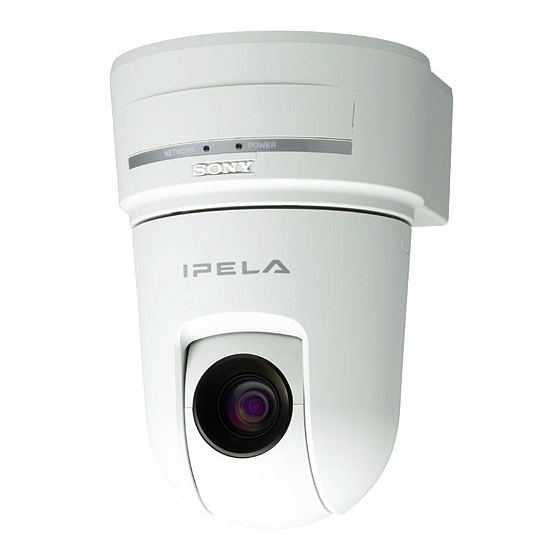
- Page 7 Sony SNC-RX550N/W-MT Camera mounted on Pole............1-3 Figure 1-2 All Components in Boxes ....................1-4 Figure 1-3 Motorola WMC6300 and the WMC7300 Wireless Modem Card ........1-5 Figure 1-4 Sony SNC-RX550N/W-MT Camera and PCMCIA Slot Location........1-6 Figure 1-5 Sony SNC-RX550N/W-MT Camera Interface Connection View ........1-7 Figure 1-6 Correct and Incorrect Method of WMC Insertion into Camera ...........1-8...
- Page 8 List of Figures Figure A-4 IP Address and Firmware Version Verification Screen..........A-2 Figure A-5 Begin Upgrade Screen ....................A-3 Figure A-6 Firmware Upgrade Progress Screen................A-3 Figure A-7 Firmware Successfully Upgraded Screen ...............A-4 Figure A-8 Local Area Connection Properties Screen ..............A-5 Figure A-9 Selecting TCP/IP from the Local Area Connection Properties Screen......A-5 Figure A-10 IP Address and Subnet Mask Settings ................A-6...
- Page 9 List Tables List of Tables ..........Table 1-1 WMC MAC Address Record ....................1-6 Table 2-1...
- Page 10 List of Tables This page intentionally left blank. 6881011Y68-B October 2006...
- Page 11 List Procedures List of Procedures ..........Procedure 2-1 Configuration Using a Laptop ..................2-1 Procedure 2-2...
- Page 12 List of Procedures This page intentionally left blank. 6881011Y68-B October 2006...
-
Page 13: Chapter 1: Overview
Due to the fact that the Mesh Camera System product kits utilize several components to be setup and configured, this Guide will focus on the setup and configuration of the Motorola MOTOMESH WMC7300 wireless cards for use with the Sony SNC-RX550N-MT camera. Detailed dome housing and hardware assembly information, as well other Camera Setup information will be referred to the specific manufacturer’s document(s). -
Page 14: About The Products
..........The Motorola Wireless Mesh Broadband camera kits are packaged solutions for wireless data users interested in wireless broadband video capabilities. -
Page 15: Motomesh Wmc6300 Sony Camera Kit
MOTOMESH 1.2 Mesh Camera System Setup and Configuration Guide MOTOMESH WMC6300 SONY CAMERA KIT* • 1 Sony SNC-RX550N/W-MT • 1 WMC6300 Cards • 1 Outdoor dome, antenna, and mount WMB (MEA) WMC6300 SONY CAMERA KIT* • 1 Sony SNC-RX550N/W-MT •... -
Page 16: Overview Of Mesh Camera System Setup And Installation
3. Install Sony Camera into Dome Housing (Use hardcopy of Indoor and Outdoor Dome Housing or PDF) 4. Install Camera assembly into final location (Use this Guide) 5. Manage Camera using Motorola MeshManager and Sony RealShot Manager (Use this Guide, RealShot Users Guide, and Sony Network SNCRX550 Camera Users Guide) Device Assembly Components . -
Page 17: Device Assembly Sequence
Device Assembly Sequence The Device Assembly can be broken down into three main parts, Part I - Pre-Configuration, Part II - Indoor Assembly, and Part III - Outdoor Installation, prior to configuring the Motorola WMC7300 wireless card for the MOTOMESH network. -
Page 18: Figure 1-4 Sony Snc-Rx550N/W-Mt Camera And Pcmcia Slot Location
Chapter 1: Overview Table 1-1 WMC MAC Address Record Type of card WMC MAC Address Device Name or location (6300 or 7300) (Optional) 4. If possible, test the camera in the pre-configuration stage Figure 1-4 Sony SNC-RX550N/W-MT Camera and PCMCIA Slot Location The PCMCIA slot is located behind removable cover. -
Page 19: Figure 1-5 Sony Snc-Rx550N/W-Mt Camera Interface Connection View
MOTOMESH 1.2 Mesh Camera System Setup and Configuration Guide Figure 1-5 Sony SNC-RX550N/W-MT Camera Interface Connection View 6881011Y68-B October 2006... -
Page 20: Correct Motorola Wireless Modem Card Insertion Technique
Chapter 1: Overview Correct Motorola Wireless Modem Card Insertion Technique To properly insert a WMC7300 Card into a Sony RX5500N/W-MT camera that is resting on a hard surface (as shown in graphic “A” below); hold the WMC card with the color label facing DOWN (the MAC Address label will be facing UP). -
Page 21: Figure 1-7 Plate Locations For Mounting The Camera
MOTOMESH 1.2 Mesh Camera System Setup and Configuration Guide Figure 1-7 Plate locations for Mounting the Camera Red Circle indicates correct Camera plate mounting location Figure 1-8 Example of Camera Correctly Mounted to Plate C.) Attach the removed plate into the camera base. -
Page 22: Figure 1-9 Dome Housing Component For The Sony Snc-Rx550N/W-Mt Camera
Chapter 1: Overview D.) Prior to installing the camera into the housing, attach the power and alarm cables per instructions. E.) Line up the plate you have installed on the camera with the correct holes in the housing. Attach the camera to the housing. Figure 1-9 Dome Housing Component for the Sony SNC-RX550N/W-MT Camera F.) Place the safety line on the housing to the dome cover. -
Page 23: Figure 1-10 Gooseneck Component Out Of The Box
20 to 12 AWG stranded wire. Tap A is the 24VAC and is the one to use. The chart also shows AWG vs. distance. Motorola CAN NOT recommend a specific wire configuration due to the fact that the wire must be cut to length based on the termination/connection to the local power source at a specific site, and that the installation must comply with local building codes. -
Page 24: Part Iii - Outdoor Installation
Chapter 1: Overview TIP FROM THE FIELD: You will need to manually wire (setup) the power supply to support BOTH the camera (yellow and orange wire) AND the Heater/Blower (green and blue wire). A total of four lines will need to be powered up on the connector. 4. -
Page 25: Figure 1-14 Pole Mounting The Dome Camera
MOTOMESH 1.2 Mesh Camera System Setup and Configuration Guide B.) Attach the assembly to the pole using stainless steel straps. C.) Remove coupling from the housing and attach to the gooseneck wall mount. D.) Follow camera mounting procedure to mount onto the dome, located in the Outdoor and Indoor Dome Housings hard copy or in PDF file (Dome Housing Installation.pdf). -
Page 26: Figure 1-15 Example Of Gooseneck Component Setup In The Field
Chapter 1: Overview Figure 1-15 Example of Gooseneck Component Setup in the Field 4. Connect the AC power source to the power supply (hardwire). TIP FROM THE FIELD: Listen for the camera PTZ motor to activate. You will hear the camera spin to its 'Home' location (zero degrees). -
Page 27: Visual Examples Of Mesh Camera System Deployed In The Field
MOTOMESH 1.2 Mesh Camera System Setup and Configuration Guide Visual Examples of Mesh Camera System Deployed in the Field Figure 1-17 Example of Mesh Camera System Setup in the Field (1) Figure 1-18 Example of Mesh Camera System Setup in the Field (2) -
Page 28: Device Deployment Rf Guidelines
Chapter 1: Overview Device Deployment RF Guidelines Observe the following guidelines when deploying fixed Mesh Networking devices: • The camera may be mounted on a pole having a diameter of 1-3.5 inches, utilizing the provided bracket. • The antenna must have a separation distance of at least 2 meters from the body of all persons and must not be co-located or operating in conjunction with any other antenna or transmitter. -
Page 29: Chapter 2: Configuration
..........This chapter describes how to configure the Sony Camera for use with the Motorola MOTOMESH MeshManager Application Suite. -
Page 30: Figure 2-1 Selecting Internet Protocol (Tcp/Ip)
Chapter 2: Configuration Select the Internet Protocol (TCP/IP) selection. Figure 2-1 Selecting Internet Protocol (TCP/IP) 6881011Y68-B October 2006... -
Page 31: Figure 2-2 Selecting The Properties Button
MOTOMESH 1.2 Mesh Camera System Setup and Configuration Guide Select the Properties button Figure 2-2 Selecting the Properties Button 6881011Y68-B October 2006... -
Page 32: Figure 2-3 Entering Tcp/Ip Properties
Chapter 2: Configuration Select Use the following IP address radio button. Figure 2-3 Entering TCP/IP Properties Populate the IP address field with 192.168.0.150. Populate the Subnet mask field with 255.255.255.0. Click on OK for the changes to take affect. Close all Local Area Connection properties windows. Insert the MEA/MOTOMESH WMC6300/7300 wireless card into the camera’s PCMCIA slot 6881011Y68-B October 2006... -
Page 33: Figure 2-4 Verifying Connectivity To The Camera
MOTOMESH 1.2 Mesh Camera System Setup and Configuration Guide Point a browser to the camera’s default IP address or 192.168.0.100 to verify connectivity. Figure 2-4 Verifying Connectivity to the Camera 6881011Y68-B October 2006... -
Page 34: Figure 2-5 Camera Web Interface Showing The Mesh Network Button
Chapter 2: Configuration After connectivity is confirmed, set the options for the Wireless Card in one of two ways: 1.) From the camera home webpage, select the Setting button | Network tab | Wireless tab | Mesh Network button. Selecting this button will provide access to the Mesh wireless card web interface. Please note that this option will ONLY work when a MEA card is installed. -
Page 35: Configuring The Camera's Host Ip Address To Dhcp In Motomesh Meshmanager
Configuring the Camera’s Host IP Address to DHCP in MOTOMESH MeshManager The procedure below describes how to configure the Sony camera in the Motorola MOTOMESH Device Manager environment. The IP Setup Program that is referred to in the Sony RealShot Manager Guide does not work in the Motorola MOTOMESH network environment. -
Page 36: Figure 2-7 Selecting The Camera Device In Motomesh Meshmanager
Chapter 2: Configuration After the camera device has been added to Device Manager, double-click on the camera device. Figure 2-7 Selecting the Camera Device in MOTOMESH MeshManager Select the Configuration option form the Action drop down list. Figure 2-8 Selecting the Configuration Option 6881011Y68-B October 2006... -
Page 37: Figure 2-9 Selecting The Ip Addressing Tab
MOTOMESH 1.2 Mesh Camera System Setup and Configuration Guide From the Configuration window, select the IP Addressing tab. Figure 2-9 Selecting the IP Addressing tab 6881011Y68-B October 2006... -
Page 38: Figure 2-10 Selecting The Network Dhcp Option
Chapter 2: Configuration From within the IP Addressing tab, ensure that under the HOST heading, the Host Network DHCP Enabled option is set to TRUE. Note that the IP Addresses shown in the Host Fixed IP address are automatically generated at the initial device setup time and do NOT reflect the TRUE Host IP Address shown. -
Page 39: Figure 2-12 Wireless Card Web Interface
MOTOMESH 1.2 Mesh Camera System Setup and Configuration Guide 2.) Redirect the browser to http://192.168.0.100/en/l4/network/meshnetwork.html. (This is the wireless card configuration web interface). Figure 2-12 Wireless Card Web Interface Select the Network DHCP radio button in the Addressing scheme selection field. -
Page 40: Statically Provisioning The Camera's Host Ip Address In Meshmanager
Chapter 2: Configuration Statically Provisioning the Camera’s Host IP Address in MeshManager Procedure 2-4 Statically Provisioning the Camera’s Host IP Address in MeshManager Provision the MOTOMESH card. (Refer to the MeshManager User’s Guide for details). After the camera device has been added to Device Manager, double-click on the camera device. Figure 2-13 Selecting the Camera Device in MOTOMESH MeshManager 6881011Y68-B October 2006... -
Page 41: Figure 2-14 Selecting The Configuration Option
MOTOMESH 1.2 Mesh Camera System Setup and Configuration Guide Select the Configuration option form the Action drop down list. Figure 2-14 Selecting the Configuration Option From the Configuration window, select the IP Addressing tab. Figure 2-15 Selecting the IP Addressing tab... -
Page 42: Figure 2-16 Selecting The Network Dhcp Option
Chapter 2: Configuration From within the IP Addressing tab, ensure that under the HOST heading, the Host Network DHCP Enabled option is set to FALSE. Set the Host Fixed IP address to an IP address in the same subnet (10.3.X.X for 2.4 or 10.4.X.X for 4.9) and outside the DCHP lease range (default: 10.3.0.100 to 10.3.254.254 for 2.4 or 10.4.0.100 to 10.4.254.254 for 4.9) The static range default is 10.3.0.2-99 or 10.4.0.2-99. -
Page 43: Statically Provisioning The Camera's Host Ip Address From The Wired Side Of The Camera
MOTOMESH 1.2 Mesh Camera System Setup and Configuration Guide Statically Provisioning the Camera’s Host IP Address from the Wired Side of the Camera IMPORTANT: The IP address used in the Camera’s web page and in MeshManager must match. Procedure 2-5 Configuring the Camera’s Host IP Address to DHCP... -
Page 44: Determining Camera Host Ip Address
RealShot Manager application and where to find the Launch Web Browser feature in MeshManager. Please note that the directions listed in the following procedure will only apply when used with the correct version of Motorola MeshManager software. 6881011Y68-B October 2006... -
Page 45: Ip Addressing Considerations And The Wmc6300/7300 Card
MOTOMESH 1.2 Mesh Camera System Setup and Configuration Guide Procedure 2-6 Determining Camera Host IP Address To find the IP Host Address, right-click on the Camera device in the MeshManager Device Tree, and select Current IP Address from the popup menu. -
Page 47: Chapter 3: Support And Repair Information
Motorola System Support Center (SSC). When you consult the Motorola SSC, you increase the likelihood that problems are rectified in a timely fashion and that warranty requirements are satisfied. Check your contract for specific warranty and service information. - Page 48 Chapter 3: Support and Repair Information This page intentionally left blank. 6881011Y68-B October 2006...
-
Page 49: (Appendix A) Upgrade Process For The Sony Camera Firmware
Appendix A: Reference Information ..........(Appendix A) Upgrade Process for the Sony Camera Firmware . -
Page 50: Figure A-2 Eula For The Snc-Rx550 Upgrade
Appendix A: Reference Information Select the Agree option to accept the EULA (End User License Agreement) and select the Next button. Figure A-2 EULA for the SNC-RX550 Upgrade Enter the IP address of the camera, as well as the Administrator Name and Administrator Password, and then click on the Next button. -
Page 51: Figure A-5 Begin Upgrade Screen
MOTOMESH 1.2 Mesh Camera System Setup and Configuration Guide Click on OK to begin the upgrade process. Figure A-5 Begin Upgrade Screen This screen shows the progress indicator for the upgrade process. Figure A-6 Firmware Upgrade Progress Screen 6881011Y68-B October 2006... -
Page 52: (Appendix A) Mea/Motomesh - Sony Camera Quick Network Configuration Check Guide
Appendix A: Reference Information Select the Finish button to complete the upgrade task. Figure A-7 Firmware Successfully Upgraded Screen End of Procedure. (Appendix A) MEA/MOTOMESH – Sony Camera Quick Network Configuration Check Guide ..........Testing the Functionality of a MEA Enabled Camera in an Infrastructure Environment This portion of the MEA/MOTOMESH –... -
Page 53: Testing The Functionality Of A Mea Enabled Camera In A Peer-To-Peer Environment
MOTOMESH 1.2 Mesh Camera System Setup and Configuration Guide Point a web browser to the IP address of the host (camera). When the camera’s web page is displayed, click on ENTER and verify the camera is transmitting images. End of Procedure. -
Page 54: Figure A-10 Ip Address And Subnet Mask Settings
Appendix A: Reference Information Click the Use the following IP address radio button and populate the IP address field with 192.168.0.150. Populate the Subnet mask field with 255.255.255.0. Click on OK for the changes to take affect. Close all Local Area Connection Properties windows. These steps allow the laptop to communicate with the camera to determine IP address of the wireless interface. -
Page 55: Figure A-11 Sony Camera Local Web Page
MOTOMESH 1.2 Mesh Camera System Setup and Configuration Guide Point a browser to the camera’s default IP address or 192.168.0.100 to verify connectivity. Figure A-11 Sony Camera Local Web Page At the Sony Web page, click on the Setting button area. If you are presented with a Login dialog, use lowercase admin for both, username and password. - Page 56 Appendix A: Reference Information to Force Authorized. Note down the IP address listed on the page, as you will need it for the next step. Disconnect the cross-over Ethernet cable and point a browser to the IP address as noted above. This will verify functionality and connectivity of the wireless link End of Procedure.
- Page 57 Index Index ..........IP address field, 2-4 IP Addressing, 2-9, 2-10, 2-13, 2-14, 2-17 antenna, 1-16...
- Page 58 Index TCP/IP, 2-2 wireless card, 2-4, 2-6, 2-10, 2-15 TCP/IP Properties, 2-4 WMC6300, 2-4, A-1 Trademarks, iii WMC7300, 1-1, 1-5, 2-4, 2-17, A-1 Verifying Connectivity, 2-5 6881011Y68-B October 2006 Index...
- Page 59 MiSC – Mobile Internet Switching Controller PTZ – Pan/Tilt/Zoom (feature and motor on Sony Camera) WMB – Wireless Mobile Broadband also referred to as MEA WMC – Motorola Wireless Modem Card, can apply to WMC6300 or WMC7300 model number WR – Wireless Router...
- Page 60 Glossary This page intentionally left blank. 6881011Y68-B October 2006 Glossary-2...