Table of Contents
No. 263
EGF
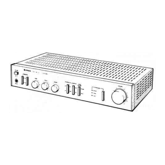
HA-2800
HA-1800
CONTENTS
SPEC|F|CAT|ONS..
..'.....'..1
FEATURES..
.......3
DESCRIPTION
OF
THE NEW CIRCUIT.....3
BLOCK
DIAGRAM
,..,..4
PRINTED
WIRING
BOARD
......"."5
crRcutT
DTAGRAM
........6
RPTNTED
WtRtNG
BOARD
.....'........'..'.7
CIRCUIT
DIAGRAM
.....".."8
DISASSEMBLY
AND REPLACEMENT.......9
REPLACEMENT PARTS LIST...."'10,11,12,13
FRONT
AND
REAR PANEL
.................14
SAIETY PRECAUTION
SPECIFICATIONS
Power
output
(Both
channels
driven)
Power
bandwidth
Frequency characteristics
TUNER.
AUX (HA.I
8OO).
TAPE
PHONO
Harmonic
distùrtion (8
ohnrs)
(at
rated
output)
(at
I
/l
rated
output)
lnlernrodulation distortion
(at
I
/2
rated
output)
lnpuî
sensitivity/lmpedanee
PHONO
TUNER,
AUX(HA-r800)
TAPE
PLAY
25
watts*
per channel,
min.
RMS,
at
8
ohms
from
40
Hz
to
20
kHz,
with
no
more than O.l%
toîal
harmonic
distortion.
15
W/ch +
l5
W/ch
(4/8
ohms.
I
kHz.
T H.D..0
l%)
l0
Hz
-30
kHz
(8
ohrns.
T
H.D
0.1%
l/l
Rated)
l0
Hz
-
40 kHz
(+l
0.-30
dB)
RIAA
t
0.5 dB
Less
than
0
l%
kss
than
0.1%
kss
than
0.1%
1.5
mVi47
k-ohms
150
nrV/40
k-ohms
150
mV/40
k-ohms
Output
level
TAPE
REC
OUT
Phono overload level
(at
I
kHz
)
Signal-to-noise
ratio
(lHF,
A network)
PHONO
TUNER,
AUX (HA-I
8OO).
TAPE
Damping lactor
Bass
control
Treble
control
L.oudhess
control
Subsonic
fìlter
Power supply
Power
consumption
Dmensions
Weight
150
mV
ll0
mV
7l
dB
93 dB
20
(l
kHz"
8
ohms)
t8dB(l00Hz)
t8dB(l0kHz)
+6dB(l00Hz)
+ 4
dB
(10
kHz)
l0
Hz
AC
I
20
V 60
Hz,
-
210
V
50/60
Hz
-
240V
50/ó0
Hz
or
-
I
20
V/ll0
v
1240
V
5o160 Hz
90
W
(at l/10
rated
ourput)
140 W
(at
I
/3
rated
ourput)
210
W
(at
rated
out!ut)
435 (W)
x
83
(H)
x
243
(D)
mm
4 8
kg
(HA-2800)
4.6
kg
(HA-l
800)
tMeasured pursuant
to
the
Federal Trade
Commission's Trade Regulation
Rule on
Power
Output
Claims
for Amplifiers.
The following precautions should be observed when servicing
1.
Since
many
parts
in
the unit have
special
safety related characteristics,
always
use genuine Hitachi's replacement
parts
Especially
critical parts
in
the power circuit block should not
be
replaced with other makers.
Critical parts are marked
with
A
in
the schematic diagram and circuit board
diagram.
2.
Before returning a repaired
unit
to the customer, the service technician
must
thoroughly test the
unit
to
ascertain that
it
is completely
safe
to
operate without danger of electrical
shock
SPECIFICATIONS
AND
PARTS
ARE
SUBJECT
TO
CHANGE FOR
IMPROVEMENT.
STEREO AMPLIFIER
May
1981
TOYOKAWA
WORKS
Table of Contents


