Table of Contents
Table of Contents
Troubleshooting

Related Manuals for HP 3300A


Summary of Contents for HP 3300A
- Page 1 TM 11-6625-2495-14&P TECHNICAL MANUAL OPERATOR’S, ORGANIZATIONAL, DIRECT SUPPORT, AND GENERAL SUPPORT MAINTENANCE MANUAL (INCLUDING REPAIR PARTS AND SPECIAL TOOLS LISTS) GENERATOR, SIGNAL SG-747/U (HEWLETT-PACKARD 3300A) (NSN 6625-00-118-6736) HEADQUARTERS, DEPARTMENT OF THE ARMY 4 AUGUST 1980...
- Page 2 SAFETY STEPS TO FOLLOW IF SOMEONE IS THE VICTIM OF ELECTRICAL SHOCK DO NOT TRY TO PULL OR GRAB THE INDIVIDUAL IF POSSIBLE, TURN OFF THE ELECTRICAL POWER IF YOU CANNOT TURN OFF THE ELECTRICAL POWER, PULL, PUSH, OR LIFT THE PERSON TO SAFETY USING A DRY WOODEN POLE OR A DRY ROPE OR SOME OTHER INSULATING MATERIAL SEND FOR HELP AS SOON AS POSSIBLE...
- Page 3 TM 11-6625-2495-14&P WARNING Adequate ventilation should provided while using TRICHLOROTRIFLUOROETHANE. Prolonged breathing of vapor should be avoided. The solvent should not be used near heat or open flame; the products of decomposition are toxic and irritating. Since TRICHLOROTRIFLUOROETHANE dissolves natural oils, prolonged contact with skin should be avoided. When necessary, use gloves which the solvent cannot penetrate.
- Page 4 OPERATOR’S, ORGANIZATIONAL, DIRECT SUPPORT, AND GENERAL SUPPORT MAINTENANCE MANUAL, (INCLUDING REPAIR PARTS AND SPECIAL TOOLS LISTS) GENERATOR, SIGNAL SG-747/U (HEWLETT-PACKARD 3300A) (NSN 6625-00-118-6736) REPORTING OF ERRORS You can improve this manual by recommending improvements using DA Form 2028-2 located in the back of the manual. Simply tear out the self-addressed form, fill it out as shown on the sample, fold it where shown, and drop it in the mail.
-
Page 5: Table Of Contents
TM 11-6625-2495-14&P TABLE OF CONTENTS (Continued) Section Page Section Page GENERAL INFORMATION ......1-1 MAINTENANCE (Cont’d) 1-1. General.......... 1-1 5-13. Maximum Output Level, 1-5. Electronic Frequency Control ..1-1 Loaded........5-1 1-7. Output System....... 1-1 5-16. Square Wave Response ....5-2 1-9. - Page 6 Controls and Connectors....... 3-0 5-9. Normal Oscillator Wave Forms ....5-10 4-1. Block Diagram ..........4-1 6-1. 3300A Top and Bottom Views ....6-2 5-1. 600 ohm or 50 ohm Load Output Test 6-2. Oscillator Circuit Schematic (A11, A13 Setup ............. 5-2 and A14)..........
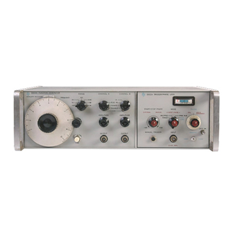
- Page 7 SECTION 0 INTRODUCTION 0-1. SCOPE. This manual describes Generator, Signal SG-747/U (HP-3300A) (fig. 1-1) and provides maintenance instructions. Throughout this manual, SG-747/U is referred to as the Hewlett-Packard HP-3300A Function Generator. 0-2. INDEXES OF PUBLICATIONS. DA Pam 310-4. Refer to the latest issue of DA Pam 310-4 to determine whether there are new editions, changes, or additional publications pertaining to the equipment.
- Page 8 TM 11-6625-2494-14&P Figure 1-1. Model 3300A Function Generator Table 1-1. Specifications AVAILABLE PLUG-IN UNITS: SINE WAVE DISTORTION: <1%. 0.01 Hz to 10 Model 3301A Auxiliary Plug-In. kHz; <3%, 10 kHz to 100kHz on the X10K range. Model 3302A Trigger Plug-In.
-
Page 9: General Information
Separate connectors on the rear panel provide 1-3. The -hp- Model 3300A Function Generator is a terminals for circuit ground ( ), output ground ( type of relaxation oscillator. -
Page 10: Installation
5" Rack Mount Kit (-hp- Part No. 5060-0775). for repackaging for shipment. Instructions for the conversion are included with the kit. The rack mount for the Model 3300A is a standard width 2-3. INITIAL INSPECTION. of 19 inches. -
Page 11: Description Of Front And Rear Panel Controls And Connectors
Section II Model 3300A 115V/230V Slide Switch: S2 makes proper CHANNEL B Function Switch: S5, a five position connections in primary of input transformer for rotary switch which selects the desired OUTPUT selected input line voltage. (11). Power Input Jack: J1, male receptacle for input AMPLITUDE Controls: R12 and R9 attenuators power cable. -
Page 12: Operating Instructions
To control the frequency of the Model 3300A 3-4. Each operating control and connector located on externally (remotely) proceed as follows: the 3300A is identified and described in Figure 3-1. The description of each component is keyed to an illustration Remove FREQ DIAL-to-FREQ CONTROL of that component. - Page 13 Section III Model 3300A ± 25 V, between CKT GND and the dc may be applied between this common common grounds. OUTPUT GND, SHIELD ground and PWR LINE GND. GND, and PWR LINE GND should be shorted together (15). WARNING WHEN THE OUTPUT GROUND IS If more than ±...
-
Page 14: Theory Of Operation
4-1. INTRODUCTION. comparator multivibrator again changes state thus completing the cycle. 4-2. This section contains a description of the theory of operation of the -hp- Model 3300A Function Generator 4-7. frequency control network, governed with the -hp- Model 3301A Auxiliary Plug-in. -
Page 15: Schematic Theory
Section IV Model 3300A R45 provide a low resistive path to ensure rapid rise and 4-10. sync pulse produced by an fall time of the square wave in the event the capacitance differentiating network. The negative pulse at the output of the load is high. -
Page 16: Power Supply
Model 3300A Section IV 4-27. POWER SUPPLY (Figure 6-5). combination. When this forward bias increases to a level sufficient to allow the diodes to conduct, any increase in the collector current of Q4 will pass through the diodes 4-28. The power supply consists of two full wave and not enter the base of Q2. - Page 17 Adjustment and Counter with 5262A Plug- Calibration in Time Interval Unit Distortion Analyzer Range: 10 Hz to 100kHz Performance Checks -hp- Model 331A Distortion Freq. Accuracy: +2% Analyzer Sensitivity: 0.3%fullscale Input: 1 volt rms Oscilloscope Sensitivity: 50 mV/cm Performance Checks,...
-
Page 18: Maintenance
INTRODUCTION. Distortion should be less than 3%. 5-2. This section contains information necessary for NOTE the proper maintenance of the -hp- Model 3300A Function Generator. The required test equipment is The sine function is electronically listed in Table 5-1. Test equipment with comparable... -
Page 19: Square Wave Response
Test equipment required: DC Power Supply Connect CHANNEL A OUTPUT without a (-hp- Model 723A) and Oscilloscope (-hp- load to the oscilloscope using the 10:1 Model 175A/1750B). Probe, and set the 3300A controls as follows: CAUTION CHANNEL A function ....SQUARE VOLTAGE APPLIED TO FREQUENCY FREQUENCY dial ......10... -
Page 20: Power Supply Adjustments
NOTE When it is necessary to repair or adjust the Model This voltage will vary with oven 3300A, one or more covers will have to be removed. To amplifier transistors. remove either the top or bottom cover, remove the two Turn 3300A off for approximately 1 minute, phillips screws and slide the cover to the rear. -
Page 21: Voltage Monitoring Points Top And Bottom
Section V Model 3300A Figure 5-3. Adjustment Point Location Figure 5-4. Voltage Monitoring Points Top and Bottom... -
Page 22: Current Source Adjust
Loosen dial from hub and adjust the and then again with the dial set to 10. The frequency of 3300A to exactly 100 cps by symmetry error at both dial settings should rotating the hub. Set the dial to read "1"... -
Page 23: Distortion Adjust
OUTPUT 5-44. SERVICING ETCHED CIRCUIT BOARDS. distortion analyzer and set Model 3300A 5-45. The Model 3300A has six etched circuit boards. controls as follows: Use caution when removing them to avoid damaging FREQUENCY dial ......1 mounted components. The -hp- Part No. -
Page 24: Servicing Rotary Switches
5-55. A malfunction isolating tool can be fabricated for isolating a malfunction to the 3300A or the plug-in unit. A of the capacitors in the feedback circuit of the Triangle 50 pin connector -hp- Part No. 1251-0099 can be fitted... -
Page 25: Precautions
Section V Model 3300A jumper location). If 3300A operation is normal with this diameter redwire (22 gage) should be left connected to plug mated with J6, the trouble is in the plug-in unit. XA12 Pin 1. When the -20 volt power supply is left out, the oven remains in full heat condition. -
Page 26: Troubleshooting Tree
Model 3300A Section V Table 5-4. Troubleshooting Aid (Cont'd) SYMPTOM POSSIBLE CAUSE Half of sine wave clipped on both channels. Check A14Q5 and A14Q7. The synthesizer waveform is symmetrical about 10 volts at the base of A14Q5 and at the corresponding junctions along the voltage divider R10 to R15 and R25 to R20. -
Page 27: Troubleshooting Tables
Symptoms and possible causes are listed. Table 5-5, Maintenance Correlation Table, lists various 3300A functions and gives the corresponding performance checks and adjustments. Figure 5-9. Normal Oscillator Wave Forms Table 5-5. Maintenance Correlation Table... -
Page 28: Factory Selected Components
Model 3300A Section V Table 5-5. Maintenance Correlation Table (Cont’d) ADJUSTMENT AND FUNCTION PERFORMANCE CHECK CALIBRATION TROUBLESHOOTING DC Output None Paragraph 5-39 and 5-40 Change A15 or A16 Q1 and/or Q2, if all functions negative increase value of R10* not to exceed 3K... - Page 29 PERFORMANCE CHECK TEST CARD Hewlett-Packard Model 3300A Test Performed by ______________________________ Function Generator Date ______________________________ Serial No. __________ CHECK DESCRIPTION SPECIFICATION INDICATION 1. Dial Accuracy 1 x .01 between 90.9 and 111.1 sec _______ 10 x .01 between 9.90 and 10.1 sec _______ 1 x .1...
-
Page 30: Circuit Diagrams
The schematic diagrams are laid out to facilitate ease of following signal flow developing 6-6. Figure 6-6 shows the connections brought out understanding of the detailed theory of operation. from the main frame of the 3300A for use with plug-in Etched circuit board integrity is maintained whenever units. possible. - Page 31 Model 3300A Section VI Figure 6-1. 3300A Top and Bottom Views.
-
Page 32: Oscillator Circuit Schematic (A11, A13 And A14)
Model 3300A Section VI Figure 6-2. Oscillator Circuit Schematic (A11, A13 and A14). -
Page 33: Output Amplifiers Schematic (A15 And A16)
Model 3300A Section VI Figure 6-4. Output Amplifiers Schematic (A15 and A16). 6-5/6-6... - Page 34 TM 11-6625-2495-14&P THIS PAGE CURRENTLY NOT AVAILABLE FOR DIGITIZATION PAGE # Figure 6-3.
- Page 35 Model 3300A Section VI Figure 6-5. Power Supply Schematic (A12 and A11). 6-7/6-8...
- Page 36 Model 3300A Section VI Figure 6-6. J6 Plug-In Receptacle.
- Page 37 Model 3300A Section VII INDEX DESCRIPTION QUANTITY PART NO. ASSEMBLY: FRAME 5 x 11 F.M. 5060-0731 PANEL: FRONT 03300-00201 PANEL: REAR 03300-00203* COVER: REAR SIDE 5000-0732 COVER: FRONT SIDE 5000-0733 COVER: TOP ASSEMBLY 5060-0739 COVER: BOTTOM ASSEMBLY 5060-0751 HANDLE: SIDE ASSEMBLY...
-
Page 38: Replaceable Parts
7-5. To obtain replacement parts, address order or order of their reference designators and indicates the description, -hp- part number of each part, together with inquiry to your local Hewlett-Packard Field Office. (See any applicable notes, and provides the following: field office location list). -
Page 39: Replaceable Parts
Model 3300A Section VII Table 7-1. Replaceable Parts REFERENCE -hp- DESIGNATOR PART NO DESCRIPTION MFR. MFR. PART NO. A1 thru A6 Used in instruments serial prefixed 519-, 533-, 609-, 616- and 622-. See Supplement B for replaceable parts. A7 thru A10... - Page 40 Model 3300A Section VII Table 7-1. Replaceable Parts (Cont’d) REFERENCE -hp- DESIGNATOR PART NO DESCRIPTION MFR. MFR. PART NO. A12Q3, A12Q4 1854-0087 TSTR: Si NPN -hp- A12Q5 1854-0039 TSTR: Si NPN 2N3053 86684 2N3053 A12Q6 1854-0087 TSTR: Si NPN -hp-...
- Page 41 Model 3300A Section VII Table 7-1. Replaceable Parts (Cont’d) REFERENCE -hp- DESIGNATOR PART NO DESCRIPTION MFR. MFR. PART NO. A13CR1 1901-0025 Diode: Si 100 mA at 1V 100 piv 12 pF 07263 FD 2387 A13L1 9170-0016 Bead: ferrite 02114 56-590-65/3B...
- Page 42 Model 3300A Section VII Table 7-1. Replaceable Parts (Cont’d) REFERENCE -hp- DESIGNATOR PART NO DESCRIPTION MFR. MFR. PART NO. A14Q1, A14Q2 1854-0071 TSTR: Si NPN 2N3391 04713 MPA. 3391 A14Q3, A14Q4 1853-0010 TSTR: Si PNP** -hp- A14Q5, A14Q6 1854-0071 TSTR: Si NPN 2N3391 04713 MPA.
- Page 43 Model 3300A Section VII Table 7-1. Replaceable Parts (Cont’d) REFERENCE -hp- DESIGNATOR PART NO DESCRIPTION MFR. MFR. PART NO. R: fxd prec met flm 511Ω ±1% 1/8 W A14R52 0757-0416 19701 MF5C T-O R: fxd comp 1K ±5% 1/4 W...
- Page 44 Model 3300A Section VII Table 7-1. Replaceable Parts (Cont’d) REFERENCE -hp- DESIGNATOR PART NO DESCRIPTION MFR. MFR. PART NO. Chassis Mounted Components Not Assigned Î 0150-0012 C: fxd disc cer durez coated 0. 01 56289 29CZ14A3 ±20% 1000 vdcw Î...
- Page 45 Model 3300A Section VII Table 7-1. Replaceable Parts (Cont’d) REFERENCE -hp- DESIGNATOR PART NO DESCRIPTION MFR. MFR. PART NO. Miscellaneous (Cont’d) 03300-00608 Cover: chassis top inner shield -hp- 03300-46904 Cover: oven -hp- 03300-00606 Cover: rear panel protection plate -hp- 03300-01203...
- Page 46 TM 11-6625-2495-14&P Table 7-2. PART NUMBER - NATIONAL STOCK NUMBER CROSS REFERENCE INDEX NATIONAL NATIONAL PART STOCK PART STOCK NUMBER FSCM NUMBER NUMBER FSCM NUMBER 87034 6240-00-951-3376 RDM15F201J3C 00853 5910-00-852-2656 CB1005 01121 5905-00-960-0099 RDM15F391J3C 00853 5910-00-914-4732 CB1015 01121 5905-00-102-5294 SS3723 04713 5961-00-442-9470 CB1025...
- Page 47 Model 3300A CODE LIST OF MANUFACTURERS The following code numbers are from the Federal Supply Code for Manufacturers Cataloging Handbooks H4-1 (Name to Code) and H4-2 (Code to Name) and their latest supplements. The date of revision and the date of the supplements used appear at the bottom of each page.
- Page 48 Model 3300A CODE LIST OF MANUFACTURERS (Continued) Code Code Code Manufacturer Address Manufacturer Address Manufacturer Address 24655 General Radio Co. West Concord, Mass. 71744 Chicago Miniature Lamp Works Chicago, Ill. 78947 Ucinite Co. Newtonville, Mass. 24681 Memcor Inc., Comp. Div.
- Page 49 Wayne, Ill. 91637 Dale Electronics, Inc. Columbus, Nebr. 95987 Weckesser Co. Chicago, Ill. THE FOLLOWING HP VENDORS HAVE NO NUMBER 91662 Elco Corp. Willow Grove, Pa. 96067 Microwave Assoc., West Inc. Sunnyvale, Calif. ASSIGNED IN THE LATEST SUPPLEMENT TO THE 91737 Gremar Mfg.
- Page 50 Model 3300A SALES & SERVICE OFFICES UNITED STATES ALABAMA CONNECTICUT LOUISIANA 1060 N. Kings Highway OHIO P.O. Box 22813 P.O. Box 4207 508 Tolland Street P.O. Box 856 Cherry Hill 08034 25575 Center Ridge Road 6300 Westpark Drive 2003 Byrd Spring Road S.W.
- Page 51 Model 3300A EUROPE AUSTRIA FRANCE Hewlett-Packard Vertriebs-GmbH NETHERLANDS Ataio Ingenieros SA TURKEY Unilabor GmbH Hewlett-Packard France Reginfriedstrasse 13 Hewlett-Packard Benelux, N.V. Enrique Larreta 12 Telekom Engineering Bureau Wissenschaftliche Instrumente Quartier de Courtaboeuf 8 Munchen 9 Weerderstein 117 Madrid, 16 P.O. Box 376 - Galata Rummelhardtgasse 6/3 Boite Postale No.
- Page 52 Model 3300A MANUAL BACKDATING CHANGES This manual backdating sheet makes this manual applicable to earlier instruments. Instrument- component values that differ from those in the manual, yet are not listed in the backdating sheet, should be replaced using the part number given in the manual.
-
Page 53: References
TM 11-6625-2495-14&P APPENDIX A REFERENCES DA Pam 310-4 Index of Technical Manuals, Technical Bulletins, Supply Manuals (Types 7, 8, and 9), Supply Bulletins and Lubrication Orders. DA Pam 310-7 Military Publications: US Army Equipment Index of Modification Work Orders. TB 43-180 Calibration Requirements for the Maintenance of Army Materiel. -
Page 54: Maintenance Allocation
TM 11-6625-2495-14&P APPENDIX D MAINTENANCE ALLOCATION SECTION I. INTRODUCTION h. Replace. The act of substituting a serviceable D-1. General like type part, subassembly, or module (component or This appendix provides a summary of the maintenance assembly) for an unserviceable counterpart. i. - Page 55 TM 11-6625-2495-14&P specifies, by the listing of a "work time" figure the particular code. appropriate subcolumn(s), lowest level maintenance authorized to perform the function listed in D-4. Tool and Test Equipment Requirements (Sec III) column 3. This figure represents the active time required to perform that maintenance function at the indicated a.
- Page 56 TM 11-6625-2495-14&P SECTION II. MAINTENANCE ALLOCATION CHART GENERATOR, SIGNAL SG-747/U (HP 3300A) MAINTENANCE CATEGORY TOOLS GROUP COMPONENT/ASSEMBLY MAINTENANCE NUMBER FUNCTION EQUIP. REMARKS Generator, Signal SG-747/U Inspect Test 1-4, 6, 7, Test 1-14 Adjust 1-5, 10, Calibrate Repair 15, 16 Overhaul...
- Page 57 H, D Capacitor 1 micro f 50V. H.P. 0160-0859 or equivalent H, D Variable Line Voltage Transformer CN-16/U 5950-00-235-2086 H, D D.C. Power Supply PP-6647/U (HP 723A) 6130-00-171-0801 H, D A.C. Voltmeter KE-459/U 6625-00-329-0457 H, D Printed Circuit Board Extender 15 Pin H.P.
- Page 58 SECTION IV. REMARKS REFERENCE REMARKS CODE Visuals Performance checks...
- Page 59 By Order of the Secretary of the Army: E. C. MEYER General, United States Army Chief of Staff Official: J. C. PENNINGTON Major General, United States Army The Adjutant General DISTRIBUTION: Active Army: WSMR (1) TSG (1) USAERDAA (1) USAARENBD (1) USAERDAW (1) USAINSCOM (2) Army Dep (1) except...
- Page 61 PIN: 046175-000...
- Page 62 This fine document... Was brought to you by me: Liberated Manuals -- free army and government manuals Why do I do it? I am tired of sleazy CD-ROM sellers, who take publicly available information, slap “watermarks” and other junk on it, and sell it. Those masters of search engine manipulation make sure that their sites that sell free information, come up first in search engines.