Siemens FT2010 Operation Manual
Floor repeater terminal
Hide thumbs
Also See for FT2010:
- Product data (302 pages) ,
- Operation manual (40 pages) ,
- Installation manual (12 pages)

Related Manuals for Siemens FT2010


Summary of Contents for Siemens FT2010
- Page 1 FT2010 Floor repeater terminal Operation Manual MP5 / IP5 Building Technologies 009310_i_en_-- 2013-11-14 Control Products and Systems...
- Page 2 Legal notice Technical specifications and availability subject to change without notice. © 2013 Copyright by Siemens Switzerland Ltd Transmittal, reproduction, dissemination and/or editing of this document as well as utilization of its contents and communication thereof to others without express authorization are prohibited.
-
Page 3: Table Of Contents
Table of contents About this document ..................5 Displays used in document ................7 Applicable documents ..................7 Download center....................8 Technical terms ....................8 History of changes ....................8 Safety ......................9 Safety instructions ....................9 Safety regulations for the method of operation ..........11 Standards and directives complied with ............13 2.3.1 CPR conformity and firmware version .......... - Page 4 Alarm verification concept (AVC) ..............28 Attendance check ................... 29 Investigation time.................... 29 Example of a verification process ..............29 Fire alarming ....................31 Faults / Troubleshooting ................33 Maintenance....................34 Building Technologies 009310_i_en_-- Fire Safety 2013-11-14...
-
Page 5: About This Document
1 About this document Goal and purpose This document describes the operation of the floor repeater terminal FT2010 in a fire detection system. The reader shall become familiar with the possible indications and operating functions on the terminal, as well as with the functionality of the terminal in the overall system. - Page 6 About this document Displays used in document Document identification The document ID is structured as follows: ID code Examples ID_ModificationIndex_Language_COUNTRY A6V10215123_a_de_DE -- = multilingual or international A6V10215123_a_en_-- A6V10315123_a_--_-- Date format The date format in the document corresponds to the recommendation of international standard ISO 8601 (format YYYY-MM-DD).
-
Page 7: Displays Used In Document
About this document Displays used in document 1.1 Displays used in document The form of display in the document sometimes uses tables. Deviations between the original and the table representation are shown below as examples: ABCDE FGHI 07:55:31 ABCD: 3 !ABCD: 421 ABC: 32 XXX YYY ZZZ... -
Page 8: Download Center
You can download various types of documents, such as data sheets, installation instructions, and license texts via the following Internet address: http://siemens.com/bt/download Enter the document ID in the 'Find by keywords' input box. You will also find information about search variants and links to mobile applications (apps) for various systems on the home page. -
Page 9: Safety
Safety Safety instructions 2 Safety 2.1 Safety instructions The safety notices must be observed in order to protect people and property. The safety notices in this document contain the following elements: Symbol for danger Signal word Nature and origin of the danger Consequences if the danger occurs Measures or prohibitions for danger avoidance Symbol for danger... - Page 10 Safety Safety instructions How risk of injury is presented Information about the risk of injury is shown as follows: WARNING Nature and origin of the danger Consequences if the danger occurs Measures / prohibitions for danger avoidance How possible damage to property is presented Information about possible damage to property is shown as follows: NOTICE Nature and origin of the danger...
-
Page 11: Safety Regulations For The Method Of Operation
2.2 Safety regulations for the method of operation National standards, regulations and legislation Siemens products are developed and produced in compliance with the relevant European and international safety standards. Should additional national or local safety standards or legislation concerning the planning, assembly, installation,... - Page 12 Disregard of the safety regulations Before they are delivered, Siemens products are tested to ensure they function correctly when used properly. Siemens disclaims all liability for damage or injuries caused by the incorrect application of the instructions or the disregard of danger warnings contained in the documentation.
-
Page 13: Standards And Directives Complied With
Safety Standards and directives complied with 2.3 Standards and directives complied with A list of the standards and directives complied with is available from your Siemens contact. 2.3.1 CPR conformity and firmware version In order to satisfy Ordinance No. 305/2011 (the Construction Products Regulation –... -
Page 14: Features
Features Maximum number of events that can be displayed 3 Features The floor repeater terminal is an indication and operation unit in a fire detection installation with the following functions: Indication of events 'ALARM' – 'Pre-ALARM' 'Fault' 'Isolation' 'Technical message' Operation 'Alarm delay off' 'Silence buzzer'... -
Page 15: Pmi
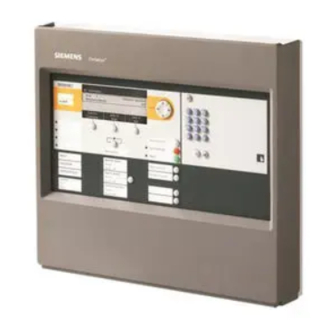
Maximum number of events that can be displayed 4 PMI The figure below shows the PMI of the floor repeater terminal. PMI of the floor repeater terminal 'ALARM' LEDs 'More alarms' button Display 'System On' LED Navigation buttons 'Remote alarm Active' LED 'Silence buzzer' button LEDs and function keys, configurable 'Acknowledge' button... -
Page 16: Buttons On The Pmi
Buttons on the PMI 4.1 Buttons on the PMI Navigation buttons The navigation buttons work in the same way as the arrow keys on a PC keyboard. With the buttons < > and < > it is possible to scroll to the next entry in a list.... -
Page 17: Display
Display 4.2 Display The display has two areas: ABCDE FGHI 07:55:31 ABCD: 3 ABCD: 421 ABC: 32 XXX YYY ZZZ ABCDEFGHI AAA/BBB ABCD: 026 ABC: 75 XXX YYY ZZZ ABCDE CCC Display representation with two indicated messages Header Representation area 4.3 Key switch You can use the 'Key switch' to release the operation. -
Page 18: Service Menu
Service menu 5 Service menu Various settings can be performed using a service menu. You can open the service menu using a combination of keys (see corresponding chapter). After calling up the menu and entering a password, the following menu items are available: 'Device information' –... -
Page 19: Operation
Operation ALARM Procedure 6 Operation 6.1 ALARM Procedure If your fire detection system has no delayed alarm transmission function ('AVC'), the variant –''Fire Brigade in' 'mm:ss' in Step 2 (see procedure to follow in the event of a fire) does not apply. ALARM operation sequence... -
Page 20
Operation ALARM Procedure Procedure in the event of alarm Action / Condition Consequence / Status Step
on the Person With 'AVC', countdown t2 for the examination of the Machine Interface 'ALARM' source starts Read top line on display –... -
Page 21: Switch Off Alarm Delay
Operation Switch off alarm delay 6.2 Switch off alarm delay An alarm delay in case of alarm is only possible if the fire detection installation is provided with 'AVC'. Alarm delay is a countdown until global alarming is initiated. In case of alarm, the alarm delay can be switched off. Global alarming is triggered immediately! Switching off the alarm delay Press. -
Page 22: Procedure In Case Of Fault
Operation Procedure in case of Fault 6.4 Procedure in case of Fault Step Actionon the Person Machine Interface Read message/fault location on the display on the Person Machine Interface Go to the fault location Eliminate the cause of the fault A list of possible 'Faults' and how they are eliminated can be found in the chapter 'Faults / Troubleshooting'. -
Page 23: Switching An Object On / Off
Operation Switching an object on / off 6.5 Switching an object on / off To avoid false alarms, you can switch off parts of a 'Site' in certain situations, e.g. for the purpose of maintenance work. When a part of the 'Site' is switched off, the LED 'ISOLATION' is on. In which situations the pre-configured object should be switched off, depends on the detectors used as well as on possible deceptive phenomena such as smoke, dust, heat or vapour. -
Page 24: Testing Indicators
Operation Testing indicators 6.6 Testing indicators The 'LED test' is a functional HW check for the following indication elements: Display LEDs The test takes 10 seconds and has two phases of 5 seconds each. Testing the indicators and displays Press. 'LED test' phase 1 starts: The complete display is white. -
Page 25: Indicated Fault List
Operation Indicating and scrolling in lists 6.7.2 Indicated fault list If a 'Fault' has occurred and is the only 'Event' in the configured visibility, this 'Event' is shown on the display. If other 'Events' or conditions have occurred, such as 'Isolation' or an 'ALARM', the most important 'Event', or the most important condition, respectively, is indicated on the display. -
Page 26: Show Isolation List
Operation Indicating and scrolling in lists Example for 'PRE-ALARM' list: 001 PRE-ALARM PRE-ALARM Zone Office 22 ––––------- ––––––––––––––––––----------------– ––---–---–-----------------–––––––––-- –– List with 'PRE-ALARM' in 'Zone' 2/4 See also Maximum number of events that can be displayed [ 6.7.4 Show isolation list All 'Isolations' can be displayed in the configured visibility. -
Page 27: Open Service Menu / Select Menu Item
Operation Open service menu / Select menu item Displaying the 'Technical messages' list A button is configured with the 'Show' 'Technical messages' function The button is labelled accordingly Press <'Show' 'Technical messages'>. All 'Technical messages' which have occurred within the configured visibility are indicated on the display. -
Page 28: Alarm Verification Concept (Avc)
Alarm verification concept (AVC) Attendance check 7 Alarm verification concept (AVC) The 'Alarm Verification Concept' serves the purpose of delayed alarm transmission and takes into account the interaction of the operating personnel in the alarming sequence. Operating personnel are able to examine the indicated fire location in the event of a fire alarm. -
Page 29: Attendance Check
Alarm verification concept (AVC) Attendance check 7.1 Attendance check Should an event ('Pre-ALARM', 'ALARM') arise, the operating personnel may acknowledge presence within the time t1. After acknowledgement, the investigation time t2 starts. If presence is not acknowledged within the given time t1, global alarming is activated. -
Page 30
Alarm verification concept (AVC) Example of a verification process t1.. t2..t1 X ..t2 X Alarm verification Alarm event Acknowledge at 'Station' Local alarming Not acknowledged Manual call point or
on 'Station' t2.. Time t2 to investigate the source of alarm / the fire location 'Unmanned operation' operation mode ..t2 X... -
Page 31: Fire Alarming
Alarm verification concept (AVC) Fire alarming 7.4 Fire alarming Alarming is controlled at 'Area' level. During alarming the alarming equipment is activated, e.g. alarm devices and remote transmission devices. Alarm devices For local and global alarming, acoustic alarm devices, strobes, digital outputs, etc. can be used. - Page 32 Alarm verification concept (AVC) Fire alarming The alarm devices and the remote transmission can be separately configured for: Alarm type (only with automatic zones) – 'Pre-ALARM' – 'ALARM' Zone type (only with 'ALARMS') – Manual alarm – Automatic alarm – Degraded fire alarm Operating mode: –...
-
Page 33: Faults / Troubleshooting
Faults / Troubleshooting 8 Faults / Troubleshooting If the 'Site' displays a 'Fault', the table below provides a list of all possible 'Faults', including information on the possible causes. If a 'Fault' cannot be eliminated with the help of these operation instructions, please contact the service engineer. -
Page 34: Maintenance
Maintenance 9 Maintenance Please adhere to the local provisions. No maintenance work is required. Cleaning the PMI To clean the PMI use a wet cloth without any cleaning agents, abrasives or solvents. Building Technologies 009310_i_en_-- Fire Safety 2013-11-14... - Page 35 Maintenance Building Technologies 009310_i_en_-- Fire Safety 2013-11-14...
- Page 36 Issued by © 2006-2013 Copyright Siemens Switzerland Ltd Siemens Switzerland Ltd Technical specifications and availability subject to change without notice. Infrastructure & Cities Sector Building Technologies Division International Headquarters Gubelstrasse 22 CH-6301 Zug Tel. +41 41-724 24 24 www.siemens.com/buildingtechnologies Document ID...