ABB SM500F User Manual
Field mountable paperless recorder
Hide thumbs
Also See for SM500F:
- User manual (68 pages) ,
- Commissioning instructions (21 pages) ,
- Door assembly replacement (6 pages)
Table of Contents
Quick Links
User guide IM/SM500F Rev. Z
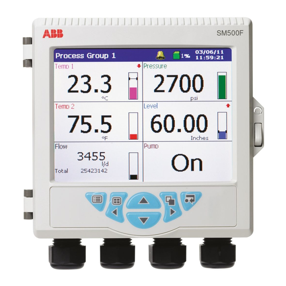
SM500F
Field mountable paperless recorder
Measurement made easy
For more information
Further publications for the SM500F paperless recorder are
available for free download from
and reference numbers below) or by scanning this code:
SM500F field-mountable paperless recorder:
Commissioning instruction
SM500F field-mountable paperless recorder:
Datasheet
www.abb.com
(see links
search for or click on:
CI/SM500F-EN
DS/SM500F-EN
Table of Contents

Related Manuals for ABB SM500F


Summary of Contents for ABB SM500F
- Page 1 User guide IM/SM500F Rev. Z SM500F Field mountable paperless recorder Measurement made easy For more information Further publications for the SM500F paperless recorder are available for free download from www.abb.com (see links and reference numbers below) or by scanning this code:...
- Page 2 Cert. No. Q 05907 As a part of ABB, a world leader in process automation technology, we offer customers EN 29001 (ISO 9001) application expertise, service and support worldwide.
-
Page 3: Table Of Contents
Operator Keys and Door Features ..................25 Operator Display Overview ..................... 26 Chart Views ........................... 27 4.4.1 Electronic Signatures ....................37 Indicator View ........................38 Audit Log View ........................42 Alarm Event Log ........................43 Totalizer Log .......................... 45 IM/SM500F Rev. Z... - Page 4 6.5.3 Binary Format Log files ....................60 6.5.4 Binary Format Data File Examples ................61 6.5.5 Binary Format Data Verification and Integrity ..............62 Archiving Online/Offline ......................63 Backing-up Archived Data ..................... 64 Archive Wrap ......................... 64 IM/SM500F Rev. Z...
- Page 5 7.11.2 Comms Analog Input ....................127 7.11.3 Comms Digital Input ....................129 7.12 Logic Editor ......................... 130 7.13 Math Equations ........................131 7.13.1 Using the Math Block Editor (Math Pad) ..............131 7.13.2 Math Block Configuration ..................133 Specification ..........................134 IM/SM500F Rev. Z...
- Page 6 F.3.2 Starting a Batch Manually ..................174 F.3.3 Stopping a Batch Manually ..................176 F.3.4 Historical Review ....................... 176 Configuration ........................177 F.4.1 Enabling Batch Security ..................... 177 F.4.2 Configuring Batch Access Privileges ................178 F.4.3 Batch Configuration ....................179 Index ..............................181 IM/SM500F Rev. Z...
-
Page 7: Introduction
Integrated web server and file transfer protocol (ftp) support for remote monitoring and data acquisition. The ability to store batch data (if Batch option is enabled). Math and Logic (if Math and Logic option is enabled). IM/SM500F Rev. Z... - Page 8 SM500F Field mountable paperless recorder 1 Introduction Signal sources – see Appendix A, page 146 Process Group 1 Process Group 2 Instrument Logs Fig. 1.1 Functional Overview IM/SM500F Rev. Z...
-
Page 9: Installation
The complete recorder can be hosed down if it has been installed to IP66/NEMA 4X standards, i.e. cable glands are correctly fitted and all unused cable entry holes are blanked off – see Section 2.3.1, page 15. Warm water and a mild detergent can be used. IM/SM500F Rev. Z... -
Page 10: Siting
SM500F Field mountable paperless recorder 2 Installation 2.1 Siting Sensors A Close to Sensors B At Eye-level Location C Avoid Vibration Fig. 2.1 General Siting Requirements IM/SM500F Rev. Z... - Page 11 Select a location away from strong electrical and magnetic fields. If this is not possible, particularly in applications where mobile communications equipment is expected to be used, screened cables within flexible, earthed metal conduit must be used. IM/SM500F Rev. Z...
-
Page 12: Mounting
SM500F Field mountable paperless recorder 2 Installation 2.2 Mounting Dimensions in mm (in.) Fig. 2.3 Mounting Dimensions IM/SM500F Rev. Z... -
Page 13: Panel-Mounting
Tighten the clamping screws evenly and securely by hand. Note. This is critical in order to ensure proper compression of the panel seal and achieve the IP66/NEMA 4X hosedown rating. Fig. 2.4 Installing the recorder – Panel-Mounting IM/SM500F Rev. Z... -
Page 14: Wall-Mounting
Ensure the plastic washers remain in the positions fitted. Mark fixing centers and drill suitable holes in the wall. Secure the recorder to the wall using 2 screws in each mounting bracket. Dimensions in mm (in.) Fig. 2.5 Installing the Recorder – Wall-Mounting IM/SM500F Rev. Z... -
Page 15: Pipe-Mounting (Optional)
Ensure the plastic washers remain in the positions fitted. Secure the recorder to the pipe using the remaining clamp plate, spring lock washers and nuts. Vertical pipe Horizontal pipe Fig. 2.6 Installing the Recorder – Pipe-Mounting (Optional) IM/SM500F Rev. Z... -
Page 16: Electrical Connections
USA or Canada. For connection to mains input and relay contact outputs), use only suitably rated field wiring insulated copper conductors rated min. 300 V, 14 AWG, 90C. Route wires through suitably rated flexible conduits and fittings. IM/SM500F Rev. Z... -
Page 17: Cable Entries
Optional cable glands are available and are suitable for use with cables Ø 5 to 9mm (0.20 to 0.35 in.). The alternative 2-hole cable gland inserts are suitable for use with cables Ø 5mm (0.20 in.). The Ethernet cable gland is suitable for use with cable Ø 4.8 to 6.3mm (0.19 to 0.25 in.). IM/SM500F Rev. Z... - Page 18 SM500F Field mountable paperless recorder 2 Installation Fig. 2.7 Cable Knockouts, Ethernet Cable Routing and Cable Screening Connections IM/SM500F Rev. Z...
-
Page 19: Connections
(BZX79 – B/C2V4) to the input as shown. Fig. 2.8 Electrical Connections Note. Power supply terminal screws must be tightened to a torque of 0.8 Nm (7 lbf.in). All other terminal screws must be tightened to a torque of 0.5 Nm (4.5 lbf.in). IM/SM500F Rev. Z... -
Page 20: Single Analog/Digital Inputs
If 2-lead resistance thermometers are used, each input must be calibrated to take account of the lead resistance. Voltage Current Thermocouple 3-lead RTD 4-lead RTD Digital Input Fig. 2.9 Single Analog/Digital Input Connections Note. Analog/digital input terminal screws must be tightened to a torque of 0.5 Nm (4.5 lbf.in). IM/SM500F Rev. Z... -
Page 21: Dual Analog/Digital Inputs
+ + Voltage Current Thermocouple Input 1 Input 2 Digital Input Fig. 2.10 Dual Analog/Digital Input Connections Note. Analog/digital input terminal screws must be tightened to a torque of 0.5 Nm (4.5 lbf.in). IM/SM500F Rev. Z... -
Page 22: Power Supply Connections
90 V min. to 264 V max. 50/60 Hz 10 V min. to 36 V max. DC Fig. 2.11 Power Supply Connections Note. Power supply terminal screws must be tightened to a torque of 0.8 Nm (7 lbf.in). IM/SM500F Rev. Z... -
Page 23: Transmitter Power Supply Module
A Modbus/digital input module can be fitted in position F to provide a 2-wire isolated RS485 interface and 2 digital inputs. Rx/Tx + Rx/Tx – Dig In 1 Dig In 2 Common Fig. 2.13 Modbus/Digital Input Module IM/SM500F Rev. Z... -
Page 24: Host Computer Serial Communications
– refer to information supplied with the host system. Host Computer +5 V Tx + 1.8 k Pull-up Tx – Terminal Block F Resistor Rx/Tx + Rx + Rx/Tx – Rx – 1.8 k Pull-down Resistor Fig. 2.14 Two-wire Connection IM/SM500F Rev. Z... -
Page 25: Pull-Up And Pull-Down Resistors
2.9.3 Pull-up and Pull-down Resistors To prevent false triggering of slaves when the master (host computer) is inactive, pull-up and pull-down resistors are fitted to the SM500F's Modbus/digital input module. 2.9.4 Termination Resistor For long transmission lines, a termination resistor must be fitted to the last slave in the chain – see Fig. 2.15. -
Page 26: On-Line Help
Repeat the process for sub-sections. Press key to close a sub-section or section. To exit the on-line help, press the key repeatedly to return to the screen from where help was first selected. Fig. 3.1 On-Line Help Overview IM/SM500F Rev. Z... -
Page 27: Operation
Chart, Indicator, Audit Log, Alarm Log or Totalizer Log view to the SD card if is pressed when an operator menu is not displayed. Door Release. Door Lock (optional). Fig. 4.1 Operator Keys and Door Features IM/SM500F Rev. Z... -
Page 28: Operator Display Overview
SM500F Field mountable paperless recorder 4 Operation 4.3 Operator Display Overview Fig. 4.2 Overview of Operator Displays Note. Only process groups and views that are enabled are displayed. IM/SM500F Rev. Z... -
Page 29: Chart Views
, page 28. Note 4 Note. Do not remove media while the media update in progress status icon ( ) is displayed. Always set the external media Off-line before removing it – see page 51. IM/SM500F Rev. Z... - Page 30 Global Alarm status icon ( ) is displayed in either the status bar – see Fig. 4.3. If active alarm in process group is unacknowledged, the either icon is surrounded by a flashing border ( IM/SM500F Rev. Z...
- Page 31 Previously recorded data for the other group can be viewed if the group is enabled and displayed. Historical Review Active Values displayed indicate the process status at the cursor position Cursor IM/SM500F Rev. Z...
- Page 32 Once internal memory becomes full, the oldest data is overwritten by the newest data. If historical review has been selected for some time, the oldest data present may no longer be available. The recorder exits Historical Review mode automatically after 15 minutes if no key is pressed. IM/SM500F Rev. Z...
- Page 33 Messages' annotation is selected (see 'Chart Annotation' below) the message is also added to the chart. Note. When the recorder is in Historical Review mode, Operator Messages generated are added at the current time, not the time indicated by the cursor. IM/SM500F Rev. Z...
- Page 34 Up to 3 days/screen More than 12 seconds, less than 28 seconds Up to 3 days/screen Up to 4.5 days/screen More than 28 seconds Up to 7 days/screen Up to 12 days/screen Table 4.1 Sample Rates and Screen Intervals IM/SM500F Rev. Z...
- Page 35 Traces are identified by the Channel Number (e.g. Ch1.1) and its tag. Note. The recording of a channel's data is not affected by this operation and the instantaneous channel values are still shown on the indicators at the top of the screen. IM/SM500F Rev. Z...
- Page 36 AutoView Scroll is active. Press any key to cancel AutoView Scroll. If only one process group is enabled, AutoView Scroll is greyed-out in the menu (color recorders) or is blanked-out when selected in the menu (monochrome recorders). IM/SM500F Rev. Z...
- Page 37 – length of time for which the recorder has been operational. IP or MAC Address – internet or MAC address assigned to the recorder (display alternates between them) Options enabled – list of enabled software options. Blank if no options have been enabled. IM/SM500F Rev. Z...
- Page 38 Field mountable paperless recorder 4 Operation Note. Displayed only if batch recording has been enabled during Group configuration and a batch is not running – see Appendix F.4.3, page 179. Select to display the Chart view on-line help. IM/SM500F Rev. Z...
-
Page 39: Electronic Signatures
Fig. 4.4 Entering an Electronic Signature Note. Up to 7 electronic signatures can be stored in the instrument’s memory. If 7 signatures exist and a new one is created, the oldest is overwritten. IM/SM500F Rev. Z... -
Page 40: Indicator View
Maximum, minimum and average totalizer values (displayed only if 'Show Statistics' selected from Operator menu). Note. Do not remove media while the media update in progress status icon ( ) is displayed. Always set the external media Off-line before removing it – see page 51. IM/SM500F Rev. Z... - Page 41 Select to reset the totalizer value to the totalizer preset value. Channel totalizers that have not been enabled in the Configuration level are greyed-out in the menu (color recorders) or are blanked-out when selected in the menu (monochrome recorders). IM/SM500F Rev. Z...
- Page 42 AutoView Scroll is active. Press any key to cancel AutoView Scroll. If only one process group is enabled, AutoView Scroll is greyed-out in the menu (color recorders) or is blanked-out when selected in the menu (monochrome recorders). IM/SM500F Rev. Z...
- Page 43 – internet or MAC address assigned to the recorder (display alternates between them) Options enabled – list of enabled software options. Blank if no options have been enabled. Select to display the Indicator view on-line help. IM/SM500F Rev. Z...
-
Page 44: Audit Log View
Select the Configuration Level – see Section 7, page 65. Select the Logging Level – see Section 5.1, page 47. Select to display the Audit Log view on-line help. IM/SM500F Rev. Z... -
Page 45: Alarm Event Log
Alarm becomes inactive (Inactive transition). Operator message. Oldest data – press the key to view the previous page of data. Alarm acknowledged. Newest data – press the key to view the next page of data. Global alarm icon. IM/SM500F Rev. Z... - Page 46 Alarms that have not been configured are greyed-out in the menu (color recorders) or are blanked-out when selected in the menu (monochrome recorders). Select to display the Alarm Event Log view on-line help. IM/SM500F Rev. Z...
-
Page 47: Totalizer Log
Date/time at which the maximum and minimum flowrates occurred. Newest data – press the key to view the next page of data. Note. Maximum, minimum and average statistics are not shown unless enabled in the 'Filter' menu – see page 46. IM/SM500F Rev. Z... - Page 48 These values are reset when the totalizer is reset and are updated only when the totalizer is running. indicates the entries selected. Note. Hiding and displaying log entries does not affect the recording of totalizer data in the log. Select to display the Totalizer Log view on-line help. IM/SM500F Rev. Z...
-
Page 49: Logging
Refer to Fig. 5.2, page 48 to access Logging. Invalid Password Entered Logging Security Enabled Valid Password Entered Logging Security Not Enabled Fig. 5.1 Accessing Logging – Basic Security IM/SM500F Rev. Z... - Page 50 If this occurs, access privileges can be reinstated only by the system administrator (User 1). If the system administrator's access privileges have been removed, the security system must be disabled using the configuration security switch to gain access to the configuration. IM/SM500F Rev. Z...
-
Page 51: Password Entry
Password expired Passwords can be configured to expire at pre-determined intervals. If a password is time expired, this screen is displayed automatically. Enter a new password as described above. IM/SM500F Rev. Z... -
Page 52: Logging Menu
3. Select 'Reset archiving' in the logging menu. 4. Select 'On-line' in the Logging menu. 5. Select data to be archived if >1 hour (Text format) or >1 day (Binary format) of data in internal memory and press IM/SM500F Rev. Z... - Page 53 SD card slot on the back of the door. Use the file viewer to view a list of the files stored in internal memory and on external archive media. Note. Files stored in internal memory cannot be deleted. Select to display the Logging on-line help. IM/SM500F Rev. Z...
-
Page 54: Archiving
To avoid potential damage or corruption to data recorded on an SD card, take care when handling and storing the card. Do not expose the card to static electricity, electrical noise or magnetic fields. When handling the card take care not to touch any exposed metal contacts. IM/SM500F Rev. Z... -
Page 55: Sample Rates
Audit log files *.A** (Note. The content of this file is the same for all groups). Digital signature files *.S** Digital signature file for the corresponding channel data file. Table 6.1 Text Format File Types and Extensions IM/SM500F Rev. Z... -
Page 56: Text Format Archive Files
*Formatted according to the date format set in Common Configuration – see Section 7.6.3, page 76 Table 6.3 New Text File Intervals Note. The 'New File Interval' is set in the Configuration level – see Section 7.7.4, page 90. IM/SM500F Rev. Z... - Page 57 The existing file is closed and a new file is created –filename: 26Oct03ProcessGroup1.D00 The file '26Oct03ProcessGroup1~DS.D00' contains data generated from 00:00:00 to 02:59:59 (before summertime ends). The file '26Oct03ProcessGroup1.D00' contains data generated from 02:00:00 (after summertime ends) IM/SM500F Rev. Z...
-
Page 58: Text Format Filename Examples
Note. Totalizer logs are created only if the totalizer option is enabled. New text format log data files are also created when the daylight saving period starts or ends. Files containing log data generated during the daylight saving period (summertime) have '~DS' appended to the filename. IM/SM500F Rev. Z... -
Page 59: Text Format Data File Examples
Alternatively, detailed graphical analysis of the data can be carried out on a PC using the Company's DataManager data analysis software package. Fig. 6.2 Channel Data File Sample – Text Format Fig. 6.3 Alarm Event Log Sample – Text Format IM/SM500F Rev. Z... -
Page 60: Text Format Data File Digital Signatures
6.4.6 Text Format Data Verification and Integrity When data is saved to the archive media it is checked automatically to verify that the date value stored on the media matches exactly the date value stored in the internal memory. IM/SM500F Rev. Z... -
Page 61: Binary Format Archive Files
When the daylight saving period starts or ends. Note. The recorder's internal clock can be configured to adjust automatically at the start and end of Daylight Saving Time (Summertime) periods – see Section 7.6.3, page 76. IM/SM500F Rev. Z... -
Page 62: Binary Format Log Files
When an existing valid binary log file does not exist on the media card. When the maximum size (65000 entries) is exceeded. When the daylight saving period starts or ends. Files containing log data generated during the daylight saving period (summertime) have “~DS” appended to the filename. IM/SM500F Rev. Z... -
Page 63: Binary Format Data File Examples
Version 6.2 (or later) only of the Company's DataManager data analysis software package. Fig. 6.6 Channel Data File Sample – Binary Format Fig. 6.7 Alarm Event Log Sample – Binary Format IM/SM500F Rev. Z... -
Page 64: Binary Format Data Verification And Integrity
Company's DataManager software package. The log files also contain built-in integrity checks enabling the integrity of the data to be verified by the DataManager software. IM/SM500F Rev. Z... -
Page 65: Archiving Online/Offline
Note. Data stored in the internal memory buffer can still be transferred to the archive media when the archive media is placed on-line again (providing it is not off-line so long that the un-archived data in the internal memory is overwritten). IM/SM500F Rev. Z... -
Page 66: Backing-Up Archived Data
– see Table C.1, page 162 for details. 6.8 Archive Wrap Archiving can be configured to delete the oldest archived data file automatically from the external media when the media approaches its maximum capacity – see 'Wrap', page 91. IM/SM500F Rev. Z... -
Page 67: Configuration
Each user is assigned configuration and/or logging access privileges Each user is assigned one of 3 levels of configuration level access privileges Configurable password expiry times, password failure limits and minimum password length Inactive user disabling IM/SM500F Rev. Z... -
Page 68: Configuration Level Access
'Advanced' – see Section 7.6.4, page 78 Configuration Level Protected (see Section 7.2, page 65) Valid Password Entered Configuration Level Unprotected (see Section 7.2, page 65) Continued in Fig. 7.2 on next page Fig. 7.1 Accessing the Configuration Level IM/SM500F Rev. Z... - Page 69 2. The option to load or retain the security configuration applies only to Advanced Security mode and is available only to the System Administrator (User 1). If a new or existing configuration file is opened by a user other than the System Administrator, the recorder's existing security settings are retained. IM/SM500F Rev. Z...
- Page 70 Tighten the inner cover plate retaining screw and fit a tamper-evident seal (if required). Close and lock the recorder's door and restore the power supply to the recorder. Configuration Level Protected Configuration Level Not Protected Fig. 7.3 Setting the Security Switch IM/SM500F Rev. Z...
-
Page 71: Overview Of Configuration
Press the key to display the menu. Select the next item required and activate using the key. When all configuration changes are complete, select 'Exit' to save or cancel changes. Fig. 7.4 Overview of Configuration Steps IM/SM500F Rev. Z... -
Page 72: Making Changes To Parameters
Press the key to accept the selection. Note. The appropriate data entry box is displayed automatically. Use the key to open the Configuration menu in order to select a different channel. Fig. 7.5 Locating Parameter Settings IM/SM500F Rev. Z... - Page 73 Note. Tags with a high percentage of capital letters and wide characters such as 'W' or 'M' may appear truncated in some Operator views. In such cases, use lower case letters or fewer characters. Refer to Note 1 below 1 2 X 4 Refer to Note 2 below 59.45 Fig. 7.6 Data Entry Dialog Boxes IM/SM500F Rev. Z...
- Page 74 When saving the current configuration to internal storage, it is saved twice, once with the filename 'SM500F.cfg' and again with the filename '
- Page 75 SM500F Field mountable paperless recorder 7 Configuration Fig. 7.7 Exiting Configuration Mode IM/SM500F Rev. Z...
-
Page 76: Common Configuration
Note. When reviewing data, the instrument tag is used to identify the source of the data, therefore it is important to ensure that the instrument tag is unique to each recorder. •1 If this parameter is changed, internally recorded data files are recreated and unarchived data is lost. IM/SM500F Rev. Z... -
Page 77: Screen
All images are saved to a folder on the archive media named 'BMP'. The images are saved even if archiving is set to 'Offline'. If external archive media is not inserted, or is full, the screen capture facility is disabled automatically. Adjust screen brightness. IM/SM500F Rev. Z... -
Page 78: Time
Section 7.7.4, page 90) are compatible with the database feature of Version 6.2 (or later) only of the Company's DataManager data analysis software package. If the status icon is displayed the clock battery must be replaced – contact factory. IM/SM500F Rev. Z... - Page 79 Note. Displayed only if 'Daylight Saving - Enable' is set to 'Auto - Europe'. Note. Displayed only if 'Daylight Saving - Enable' is set to 'Auto - Custom'. Set the start and end of the daylight saving period. IM/SM500F Rev. Z...
-
Page 80: Security
Note. The following parameters: are displayed only if 'Security system' is set to 'Advanced' – see above. can be changed only by the System Administrator (User 1). Indicates status of Logging and Acknowledge security settings – see above. IM/SM500F Rev. Z... - Page 81 If the number of incorrect entries exceeds this limit, the user's access privileges are de-activated and can be reinstated only by the System Administrator (User 1). Passwords have a maximum length of 20 characters. Enter the minimum length required for all new passwords. IM/SM500F Rev. Z...
-
Page 82: Users
Note. When the method of access to the Configuration level is set to 'Password protected' (see Section 7.6.4, page 78) and a user with Configuration level access privileges changes recorder's configuration, the 'Name' of the user is included in the audit log entry. IM/SM500F Rev. Z... - Page 83 (see also page 82). The System Administrator (User 1) can view and/or change the user name, access privileges and password for any other user. Select the user to be viewed/edited. Enter a name for the selected user. IM/SM500F Rev. Z...
- Page 84 Alarm acknowledge – The selected user is able to acknowledge alarms. Note. The System Administrator (User 1) only is able to change the Security settings. Enter an initial password for the selected user. Note. The user may subsequently change this password. IM/SM500F Rev. Z...
-
Page 85: Operator Messages
Note. This signal is edge-triggered. A rising edge (inactive to active) or a falling edge (active to inactive) triggers the addition of the Operator Message to the Alarm Event log. Assign to group 1/Assign to group 2 Select the group(s) to which the message is to apply. IM/SM500F Rev. Z... -
Page 86: Process Group Configuration
Process Group. refer to Appendix A, page 146 for a description of the available sources. Note. This signal is edge-triggered. A rising edge (inactive to active) enables recording. A falling edge (active to inactive) disables recording. IM/SM500F Rev. Z... - Page 87 – see Table 4.1, page 32. Set the Secondary sample rate to between 0.1 seconds and 720 minutes 1 (12 hours). •1 If this parameter is changed, internally recorded data files are recreated and unarchived data is lost. IM/SM500F Rev. Z...
- Page 88 Note. This signal is edge-triggered. A rising edge (inactive to active) switches to the secondary sampling rate. A falling edge (active to inactive) switches to the primary sampling rate. •1 If this parameter is changed, internally recorded data files are recreated and unarchived data is lost. IM/SM500F Rev. Z...
-
Page 89: Configuring The Chart View
Disable indicators to hide the indicators and enlarge the Chart view. Select the amount of historical data to be displayed on the screen. Available selections are limited by the sample rate selected – see Section 7.7.1, page 84 and Table 4.1, page 32. IM/SM500F Rev. Z... - Page 90 Enables the display of Alarm events and Operator messages on the chart to be enabled or disabled by the operator. Note. Menu items that are not enabled are greyed-out (color recorders) or blanked out when selected (monochrome recorders) in the relevant Chart view menu. IM/SM500F Rev. Z...
-
Page 91: Configuring The Indicator View
Alarm Acknowledge Enables the Operator to acknowledge any alarms associated with the current group. Note. Menu items that are not enabled are greyed-out (color recorders) or blanked out when selected (monochrome recorders) in the Indicator view menu. IM/SM500F Rev. Z... -
Page 92: Archiving
Note. The following characters cannot be used in the filename tag: \, /, :, *, ?, ", <, >, |, superscript characters, ~, and º. These are greyed-out (color recorders) or blanked out when selected (monochrome recorders) on the keyboard. IM/SM500F Rev. Z... - Page 93 Automatic update Any un-archived data is saved to Not Applicable removable archive media at regular intervals (approximately every 30 seconds). Table 7.2 Archive Triggers IM/SM500F Rev. Z...
-
Page 94: Batch Recording
SM500F Field mountable paperless recorder 7 Configuration 7.7.5 Batch Recording See Appendix F, page 173. IM/SM500F Rev. Z... -
Page 95: Channel Configuration
All historical data stored internally for this channel is lost. If this parameter is changed from a previous setting of 'None' new internal data files for all enabled recording channels are created. Any unarchived data is lost. IM/SM500F Rev. Z... - Page 96 This allows the memory use to be extended by permitting a slower sample rate to be selected without losing the transient behavior of the signal. •1 If this parameter is changed, internally recorded data files are recreated and unarchived data is lost. IM/SM500F Rev. Z...
- Page 97 Select the lower limit of the log decade range to be displayed on the Chart view scale – refer to Appendix E.4, page 172. Select the upper limit of the log decade range to be displayed on the Chart view scale – refer to Appendix E.4, page 172. IM/SM500F Rev. Z...
-
Page 98: Analog Input Configuration
Standard Inputs Type Min. Max. 5000 Table 7.3 Limits of Electrical Ranges •1 If this parameter is changed to or from 'Volt free digital input', internally recorded data files are recreated and unarchived data is lost. IM/SM500F Rev. Z... - Page 99 – see page 107. If the recorder holds the relationship data between the selected measurement units and totalizer units, the count rate parameter is calculated and displayed automatically. •1 If this parameter is changed, internally recorded data files are recreated and unarchived data is lost. IM/SM500F Rev. Z...
- Page 100 – channel value driven beyond full scale. None – driven in direction of failure. Downscale – channel value driven below zero. •1 If this parameter is changed, internally recorded data files are recreated and unarchived data is lost. IM/SM500F Rev. Z...
-
Page 101: Digital Input Configuration
'W' or 'M' may appear truncated in some Operator views. In such cases, use lower case letters or fewer characters. •1 If this parameter is changed, internally recorded data files are recreated and unarchived data is lost. IM/SM500F Rev. Z... -
Page 102: Alarm Configuration
SM500F Field mountable paperless recorder 7 Configuration 7.8.4 Alarm Configuration Fig. 7.11 High/Low Process Alarms * Refer to Alarm Ack timeout on page 6. Fig. 7.12 High/Low Latch Alarms IM/SM500F Rev. Z... - Page 103 SM500F Field mountable paperless recorder 7 Configuration * Refer to Alarm Ack timeout on page 6. Fig. 7.13 High/Low Annunciate Alarms IM/SM500F Rev. Z...
- Page 104 SM500F Field mountable paperless recorder 7 Configuration Fig. 7.14 Fast-/Slow-Rate Alarms IM/SM500F Rev. Z...
- Page 105 SM500F Field mountable paperless recorder 7 Configuration Fig. 7.15 Delayed High/Low Process Alarms IM/SM500F Rev. Z...
- Page 106 Note. Annunciate alarms only – see Fig. 7.13, page 101. Set the value, in engineering units, at which the alarm is to activate. Set the time hysteresis in seconds. IM/SM500F Rev. Z...
- Page 107 Set the filter time to be used to reduce the number of spurious alarm trips. The source signal is averaged over the filter period prior to the rate alarm being determined. IM/SM500F Rev. Z...
- Page 108 Assign the alarm to one or more of 12 groups. The alarm states assigned to each group are 'ORed' together to create an internal digital signal that may be assigned to relays, digital outputs or internal digital controls. IM/SM500F Rev. Z...
-
Page 109: Totalizer Configuration
(i.e. quantity per unit of time, for example, gallons per hour) – see page 97. If the recorder holds the relationship data between the measurement units and the totalizer units selected, the count rate parameter (see below) is calculated and displayed automatically. IM/SM500F Rev. Z... - Page 110 'Preset count' value or 'Predetermined count' value. Set the 'Intermediate count' value – the value at which a digital source is activated. This can be used as an alarm threshold to indicate when the 'Predetermined count' value is about to be reached. IM/SM500F Rev. Z...
- Page 111 30 minutes 0, 30 minutes past the hour 60 minutes On the hour 2 hours Midnight, 2am, 4am, etc. 3 hours Midnight, 3am, 6am, etc. 4 hours Midnight, 4am, 8am, etc. 8 hours Midnight, 8am, 4pm, etc. 12 hours Midnight, 12am 24 hours Midnight IM/SM500F Rev. Z...
- Page 112 'Predetermined count' value – see page 108. The totalizer cut off value is the lowest input value (in engineering units) at which the totalizer is to stop counting. IM/SM500F Rev. Z...
- Page 113 0.00001 and 1000.00000. The totalizer is then incremented by this amount each time there is an off/on transition. Example – a count of 5 digital pulses with 'Count rate' set to 100 increments the totalizer from 0 to 500 in 100 unit steps. IM/SM500F Rev. Z...
-
Page 114: F0 (Sterilization Optimization) Configuration
Enter the F0 tag to be displayed in the Indicator view and the Totalizer log archive (6 characters max). Note. The default tag text includes 'F0' to distinguish an F0 value in the totalizer log but this can be changed. IM/SM500F Rev. Z... - Page 115 Set the 'Intermediate count' value – the value at which a digital source is activated. This can be used as an alarm threshold to indicate when the 'Predetermined count' value is about to be reached. IM/SM500F Rev. Z...
- Page 116 12 hours Midnight, 12am 24 hours Midnight Set the required F0 cut off value. The cut off value is the minimum temperature value (T) used in the F0 value calculation. Temperatures read below this value are ignored. IM/SM500F Rev. Z...
-
Page 117: Functions
– see 'Linearizer Type', page 96. Note. X is input to the linearizer expressed as a percentage of the electrical range. Y is output expressed as a percentage of the engineering range. IM/SM500F Rev. Z... -
Page 118: Real-Time Alarms
'Minutes' setting) or on the hour (if 'Minutes' is set to 'Off'). Set the duration for the alarm to remain active. Set to 'On' to add an entry to the Alarm event log each time the real-time alarm becomes active. IM/SM500F Rev. Z... -
Page 119: I/O Module Configuration
Manually fine-tune inputs to remove process offset errors or system scale errors. Note. Changes to the Analog Input Type (see page 96) must be saved to the current configuration before commencing input adjustment. For dual input modules, 2 channels can be adjusted. IM/SM500F Rev. Z... - Page 120 2-lead resistance thermometers, either connect the resistance box at the sensor end of the leads or add the lead resistance to the calibration values. Without Adjustment With Adjustment (Span Adjust = 1, Offset Adjust = 0) (typical example) IM/SM500F Rev. Z...
-
Page 121: Relay Modules
5Hz. Consideration must also be given to the mechanical life of the relay. Select the relay source polarity. Note. When polarity is set to 'Positive', the relay is energized when the digital source is active (On). IM/SM500F Rev. Z... -
Page 122: Ethernet Module
ID, e.g. 255.255.255.0 indicates that the first 24 bits are for the network ID. Set the IP address for the 'default gateway (router, switch etc.) required to communicate with other networks. This setting may not be required. The default setting is '0.0.0.0'. IM/SM500F Rev. Z... - Page 123 – user cannot log on to the recorder from a web browser. Note. If a user is given full access via FTP, that user is able to delete both data and configuration files. This could result in erroneous operation of the recorder. IM/SM500F Rev. Z...
-
Page 124: E-Mail
To prevent this, allocate a fixed IP address to the recorder and ensure this IP address is explicitly allowed as valid in the configuration of the email server (and any intervening firewalls). Enter the IP address of the SMTP server through which e-mails are to be routed. Enter the address(es) of the e-mail recipient(s). IM/SM500F Rev. Z... - Page 125 Event trigger source types that cannot be inverted are: Alarm acknowledge, Any alarm and New alarm. Select up to 10 event source types to generate an e-mail. IM/SM500F Rev. Z...
-
Page 126: Rs485 (Modbus™) Communications
Modbus link. Note. Maximum 31 slaves per loop. Set to the Baud rate used by the host system: 1200, 2400, 4800, 9600, 19200, 38400, 115200. Set to the Parity used by the host system: None, Odd, Even. IM/SM500F Rev. Z... -
Page 127: Modbus Tcp
Note. Displayed only if 'Implementation' is set to 'Modbus TCP Server'. All analog data is read from the recorder in IEEE format contained in adjacent registers representing the data in high word, low word order. Select 'Yes' to reverse the IEEE data, otherwise select 'No'. IM/SM500F Rev. Z... -
Page 128: Client Authorization
Note. Displayed only if 'TCP Client Access' set to 'Unrestricted'. is not Enter the IP address(es) of the Modbus TCP Client (Modbus Master) device(s) that is(are) permitted to poll the recorder for data. IM/SM500F Rev. Z... -
Page 129: Comms Analog Input
Note. Displayed only if 'Protocol' is set to 'TCP' or 'RTU'. Enter the register number to be read in the slave device. Note. Displayed only if 'Protocol' is set to 'TCP' or 'RTU'. Select the register type, 'Holding Register' or 'Input Register'. IM/SM500F Rev. Z... - Page 130 – signed, 32 bit integer, transmitted in high/low order rev. Sint32 – signed, 32 bit integer, transmitted in low/high order IEEE – 32 bit floating point number, transmitted in high/low order Rev. IEEE – 32 bit floating point number, transmitted in low/high order IM/SM500F Rev. Z...
-
Page 131: Comms Digital Input
Note. Displayed only if 'Protocol' is set to 'TCP' or 'RTU'. Enter the register number to be read or written to in the slave device. Note. Displayed only if 'Protocol' is set to 'TCP' or 'RTU'. Select the register type, 'Input Status' or 'Coil Status'. IM/SM500F Rev. Z... -
Page 132: Logic Editor
Repeat these steps until the equation is complete. Enter an equation tag (20 characters maximum) to be displayed in the Alarm Event log. Set to 'On' to enable changes in the equation's state to be recorded in the Alarm Event log. IM/SM500F Rev. Z... -
Page 133: Math Equations
For further information regarding math equations and functions, refer to Appendix E, page 165. 7.13.1 Using the Math Block Editor (Math Pad) Select Math Blocks 7 to 8 Launches Math Pad – see Fig. 7.19 Fig. 7.18 Launching the Math Block Editor (Math Pad) IM/SM500F Rev. Z... - Page 134 Return to Main Math Block screen Source Configuration see Section 7.13, page 131 Fig. 7.19 Math Pad Note. Use the button to change the configuration of the selected channel source, without the need to exit the math block configuration sequence. IM/SM500F Rev. Z...
-
Page 135: Math Block Configuration
(16 characters max.). Note. Tags with a high percentage of capital letters and wide characters such as 'W' or 'M' may appear truncated in some Operator views. In such cases, use lower case letters or fewer characters. IM/SM500F Rev. Z... -
Page 136: Specification
A user is deactivated if a wrong password is entered repeatedly Deactivation of Can be disabled or configured for 7, 14, 30, 60, 90, inactive users 180 or 360 days of inactivity Users are deactivated (by removal of access privileges) after a period of inactivity IM/SM500F Rev. Z... - Page 137 Chart divisions Programmable for up to 10 major and 10 minor divisions Chart annotation Alarm and operator messages may be annotated on the chart Icons to identify the type of event, time of occurrence and tag are displayed IM/SM500F Rev. Z...
- Page 138 Primary/Secondary sample rates Programmable from 0.1 s to 12 hours for each process group Primary/Secondary sample rate selection Via any digital signal or from password protected menu Recording start/stop control Via any digital signal or from password-protected menu IM/SM500F Rev. Z...
- Page 139 ABB recorders comply with approved industry standards for memory cards and ABB fully tests any memory card they supply for compatibility with this device. Other cards not supplied by ABB may not be fully compatible with this device and therefore may not function correctly.
- Page 140 1 Gb SD 2 years 20 years Comma-separated File Sample Rate 128 Mb SD 28 days 9 months 256 Mb SD 8 weeks 19 months 512 Mb SD 16 weeks 3 years 1 Gb SD 7 months 6 years IM/SM500F Rev. Z...
- Page 141 units of – – – – measurement* Max., min. and average values – – – – plus units* Secure total – – – – * If Totalizer option is enabled and selected IM/SM500F Rev. Z...
- Page 142 Programmable as upscale or downscale Temperature stability 0.02 %/°C or 2 µV/°C Long term drift <0.2 % of reading or 20 µV annually Input impedance >10 M (millivolts inputs) >10 M (voltage inputs) 44 (mA inputs) Analog/Digital resolution 16 bit IM/SM500F Rev. Z...
- Page 143 * For B, R, S and T thermocouples, accuracy is not guaranteed below the value stated. Maximum Range °C Maximum Range °F Accuracy (% of reading) PT100 –200 to 600 –325 to 1100 0.1 % or ±0.5 °C (0.9 °F) IM/SM500F Rev. Z...
- Page 144 4 independently configurable users with full or read-only access Web server functions Operator screen monitoring/selection. Remote monitoring of recording channels, analog/digital signals, alarms, totalizers and archiving SMTP client compatibility Compatible with MS Exchange versions up to and including MS Exchange 2003 IM/SM500F Rev. Z...
- Page 145 +, –, /, log, Ln., Exp, X , Sin, Cos, Tan, mean, rolling average, standard deviation, high/median/low select, multiplexer, absolute, relative humidity Tags 8- and 20-character tags for each block Update rate 1 enabled Math block is updated every 100 ms IM/SM500F Rev. Z...
- Page 146 No effect for interrupts of up to 20 ms Safety General safety EN61010-1 Overvoltage Class III on mains, Class II on inputs and outputs Pollution category 2 CSA 61010-1 UL 61010-1 Isolation 500 V DC to earth (ground) IM/SM500F Rev. Z...
- Page 147 138 mm (5.43 in.) x 138 mm (5.43 in.) x 67 mm (2.7 in.) behind panel Case material Glass-filled polycarbonate Operator keypad Tactile membrane keys No. of keys Cable gland entries 4 x 22.2 mm (0.87 in.) o.d. entries for in. NPT glands DS/SM500F–EN Rev. AE IM/SM500F Rev. Z...
-
Page 148: Appendix A - Signal Sources
Active when the removable archive media is 100% full Active when the removable archive media is 80% full. Archive 80% full Arc media present Active when the removable archive media is present. Archive on-line Active when archiving is in progress. Table A.1 Signal Sources IM/SM500F Rev. Z... - Page 149 Active for 100ms each time the totalizer updates by one whole count. E.g. if two Count pulse 1.1 to 2.6 decimal places are set, a pulse is generated when the totalizer value increments from 0.99 to 1.00 or 1.99 to 2.00 (Continued) Table A.1 Signal Sources IM/SM500F Rev. Z...
-
Page 150: Appendix B - Modbus Tcp/Modbus 485
16 Preset Multiple Registers – The recorder carries out updates that are valid and generates an exception response if any of the registers are not currently writable. IM/SM500F Rev. Z... -
Page 151: Modbus Exception Responses
The instrument monitors the elapsed time between receipt of characters from the host. If the elapsed time between two characters is 3.5 character times, the slave assumes the second character received is the start of a new message. IM/SM500F Rev. Z... -
Page 152: Operating Mode Modbus Coils
Tables B.2 to B.10 detail the contents of each Modbus coil. Each coil is assigned a register that can have one of two values: 0000 and 0001. Read Only: 0 = Input OK, 1 = Input Failed Analog Input Modbus Coil 0001 0002 0005 0003 0006 0004 0007 Table B.2 Analog Input Fail States IM/SM500F Rev. Z... - Page 153 2.5C 0093 0143 1.5D 0086 0136 2.5D 0094 0144 1.6A 0087 0137 2.6A 0095 0145 1.6B 0088 0138 2.6B 0096 0146 1.6C 0089 0139 2.6C 0097 0147 1.6D 0090 0140 2.6D 0098 0148 Table B.3 Alarm States IM/SM500F Rev. Z...
- Page 154 1 = Remote operator message assigned 1 = Assign remote operator message to 0182 to group group Activate Remote 0 = No effect 0183 Always reads as 0 Operator Message 1 = Activate Table B.5 Remote Operator Messages IM/SM500F Rev. Z...
- Page 155 0474 0524 0574 * Time since last reset Table B.6 Totalizer Digital Signals Read Only: 0 = All alarms inactive 1 = At least 1 alarm active Title Coil Number Any Alarm 0750 Table B.7 Any Alarm IM/SM500F Rev. Z...
- Page 156 Read Only: 0 = Real time alarm inactive 1 = Real time alarm active Title Coil Number Real Time Alarm 1 0851 Real Time Alarm 2 0852 Real Time Alarm 3 0853 Real Time Alarm 4 0854 Table B.9 Real Time Alarms IM/SM500F Rev. Z...
- Page 157 Channel Type Read Only 1020 1050 1080 1110 1260 1290 1140 1170 1200 1230 1320 1350 Digital Value Read Only 1021 1051 1081 1111 1261 1291 1141 1171 1201 1231 1321 1351 Table B.10 Channel Digital Signals IM/SM500F Rev. Z...
-
Page 158: Operating Mode Modbus Registers
1.3C 0121 and 0122 1.6C 0177 and 0178 2.3C 0153 and 0154 2.6C 0193 and 0194 1.3D 0123 and 0124 1.6D 0179 and 0180 2.3D 0155 and 0156 2.6D 0195 and 0196 Table B.12 Alarm Trip Levels IM/SM500F Rev. Z... - Page 159 0296 0346 0396 0492 0596 0646 0696 0792 0297 and 0347 and 0397 and 0493 to 0597 and 0647 and 0697 and 0793 to 2.6B 0298 0348 0398 0496 0598 0648 0698 0796 Table B.13 Totalizer Totals IM/SM500F Rev. Z...
-
Page 160: Communications - Analog And Digital Inputs
0893 and 0894 0611 0661 0871 and 0872 0623 0673 0895 and 0896 0612 0662 0873 and 0874 0624 0674 0897 and 0898 Reserved 0625 to 0650 0675 to 0700 0899 to 1000 Table B.14 Modbus Inputs IM/SM500F Rev. Z... - Page 161 1326 1376 1526 1576 1027 1077 1127 1177 1427 1477 1227 1277 1327 1377 1527 1577 Totalizer A Read Total Only 1030 1080 1130 1180 1430 1480 1230 1280 1330 1380 1530 1580 Table B.15 Channel Data IM/SM500F Rev. Z...
- Page 162 Field 1 1826 to 1845 Field 2 1751 to 1770 Field 2 1851 to 1870 Field 3 1776 to 1795 Field 3 1876 to 1895 Table B.16 Batch Fields (Unicode Format as Table B.18 but Prefixed with ’00’). IM/SM500F Rev. Z...
- Page 163 Space “ & < > Char £ ° ² ³ µ Note. Character codes 2C, 60 and 7F Hex (44, 96 and 127 Dec) are not supported Table B.18 ASCII Character Set for Remote Operator Messages IM/SM500F Rev. Z...
-
Page 164: Appendix C - Storage Capacity
SD Card Size Sample Rate 128Mb 256Mb 512Mb 1.0 second 3 months 6 months 12 months 2 years 10.0 seconds 2.5 years 5 years 10 years 20 years Table C.3 External (Archive) Storage Capacity – Binary Formatted Archive Files IM/SM500F Rev. Z... -
Page 165: Appendix D - Units
%dO2 % dissolved oxygen m3/s cubic meters per second microvolts ft3/d cubic feet per day millivolts ft3/h cubic feet per hour megavolts Table D.1 Engineering Units IM/SM500F Rev. Z... - Page 166 (US) us gallons x 100 Mft3 mega cubic feet volume of water, 1ft deep, kgal (US) us kilo gallons AcreFt covering an area of 1 acre Mgal (US) us mega gallons Custom user defined units Table D.2 Totalizer Units IM/SM500F Rev. Z...
-
Page 167: Appendix E - Math Equations
Digital signals (md1 to md3) are evaluated as 0 (inactive) and 1 (active), therefore in the example: m1 = a1 + a2 x md1 the sum of (a1+ a2) is set to zero if the digital input md1 is also zero. IM/SM500F Rev. Z... -
Page 168: Math Functions
Returns the variable with the smallest magnitude Mux(x, y, s) Selects x if s is false, otherwise y Power Functions: (x, a) Raises the variable x to the power a Sqr(x) Returns the square root of variable x Table E.1 Math Functions IM/SM500F Rev. Z... -
Page 169: Relative Humidity Calculation
Inputs used for wet and dry bulb measurement must be in the ranges 0 to 100°C or 32 to 212°F. The result must be set to 0 to 100.0% RH. Fig. E.1 (page 168) is an example of configuring a math block to perform a relative humidity calculation. IM/SM500F Rev. Z... - Page 170 SM500F Field mountable paperless recorder Appendix E – Math Equations Fig. E.1 Relative Humidity Calculation IM/SM500F Rev. Z...
-
Page 171: Sterilization Fvalue Calculation
D, but is typically 30% of the total cycle time. It is in the area, C D, and E F, that Fvalues make their contribution to shortening sterilization time, by accumulating credit for the time spent approaching and receding from the sterilizing temperature. IM/SM500F Rev. Z... - Page 172 As Fvalue calculation is an integrating function, the sample rate has a direct effect on the accuracy when the temperature is changing. With a steady state signal the sample rate does not affect accuracy. Fig. E.3 is an example of configuring a math block to perform a sterilization Fvalue calculation. IM/SM500F Rev. Z...
- Page 173 SM500F Field mountable paperless recorder Appendix E – Math Equations Fig. E.3 Sterilization Fvalue Calculation IM/SM500F Rev. Z...
-
Page 174: Logarithmic Scales
Note. Regardless of the scale type setting: All alarms on the recording channel are triggered by the channel's linear value. Data values saved to the archive files are the linear output from the recording channel. IM/SM500F Rev. Z... -
Page 175: Appendix F - Batch Recording
An additional batch log archive file is created that contains all the identification data for each batch. These have a filename formatted as follows: Start TimeStart Date {~DS}{_n}.Xnn The Alarm Event Log archive files also contain details of all batch start and stop events. IM/SM500F Rev. Z... -
Page 176: Operation
If 'Batch Number' is set to 'Text' during configuration, this field is blank. A text entry keyboard is displayed when the edit button is selected to enable a batch label to be entered manually (max. 20 characters). IM/SM500F Rev. Z... - Page 177 The operator's name is displayed if 'Operator login' is not set to 'Disabled' – see page 179. Select 'OK' to accept changes and start batch recording. Select 'Cancel' to return to the chart view without starting batch recording. IM/SM500F Rev. Z...
-
Page 178: Stopping A Batch Manually
Select to move to data recorded in the instrument’s onboard memory for a specific batch. Select the batch to be reviewed from the list. The data is displayed from the start of the batch. IM/SM500F Rev. Z... -
Page 179: Configuration
Section 7.6.4, page 78. If the 'Security system' parameter is set to 'Basic', batch security is automatically disabled and cannot be enabled. To enable batch security, access Common Configuration (see Section 7.6.4, page 78) and select the 'Security ' tab. Set to 'Advanced' to enable batch security. IM/SM500F Rev. Z... -
Page 180: Configuring Batch Access Privileges
Ensure the 'Batch' field is ticked to allow User 1 to start and stop batches – see Section F.3, page 174. Repeat as required for other Users. Refer to page 179 to set the required type of batch recording security. IM/SM500F Rev. Z... -
Page 181: Batch Configuration
'Basic' this parameter is set automatically to 'Disabled' and the edit button is not displayed. If this parameter is set to 'Disabled' no security is required to start or stop batch recording and the operator name is not displayed. IM/SM500F Rev. Z... - Page 182 It is important to configure Field 1 because it is used, together with the batch number, to identify a batch: – on chart annotations – in the alarm event log – during historical review – in the DataManager display/search functions Exit and save the configuration. IM/SM500F Rev. Z...
-
Page 183: Index
Electronic signatures ......................... 37 Audit log ........................42, 53, 54, 90 Bargraph ............................. 5, 38 Enabling ............................ 89 Batch access privileges ......................82, 178 Batch recording ......................92, 174 to 180 Binary format archive files ....................... 59 to 62 IM/SM500F Rev. Z... - Page 184 Recording parameters ...................... 84 to 86 Sample rates ..........................85 Security ........................65, 78 to 79 Access privileges ........................82 Inactive user de-activation ...................... 79 Passwords ..........................79 Type ............................78 View/edit other users ......................80, 81 Totalizers ........................107 to 111 IM/SM500F Rev. Z...
- Page 185 Recording channel input ......................94 Filter time ..........................98 Functional overview ........................... 5 Functions ..........................115 to 116 Historical Review ......................31, 174, 176 Historical review ......................29, 31, 32, 51 Enable ............................88 Exit ............................31 Goto ............................30 IM/SM500F Rev. Z...
- Page 186 Modbus inputs ......................... 158 Operator messages ......................... 152 Real time alarms ........................154 Remote operator messages ..................... 152, 161 Reverse IEEE data ........................125 Server (Modbus slave) ...................... 125, 126 TCP client access ......................125, 126 TCP/IP port ..........................125 IM/SM500F Rev. Z...
- Page 187 Setting the security switch ....................... 68 Setup level Recording control ........................50 Signal sources ..........................146 Simulated inputs ..........................96 Span adjust ........................... 118 Storage capacity External ........................... 162 Internal ............................ 162 System administrator ......................... 78, 79 IM/SM500F Rev. Z...
- Page 188 Filter ............................46 Update frequency ........................109 Totalizers Count direction ........................107 Count rate ..........................110 F0 value calculation ........................112 Preset count ..........................108 Tag ............................107 Units ..........................107, 164 Wrap ............................107 Trace Width ............................88 IM/SM500F Rev. Z...
- Page 189 Repair Centre. — Metals and Minerals — Oil, Gas & Petrochemical — Pulp and Paper ABB Limited Tel: +44 (0)1480 475321 Drives and Motors Fax: +44 (0)1480 217948 — AC and 6 Drives, AC and DC Machines, AC Motors to —...
- Page 190 With regard St. Neots to purchase orders, the agreed particulars Cambridgeshire PE19 8EU shall prevail. ABB does not accept any responsibility whatsoever for potential errors or possible lack of information in this Tel: +44 (0)1480 475321 document.