Table of Contents
Quick Links
ATTENTION
The inverter manufactured in our company is only applied to the elevator.
Use this equipment before ensuring the safety and application of the
elevator.
Always take safety precautions such as dual safety mechanism and
malfunction protection.
Failure to do so could lead to serious accident.
Panasonic Electric Works SUNX Shanghai Co., Ltd.
http://panasonic-electric-works.net/sunx
T52-3, No.1510, Chuanqiao Road, Jinqiao Export Processing Zone,
Pudong New Area, Shanghai, China
Phone: +86-21-5032-3800 FAX: +86-21-5032-3866
Europe Headquarter: Panasonic Electric Works Europe AG
Rudolf-Diesel-Ring 2, D-83607 Holzkirchen, Germany
Phone: +49-8024-648-0
US Headquarter: Panasonic Electric Works Corporation of America
629 Central Avenue New Providence, New Jersey 07974 USA
Phone: +1-908-464-3550
Panasonic Electric Works SUNX Co., Ltd. 2010
©
8A3 708 0000 3
PRINTED IN CHINA
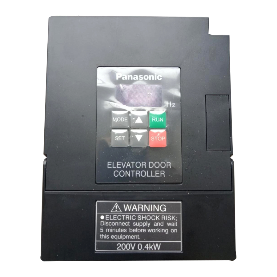
Elevator Door Controller
AAD03011
Instruction Manual
8A3 708 0000 3
panasonic-electric-works.net/sunx
[Support model]
・AAD03011
Read this manual carefully before
attempting to operate the inverter
and store it for further reference.
Panasonic Electric Works SUNX Shanghai
Table of Contents

Related Manuals for Panasonic AAD03011


Summary of Contents for Panasonic AAD03011
- Page 1 Phone: +86-21-5032-3800 FAX: +86-21-5032-3866 Europe Headquarter: Panasonic Electric Works Europe AG Rudolf-Diesel-Ring 2, D-83607 Holzkirchen, Germany Phone: +49-8024-648-0 US Headquarter: Panasonic Electric Works Corporation of America 8A3 708 0000 3 629 Central Avenue New Providence, New Jersey 07974 USA Phone: +1-908-464-3550 panasonic-electric-works.net/sunx...
- Page 3 Foreword Thank you for purchasing the AAD03011 inverter produced by Panasonic Electric Works SUNX Shanghai Co., Ltd. This manual introduces the usage and precautions. Read the manual carefully before using the product. Safety Precautions Read this manual and related documents before attempting to install, operate, service or inspect the inverter.
- Page 4 1. Installation Note Install the unit on a non-combustible material such as metal. Installing it on other material could lead to fires. Do not place the unit near flammable materials. Doing so could lead to fires. Do not hold by terminal cover during transportation. Doing so could cause the unit to drop and lead to injuries.
- Page 5 Note Do not connect an AC power supply to the output terminals (U, V, W). Doing so could lead to injuries or fire. Connect the correct wiring for the motor. If the wiring is incorrect, the door control cannot operate properly. Failure to do so could lead to injuries.
- Page 6 Always confirm the security and function operation of the elevator before obstacle detection function is applied. Failure to do so could lead to injury. Make sure to input safety sensor in the main controller of the elevator and to operate the door's obstacle detection on the main controller side. Obstacle detection function of the inverter does not operate in CLOSE arrival area.
- Page 7 Note The heat sink fins and brake resistor can reach high temperatures, so do not touch them. Doing so could lead to burns. The inverter can be easily set to run from low speeds to high speeds. Confirm the tolerable range of the motor and machine before starting operation.
- Page 8 Note Have an electrician periodically tighten the terminal screws. Loosening of the terminal screws could lead to overheating or fire. 5. Others Caution Do not use the inverter for a load other than a three-phase induction motor. Never disassemble or modify the inverter. Doing so could lead to electric shock or injury.
-
Page 9: Table Of Contents
Table of Contents Page Points for Handling Special Precautions 9 10 Installation Outline Dimensions Parts Identification 13 15 Wiring (Main Circuit) 16 17 Wiring(Control Circuit) 18 22 Operation(Basic Operation) 23 28 Function of each modes 29 33 Setting and Changing Function 34 35 Functional Descriptions (Parameter Table) 36 40... -
Page 10: Points For Handling
Points for Handling Follow this manual and precautions when handling the inverter. Incorrect handling could lead to inhibited operation or a drop operating life. In the worst case, the inverter could be damaged. Use within + 10%, -15% of the tolerable input Power supply voltage range, and within 5% of the tolerable... -
Page 11: Special Precautions 9
Special Precautions To meet requirements of European standard directive, please refer to precautions on Page 98. Use the inverter only within tolerable ambient temperature range.(-10 to 50 ) Because the life of the inverter is greatly affected by ambient temperature, use it within tolerable temperature range. - Page 12 Do not use the inverter for loads other than a three-phase induction motor. Precautions regarding Inverter's Protection Function Various protection functions such as stall prevention, current limit, overcurrent shut-off are built in the inverter. These protection functions are used to protect the inverter from the sudden abnormal conditions in use, so they are not the control functions to be always used.
-
Page 13: Installation
Installation Note Install the unit on a non-combustible material such as metal. Installing it on other material could lead to fire. Do not place the unit near flammable materials. Failure to do so could lead to fire. Do not hold the terminal cover during transportation. Failure to do so could cause the unit to drop and lead to injuries. -
Page 14: Outline Dimensions
Outline Dimensions 5 ( Mounting holes) Unit: mm... - Page 15 Parts Identification Mounting hole Frame Operation panel Communication terminal cover Warning label Rating Terminal nameplate cover Control wire lead-in hole Main circuit wire Check the rating nameplate to confirm lead-in hole that the ordered product has been delivered. Heat sink fins Brake resistor Mounting hole Note) The brake resistor is built into the...
- Page 16 Explanation of Inside of Terminal Cover Communication circuit terminal block (RS485 communication) Control circuit terminal Control circuit terminal block block (Relay output) (Input and output signal) Earth terminal Mounting hole Note) This explanatory drawing shows the state with the terminal cover removed.
- Page 17 Explanation of Operation Panel UP) button Main display RUN button MODE button MODE STOP button STOP SET button DOWN) button The output frequency, output current, line speed, control Main display status monitor, data for function setting and parameter No. are displayed. RUN button The switch is used to start the inverter.
- Page 18 Wiring (Main Circuit) Caution Always confirm that the input power is OFF before starting wiring. Wait at least five minutes after turning the input power OFF before starting wiring. Failure to do so could lead to electric shocks, fires or injuries. Always connect the earth.
- Page 19 Wiring (Main Circuit Terminal) Ground marking Screw size Power supply Main circuit terminal: M4 Grounding terminal: M4 Brake resistor Main circuit terminals connection Ground terminal terminal Circuit breaker (MCCB) Class D(3) grounding Motor Note) Always connect protective devices such as fuse for overcurrent, short circuits and leakage protection to the input terminal.
- Page 20 Control Circuit Wiring Wiring (Control Circuit Terminal) To meet requirements of European standard directive, please refer to precautions on Page 98. Common Common Input signal Encoder signal Built-in power supply specification: 12 V DC -10%/ +20%, 0.1A or less Note1) Do not use the Built-in power supply for other devices except for the encoder power supply.
- Page 21 Wiring ( Communication Terminals) Terminals to connect personal computers and PLCs by the RS485 communication. Transmission line + terminal Terminator RS485 (RS485 communication) Transmission line - terminal (RS485 communication) Terminator terminal (RS485 communication) Related parameter No. P35 to P40. Connect the D+ side and D+ side, and D- side and D- side of the communication terminals.
- Page 22 Explanation of Control Circuit Terminals Terminal Related Parameter Terminal Function Input terminal of Open Signal (forward run operation) Input terminal of Close Signal (reverse run operation) P43,P45,P47,P76, Input terminal of Open arrival signal P43,P45,P47,P76, Input terminal of Close arrival signal P43,P44 Input terminal of safety sensor Input terminal of Open speed change signal...
- Page 23 Precautions on Wiring 1. Use shielded wires for all control signal wires and keep them away more than 20cm from power lines and strong electric circuits. 2. The wiring length of the control signal wire is 30m or less. 3. The control circuit's input signal is a minute signal, so use two minute signal contacts in parallel or use a twin contact to prevent contact faults when inputting the contact.
- Page 24 Note4) Control the cable wiring length of the encoder within 5m or less. Note5) The max. input pulse frequency and the min. input pulse width should be used at the following setting. Max. input pulse frequency (1/T) : 10 kHz or less Phase difference (t1): 25 s or more Overlap (t2) : 25 s or more Phase A...
- Page 25 Operation (Basic Operation) ! Caution Always close the terminal cover before turning the input power ON. Do not open the terminal cover while the power is ON. Failure to do so could lead to electric shock. Do not operate the buttons with wet hands. Failure to do so could lead to electric shock.
- Page 26 Depending on the start mode function setting, if "the fault trip is reset" or "the stop state is released with the panel STOP function" or "door width measurement is reset" when the run signal is input, the inverter may restart suddenly.
- Page 27 Setting the Frequency and Forward/Reverse Run Function With the Operation Panel There are following methods for setting the frequency and carrying out forward/reverse run function with the operation panel. Frequency setting: [Digital setting method] Forward/reverse run operation: [Forward run/reverse run method] [Start/stop, rotation direction mode setting method] 1 Setting the frequency 1 Digital setting method (Parameter P09 set to "0")
- Page 28 Operating With the Operation Panel -1 (Factory Setting State) Forward /reverse run function: Start/stop, rotation direction mode setting (Parameter P08=0) Frequency setting: Digital setting (Parameter P09=0) [Example for rotating in forward direction at operating frequency 5Hz] Main display Power ON The main display lamp will turn ON.
- Page 29 [Continued from previous page, Example for rotating in reverse direction at operating frequency 10Hz] Main display MODE Press the MODE button. MODE Press the MODE button. Changing Press the SET button. (The main display will flicker.) the rotation direction Press the (up) button. (The main display will flicker.) Press the SET button to set the data.
- Page 30 Operating With the Operation Panel -2 Forward / reverse run function: Forward run/reverse run operation (Parameter P08=1) Frequency setting: Digital setting (Parameter P09=0) [Example for rotating in forward direction at operating frequency 5Hz] Main display Power ON The main display lamp will turn ON. MODE Press the MODE button.
- Page 31 Function of each modes The inverter has the following five modes. Output frequency current display mode, Frequency setting monitor mode, Rotation direction setting mode, Control state monitor mode, Function setting mode Normally, use in the output frequency current display mode. This mode is entered when the voltage is applied.
- Page 32 [Continued from previous page] Custom mode After the parameter set currently is confirmed, Function parameter data distributed to The data of the parameter can custom parameter No. can be set, be changed when SET button changed or confirmed. is pressed. Set the required No.
- Page 33 Control State Monitor The following 17 items can be monitored in the control state monitor mode. Monitor Monitor item Indication Output frequency(unit: Hz) Output frequency Output current Output current (unit: A) Output voltage (unit: V AC) Output voltage Internal DC voltage (unit: V DC) Internal DC voltage Setting frequency (unit: Hz) Setting frequency...
- Page 34 Door position area (n07) Indicates the operation area of the door position. [0]: CLOSE hold operation area, [1 to 6]: OPEN operation area [7]: OPEN hold operation area, [8 to 13]: CLOSE operation area Door position (n08) Indicates the data value of the door position. (Data range: 1 to 65535) Operation panel display: Displays as 1 "0.01"...
- Page 35 n16: Input signal Lights: Closed between the input terminal and the common terminal. Lights out: Opened between the input terminal and the common terminal. Note) The input signal monitor lights when the input terminal is closed and lights out when the input terminal is opened. It is independent of the input signal logic setting.
- Page 36 Setting and Changing Function Various function data can be changed and set when the operation is stopped. Note that some functions can be changed during operation.(See page 35) Setting functions when operation is stopped. [Setting example: Change the maximum frequency from 50Hz to 60Hz.] (Changing the parameter P03 data from "50"...
- Page 37 Setting Function During Operation The motor and motor load fluctuation could change significantly Caution: and the motor may suddenly stop or start when data is being changed during operation. Before making changes, ensure personal safety at all times. Failure to do so could lead to injury. [Setting example: To change torque boost level from 10(%) to 5(%)] Main display Operation state (for 10Hz operation)
- Page 38 Functional Descriptions(Parameter Table) The parameter table consists of "P region parameters: P01 to P81" and ''d region parameters: d00 to d65". P region parameters: P01 to P81 Factory Parameter name Setting range setting data 1ST ACCELERATION TIME(s) 0 0.1 to 999 1ST DECELERATION TIME(s) 0 0.1 to 999 V/F PATTERN...
- Page 39 Factory setting Setting range Parameter name No . data MONITOR SELECT 0.1 100 LINE SPEED MULTIPLIER 1 500 MAX. OUTPUT VOLTAGE(V) 1 200 OCS LEVEL(%) 0 8 15.0 CARRIER FREQUENCY(kHz) 1 31 COMMUNICATION STATION No. SETTING 96 192 COMMUNICATION SPEED STOP (BIT) 0 1 2 PARITY CHECK...
- Page 40 Factory Parameter name Setting range setting data OBSTACLE JUDGMENT FREQUENCY 50.0 RATIO (LOW SPEED) (%) OBSTACLE JUDGMENT FREQUENCY 70.0 RATIO (HIGH SPEED) (%) OBSTACLE JUDGMENT CHANGE 0.5 250 FREQUENCY (Hz) OBSTACLE DETECTION 0 1 999 JUDGMENT TIME (ms) START CONFIRMATION TIME (ms) 100 999 FORCED ON OPERATION 0 0.1 500...
- Page 41 d region parameters : d01 to d65 Factory Parameter name Setting range setting data Setting value of door width 1 65535 655. 0 100 CLOSE Arrival position % OPEN Speed change position 1 % 0 100 OPEN Speed change position 2 % 0 100 OPEN Speed change position 3 %...
- Page 42 Factory Parameter name Setting range setting data OPEN Acceleration/deceleration time 6 (s) 0.1 999 0.5 0.1 999 0.5 CLOSE Acceleration/deceleration time 1 (s) CLOSE Acceleration/deceleration time 2 (s) 0.1 999 0.5 0 0.1 999 CLOSE Acceleration/deceleration time 3 (s) 0 0.1 999 CLOSE Acceleration/deceleration time 4 (s) CLOSE...
- Page 43 Functional Descriptions (By parameters) 1st ACCELERATION TIME (Parameter P01) Used to set the time to accelerate to the maximum Max. output output frequency from 0.5Hz. frequency 0.04 Data setting range (s) Setting unit (s) 0.1 0.1 100 1 100 The display code for 0.04s is "000". The maximum output frequency is set with parameters Acceleration time...
- Page 44 V/F CURVE (Parameter P04) Used to select either the constant [Constant torque mode] [Square torque mode] or square torque mode. Data setting Name Remarks value Constant For machine torque mode applications. Output Base Output Base Square For fan and pump frequency frequency frequency...
- Page 45 [ParameterP06 1 [ParameterP06 2 [ParameterP06 3 Boost Boost Boost level level level Output frequency (Hz) Output frequency (Hz) Output frequency (Hz) OPERATION COMMAND SELECT(Parameter P08) Used to select whether to carry out start/stop and forward/reverse with the operation panel (panel), with signals input from external devices or with communication command.
- Page 46 Precautions on operation control with control terminal(external control) When Parameter P08 is set to "2", note that the operations are different due to different settings of P09. Parameter setting of Parameter P09 OPEN signal CLOSE signal (Terminal No.1) (Terminal No.2) Frequency Door control Door control (repeat)
- Page 47 FREQUENCY SETTING SIGNAL(Parameter P09) Caution When the door control is being repeated and the door amplitude is being detected, the operation direction of the door may change automatically. Secure personal safety before operation. Failure to do so could lead to injury. There are three options for frequency setting signal: by operation panel (near), by operation mode controlled by door or by command from communication.
- Page 48 STOP MODE(Parameter P10) Used to select whether to ramp-to-stop or coast-to-stop when stopping the inverter. Data Details Explanation of operation setting value The frequency is decelerated by the stop signal according ramp-to-stop to the deceleration time, and then the motor stops. The inverter output is shut off immediately by the stop coast-to-stop signal.
- Page 49 Note:1. A frequency higher than the upper frequency clamp (parameter P29) cannot be output. 2. If a general-purpose motor with a rated frequency of 50 or 60Hz is run at a frequency exceeding the rated frequency, the motor may be damaged. Always set the frequency to match the motor characteristics.
- Page 50 Skip frequency band width [Parameter P18: Skip frequency 1 setting] (Parameter P21) [Parameter P19: Skip frequency 2 setting] [Parameter P20: Skip frequency 3 setting] Data setting 000 0.5 to 250 ("000" is set when range(Hz) the skip frequency is to be disabled.) [Parameter P21: Skip frequency band width setting] Data setting 0 1 to 10 ("000"...
- Page 51 Depending on the start mode function setting, if the fault trip is reset and the OFF state is released by panel STOP function with run signal being ON, the inverter may restart suddenly. (Operate the inverter after ensuring personal safety.) Failure to do so could lead to injury.
- Page 52 RIDE-THROUGH RESTART(Parameter P24) ! Caution Depending on the restart setting after an instantaneous power failure, the inverter may automatically start(restart) if the power is restored after a power failure. Keep out of the machine. (Operate the inverter after ensuring personal safety. Failure to do so could lead to injury.) Used to select the restart mode after an instantaneous power failure occurs, according to the load conditions and system.
- Page 53 Note1) This is the min. time for operation at the rated output current. Note2) This is the min. time. Even if the power failure time is relatively long(approx. 1 min), the inverter may restart after the power is restored. Note3) The wait time can be set between 0.1 to 100s. with parameter P25. WAIT TIME (Parameter P25) Used to set the wait time for the start mode, the restart function after an instantaneous failure and retry functions...
- Page 54 [Parameter P26: Retry selection setting] Data setting Details value Retry function disabled(Retry is not carried out) Execute retry only for overcurrent fault and heat sink fin abnormal overheating(SC1,2,3. OC 1,2,3) Execute retry only for overvoltage fault(OU1,2,3). Execute retry for overcurrent fault and heat sink fin abnormal heating (SC1,2,3.
- Page 55 MAX. OUTPUT VOLTAGE(Parameter P32) Used to set the max. output voltage. Data setting 1 to 500(When "0" is set, range(V) the power voltage value will be output.) Power Note1) A voltage exceeding voltage the power voltage cannot Max. output voltage be output.
- Page 56 COMMUNICTION PARAMETER(Parameter P35 to P40) Used to set the parameters necessary for communication. Parameter Function name Data setting value and details Communication 1 to 31 station No. setting Communication speed 4800bps/96 9600bps/192 19200bps Stop bit 1:1bit / 2:2bit Parity check 0: No parity/ 1: Odd parity/ 2: Even parity 0.1 to 60( "000"...
- Page 57 SETTING DATA CLEAR(Parameter P42) The set data can be changed to the factory setting data in a batch. Also, the data of the monitor mode n10(No. of door switching) can be cleared. Data setting Details value Data value that indicates normal state. Changes all data to the factory settings.
- Page 58 SAFETY SENSOR RESPONSE TIME (Parameter P44) Caution Apply obstacle detection function of the door after security and function operation of the lift is fully ensured. Otherwise, it could failure to do so could lead to injury. Must input safety sensor in the main controller of the lift and operate the obstacle detection of the door in the terminal of the main controller.
- Page 59 ARRIVAL SW FAULT DETECT TIME(Parameter P47) When door position data is arrival hold area without arrival signal, or OPEN/ CLOSE Arrival signal are both ON, arrival SW fault is detected. The fault detection time for OPEN/CLOSE Arrival signal can be set with parameter P47.
- Page 60 NO. OF MOTOR POLES and ENCODER CONSTANT (Parameter P51 to P52) Used to set No. of motor poles and encoder constant. These parameters are used to get the detection frequency from the encoder signal. Specify the value indicated on the label of the motor for the No. of motor poles. When the encoder has been directly installed on the motor shaft, specify the encoder resolution[ No.
- Page 61 OVERLOAD DETECTION FREQUENCY 1, 2 (Parameter P59 and P60) OVERLOAD DETECTION CURRENT1, 2 (Parameter P61 and P62) OVERLOAD DETECTION JUDGMENT TIME (Parameter P63) Caution Apply obstacle detection function of the automatic door after security and function operation of the lift is completely confirmed. Failure to do so could lead to injury.
- Page 62 OBSTACLE JUDGMENT FREQUENCY RATIO (LOW and HIGH SPEED) (Parameter P64 and P65) SANDWICH JUDGMENT CHANGE FREQUENCY (Parameter P66) OBSTACLE DETECTION JUDGMENT TIME (Parameter P67) Caution Apply obstacle detection function of the automatic door after security and function operation of the lift is completely confirmed. Failure to do so could lead to injury.
- Page 63 START CONFIRMATION TIME (Parameter P68) When the inverter is started ( door start operation) and changed between OPEN/ CLOSE(from OPEN operation to CLOSE operation, or from CLOSE operation to OPEN operation), acceleration torque is required. So load (torque) increases. In this case, non-detection time can be set with P68 to prevent fault operation of obstacle detection.
- Page 64 FAULT ON OPERATION OPEN ARRIVAL HOLD TIME (Parameter P71) Used to set the time of the fault ON operation of obstacle detection from reaching OPEN arrival position to changing to normal operation. (See page 73, the "supplementary explanation of obstacle detection function".) Data setting range (s) 0.0 to 10 REPEAT OPEN ARRIVAL HOLD TIME( Parameter P72)
- Page 65 STOP SELECT IN OPEN/CLOSE OPERATION (Parameter P75) Caution Depending on the STOP select in OPEN/CLOSE operation setting, OPEN signal and CLOSE signal are both turned OFF sometimes, but the automatic door does not stop. Use this function before security and function operation of the lift system is completely confirmed. (Secure personal safety before using this function.) Failure to do so could lead to injury.
- Page 66 [Parameter P76: Setting of no arrival signal select] Factory setting data = [0] Function and details Fault detection of arrival signal Data setting OPEN arrival signal CLOSE arrival signal Can be detected Can be detected Can be detected Valid Valid Cannot be detected Can be detected Can be detected...
- Page 67 Safety sensor function select Parameter P80: Function select of safety sensor signal in control input terminal No.5 may be carried out. Setting data Functions value When safety sensor signal is ON, fault OPEN operation is carried out. When CLOSE command signal is ON, and safety sensor signal is ON, fault CLOSE operation iscarriedout.
-
Page 68: Supplementary Explanation Of Door
Parameter P81: Forced OPEN operation judgment time in fault CLOSE operation When setting value of P80 is 1 or 2 , this parameter may be used to set obstacle detect function (time detect) of the door in fault CLOSE operation. If fault CLOSE operation time from start to CLOSE arrival exceeds setting valueof Parameter P81, obstacle detect is judged to occur and the door is forced to carry out fault OPEN operation. - Page 69 Arrival position and speed change position (Parameter d02 to d13) The arrival position and speed change position can be set with a percent to using the door width setting value (Parameter d01) as 100%. Setting change of OPEN/CLOSE arrival position (Parameter d02 and d08) In case of no arrival signal, movable range of the door and door width measurement value is the same.
- Page 70 OPEN Operation In Encoder Mode CLOSE hold OPEN hold operation OPEN operation operation Hold OPEN hold wait current d40 Frequency time Hold operation d02 d03 OPEN signal CLOSE signal OPEN arrival signal CLOSE arrival signal 100% Door position CLOSE Operation In Encoder Mode OPEN hold CLOSE hold operation...
- Page 71 Fault CLOSE operation speed curve in encoder mode P80 safety sensor function select Setting value is 1 OPEN hold Fault CLOSE operation operation CLOSE hold operation hold wait time CLOSE (d46) Hold operation arrival hold Frequency current d41 DOOR region OPEN command signal terminal No.1...
- Page 72 OPEN Operation In SW Mode CLOSE hold OPEN hold OPEN operation operation operation OPEN hold Hold wait current d40 Frequency time Hold operation Door area OPEN signal CLOSE signal OPEN arrival signal OPEN speed change signal CLOSE speed Note) The speed change does not occur change signal with the CLOSE speed change signal.
- Page 73 Fault CLOSE operation speed curve in SW mode safety sensor function select Setting value is 1 OPEN hold operation Fault CLOSE operation CLOSE hold operation Hold wait time (d46) Hold operation Frequency DOOR region OPEN command signal terminal No.1 CLOSE command signal terminal No.2 Safety sensor...
- Page 74 OPERATION FREQUENCY WHEN POWER SUPPLY IS TURNED ON (Parameter d51) In the case of the door control, the operation frequency after the power supply is turned ON can be set. After the power supply is turned ON, the run signal changes to ON, the inverter start operating with the operation frequency when the power supply is ON.
- Page 75 Fault CLOSE operation frequency (Parameter d54 d59) Fault CLOSE operation acceleration /deceleration time (Parameter d60 d65) Frequency and acceleration/deceleration time in fault CLOSE operation accord to setting value of d54 to d59: fault CLOSE operation frequency 1 to 6 and d60 to 65: fault CLOSE operation acceleration/deceleration time 1 to 6.
- Page 76 Operation procedure of Custom Mode In Custom mode, method used to modify data and assign functions. Confirmation of set contents Custom Mode MODE Currently assigned functions may beonfirmed. Displayed points following region display (P, d) Continuo usly press MODE MODE (3sec) modification of Function assignment...
- Page 77 Initial setting value of self-defining mode and initialization of assignment function Ex-factory setting of self-defining parameter No. is shown as follows. In addition, when function assignment is to be initialized, parameter 42: setting data clear is set to be 3 . Self-defining Function name Parameter No.
- Page 78 Supplementary Explanation of Door width Measurement NOTE When the door width is being measured, the operation direction of the door may change automatically. Start the operation after ensuring personal safety. Failure to do so could lead to injury. Depending on start mode setting, if reset the door width measurement by inputting the run signal, the inverter may restart suddenly.
- Page 79 Supplementary Explanation of Obstacle Detection Function of The Door ! Caution Apply the obstacle detection function of the door after ensuring the security and function operation of the elevator. Failure to do so could lead to injury. Safety sensor must be input in the main controller of the elevator and in the terminal of the main controller, operate the obstacle detection of the door.
- Page 80 Supplementary Explanation of Communication Function About communication protocol The communication protocol of the inverter conforms to MEWTOCOL-COM, however, there are some differences as below. (For the details on the protocol, refer to our PLC manual.) (1) It does not support multiple frames. (2) The usable commands are the following 11 types: RCS, RCP, WCS, WCP, RCC, WCC, RD, WD, MC, MD and MG.
- Page 81 Communication Function The following functions are available depending on communications. Register No. Function Function name Remarks Relay No. DT129 Output frequency 0.01Hz unit (data type 3) DT130 Output current 0.1A unit (data type 2) DT131 Output voltage 0.1V AC unit (data type 2) DT132 Internal DC voltage 0.1V DC unit...
- Page 82 Display data and transmission data For the data for monitoring or setting, the display data of the inverter may differ from the transmission data, so transmission data should be used as the data to be used for communication. Calculate the transmission data using the following table of the data type. Data type Relationship between display data and transmission data Displayed data and transmission data is the same.
- Page 83 Input terminal state monitor (R144 ) It indicates the states of the control terminals No. 1 to 7 and phase A and B of the encoder input. Relay No. Name Details R1440 OPEN signal input state R1441 CLOSE signal input state R1442 OPEN arrival signal input state R1443...
- Page 84 Operation control status monitor(R147 ) It indicates the operation control status of the inverter. Relay No. Name Details R1470 OPEN command state R1471 CLOSE command state R1472 OPEN arrival command state 1: With command R1473 CLOSE arrival command state 0: No command R1474 Safety sensor input state R1475...
- Page 85 Error Codes in Communication Commands are ignored when an error occurred in communication. Following error codes are returned to the computer from the inverter in such cases. Code Content Description (ASCII) A data error occurred during the communication. NACK error (e.g.) Parity error, framing error Frame over error A certain command or response is 118 byte or more.
- Page 86 Parameter Setting For details on the data type in the table, refer to "Display data and transmission data" on page 80. Data Parameter Register Displayed Internal Function name Unit type Data Data sec 0 9990 1ST acceleration time 0 0.1 999 1ST deceleration time sec 0 9990 0 0.1 999...
- Page 87 Data Parameter Register Displayed Internal Function name Unit type Data Data DT35 Communication station No. setting 1 31 1 31 DT36 Communication speed 48 96 192 DT37 Stop bit DT38 Parity check 0 1 2 0 1 2 DT39 Timeover detect 0 0.1 60.0 0 600 DT40 Send wait time...
- Page 88 Data Parameter Register Displayed Internal Function name Unit type Data Data Fault OPEN operation DT71 0.0 10 sec 0 100 OPEN arrival hold time sec 0 100 DT72 Repeat OPEN arrival hold time 0.0 10 sec 0 100 DT73 Repeat CLOSE arrival hold time 0.0 10 DT74 S-shaped accel./decel.
- Page 89 Data Parameter Register Displayed Internal Function nam Unit type Data Data DT275 OPEN Frequency 5 0 0.5 250 Hz 0-25000 DT276 OPEN Frequency 6 0 0.5 250 Hz 0-25000 DT277 OPEN Arrival hold frequency 0 0.5 250 Hz 0-25000 DT278 CLOSE Frequency 1 0 0.5 250 Hz 0-25000 DT279 CLOSE Frequency 2 0 0.5 250 Hz 0-25000...
- Page 90 Data Parameter Register Displayed Internal Function nam Unit type Data Data DT312 Fault CLOSE operation frequency 3 (Hz) DT313 Fault CLOSE operation frequency 4 (Hz) DT314 Fault CLOSE operation frequency 5 (Hz) Fault CLOSE operation frequency 6 (Hz) DT315 Fault CLOSE operation acceleration / DT316 deceleration time 1 (s) Fault CLOSE operation acceleration /...
- Page 91 Details and Remedies for Fault Trips Fault trip memory..The cause of the trip can be saved in parameter n12 to n15. The details on the latest trip and the three prior trips are saved even if the power is turned OFF.
-
Page 92: Troubleshooting
Details and cause of fault Remedies Display Check the encoder's power supply There is no encoder pulse Check the encoder's wiring The rotation direction of the encoder Check the encoder's wiring pulse is different from the rotation (phase A and phase B) direction of a command OPEN arrival signal and CLOSE Check the OPEN arrival signal and... - Page 93 Troubleshooting Caution Wait at least 5 minutes after turning the power supply OFF before starting maintenance and inspection. Failure to do so could lead to electric shock. Maintenance, inspection and part replacement must be done by qualified persons. [Remove all metal personal belongings (watches, bracelets, etc.) before starting work.] (Use tools treated with insulation.) Failure to do so could lead to electric shock or injury.
- Page 94 Troubleshooting 1. MCCB trips Is the capacity selection of MCCB correct ? Note) Use a current leakage circuit breaker that supports the inverter. Is input/output terminal wiring correct? Does a ground fault exist in main circuit wiring? MCCB failure or inverter malfunction. (Contact us.) 2.
- Page 95 Maintenance and Inspection Caution Wait at least 5 minutes after turning the power supply OFF before starting maintenance and inspection. Failure to do so could lead to electric shock, Maintenance, inspection and part replacement must be done by qualified persons. [Remove all metal personal belongings (watches, bracelets, etc.) before starting work.] (Use tools treated with insulation.)
- Page 96 4.Maintenance and inspection table Note) Symbols in the check frequency field have the following meanings means daily, means yearly and, means every two years. Inspection Inspection Inspection Inspection details Test criteria Instrument item frequency method Ambient temperature: Ambient Thermometer Ambient temperature, See installation -10 to 50 hygrometer...
- Page 97 Specifications Rated specifications Single-phase 200V input type Applied motor Rated output Rated output Power supply Mass Product No. output current capacity capacity AAD03011D 0.4kW 2.8A 1.1 kVA 1.3 kVA 1.2 kg AAD03011G Note1) The last digit of Product No. indicates D: Inverter without brakes, G: Inverter with brakes.
- Page 98 With 100% or more (Short-time) brakes Regenerative braking torque Without 80% or more brakes Operates when less than stop frequency Braking torque level: 0 to 100 (set between 20 levels) DC braking Braking time: Optional setting for 0.1 to 120s Operation panel buttons Control terminal input signal (OPEN signal, CLOSE signal) Start/stop...
- Page 99 OPEN/CLOSE signal: 1a contact signal OPEN/CLOSE arrival signal: 1a or 1b contact signal (selection changeover) Input signal Safety sensor : 1a or 1b contact signal (selection changeover) OPEN/CLOSE speed change signal: 1a or 1b contact signal (selection changeover) Door position detection signal: encoder signal (2-phase input) Relay output: 3 outputs, 1c contact (contact capacity 230V AC, 0.3 A, 30 V DC, 0.3 A resistance load) Output function: Run signal, reverse run signal, arrival signal,...
- Page 100 8. The capacity of relay output terminal mark A,B,C is 30V DC, 0.3A. Conditions of CE Marking AAD03011 inverter meets requirements of overvoltage category II stipulated in EN50178 standard. A transformer subject to basic insulation shall be installed between inverter and power supply.
- Page 101 Warranty Special Remarks The product and specifications listed in this document are subject to change without notice as occasioned by the improvements that we introduce into our product. Consequently, when you consider the use of the product or when you place orders for the product, we ask you to contact one of our customer service representatives and check that the details listed in this document are commensurate with the most up-to-date information.
- Page 102 Warranty Warranty period The Warranty Period for this product is 3 years from either the date of purchase or the date on which the product is delivered to the location specified by the Buyer. However, the Warranty Period shall be valid only until 42 months from the date of manufacture which includes a maximum of 6-month distribution period.
- Page 103 Record of changes Manual No. is recorded at the left foot of the manual cover. Date Manual No. Description of changes 2008. 10 8A3 708 0000 1 First edition 2010. 04 8A3 708 0000 2 Second edition • Change the front and back covers 2010.