Table of Contents
Chapters
Table of Contents

Related Manuals for Honeywell 5704


Summary of Contents for Honeywell 5704
- Page 1 Operating Instructions System 57 5704 Control System...
- Page 2 The items of equipment covered by this manual are: 1. Not designed or certified for use in hazardous areas. Designed for indoor use only. Not to be exposed to rain or moisture. CAUTIONS Use only approved parts and accessories with the 5704 Control System. To maintain safety standards, regular maintenance, calibration and operation of the 5704 Control System by qualified personnel is essential.
- Page 3 HElP US TO HElP yOU Every effort has been made to ensure the accuracy in the contents of our documents, however, Honeywell Analytics Limited can assume no responsibility for any errors or omissions in our documents or their consequences.
- Page 4 MAN0448_Issue 13_01-2010 5704 Control System 005704-M-5001 A03249...
-
Page 5: System Concept
MAN0448_Issue 13_01-2010 5704 Control System 005704-M-5001 A03249 MANUAl CONTENTS Chapter SYSTEM CONCEPT SYSTEM DESCRIPTION CONTROLS AND FACILITIES INSTALLATION INSTRUCTIONS COMMISSIONING AND MAINTENANCE INSTRUCTIONS OPERATING INSTRUCTIONS ENGINEER'S OPERATING INSTRUCTIONS SPECIFICATION ORDERING INFORMATION 10. SPECIAL CONDITIONS FOR SAFE USE ACCORDING TO EC-TYPE EXAMINATION CERTIFICATE BVS 04 ATEX... - Page 6 MAN0448_Issue 13_01-2010 5704 Control System 005704-M-5001 A03249 USER NOTES...
- Page 7 MAN0448_Issue 13_01-2010 5704 Control System 005704-M-5001 A03249 CHAPTER 1 - SySTEM CONCEPT 5704 SERIES CONTROl SySTEM CHAPTER 1 SySTEM CONCEPT...
- Page 8 MAN0448_Issue 13_01-2010 5704 Control System 005704-M-5001 A03249 CHAPTER 1 - SySTEM CONCEPT CONTENTS Section Page 1. PRINCIPAL FEATURES 2. CONSTRUCTION FIGURES Figure Page 1. 5704 Control System 2. 5704 Control System Over View...
-
Page 9: Principal Features
005704-M-5001 A03249 CHAPTER 1 - SySTEM CONCEPT PRINCIPAl FEATURES The 5704 Series Control System is part of the System 57 family and is designed to monitor field mounted industrial gas detectors. The principal features of the system are: Provides up to 64 channels of gas detection in a standard 19'' sub- rack using a 3U card format. -
Page 10: Construction
MAN0448_Issue 13_01-2010 5704 Control System 005704-M-5001 A03249 CHAPTER 1 - SySTEM CONCEPT CONSTRUCTION The system consists of individual 1'' (2.54cm) wide cards fitted to a rigid custom rack designed to fit Euro rack cabinets. Two rack widths are available: 19 inch with 17 card slots to house up to 16 Four Channel Control Cards and an Engineering Card. - Page 11 Engineering Card and an external IBM compatible personal computer running the engineering interface software. When a Relay Interface Assembly is used, the resultant four channel control assembly then takes up two card slots. A mixture of 5704 and 5701 Control Cards may be fitted in the same System 57 rack. The 5704 Control System is shown in Figure 1.
- Page 12 Optional Alarm Alarm Update Update Panel MODBUS or Printing Output Option Module DC Input Card Engineering Card Backplane 8/16-Way Interface AC to DC PSU RS232 Interconnecting Cable for PC, Printer or Front Access Racks. Engineering Key Figure 1 5704 Control System...
- Page 13 4 x Relay Analogue Output Modules MODBUS Interface Blank Module Panels Master Alarm Relay Interface Update Module Assembly Sensor Event Print Module 16 x Relay Four Channel Control Cards Rear Access 8 or 16-Way Figure 2 5704 Control System Over View...
-
Page 14: Control System
MAN0448_Issue 13_01-2010 5704 Control System 005704-M-5001 A03249 USER NOTES... -
Page 15: Control System
MAN0448_Issue 13_01-2010 5704 Control System 005704-M-5001 A03249 CHAPTER 2 - SySTEM DESCRIPTION 5704 SERIES CONTROl SySTEM CHAPTER 2 SySTEM DESCRIPTION... -
Page 16: Table Of Contents
MAN0448_Issue 13_01-2010 5704 Control System 005704-M-5001 A03249 CHAPTER 2 - SySTEM DESCRIPTION CONTENTS Section Page INTRODUCTION RACKS CABINETS FOUR CHANNEL CONTROL CARDS 4.1 General 4.2 Control Functions 4.3 Analogue Output Module 4.4 Physical Layout 2-10 QUAD RELAY INTERFACE CARD AND RELAY... -
Page 17: Introduction
005704-M-5001 A03249 CHAPTER 2 - SySTEM DESCRIPTION INTRODUCTION The 5704 Series Control System is a microprocessor based system which displays the reading and status of connected gas detectors. The system provides complex alarm handling facilities with a full maintenance capability. -
Page 18: Racks
MAN0448_Issue 13_01-2010 5704 Control System 005704-M-5001 A03249 CHAPTER 2 - SySTEM DESCRIPTION RACKS Each rack assembly contains a sub-rack, Engineering Card, DC Input Card, key kit and where necessary an interconnecting cable. Dependent upon configuration, the control system is housed in one of four standard size sub-racks as follows: Full 19 inch wide by 3U high - Part Number 05701-A-0511, for rear field wiring connections. - Page 19 MAN0448_Issue 13_01-2010 5704 Control System 005704-M-5001 A03249 CHAPTER 2 - SySTEM DESCRIPTION Typical Eight Card Rear Access Rack - Rear View Typical Eight Card Front Access Rack (Relay/Interface Chamber Front Cover Removed)
-
Page 20: Cabinets
MAN0448_Issue 13_01-2010 5704 Control System 005704-M-5001 A03249 CHAPTER 2 - SySTEM DESCRIPTION CABINETS Two wall mounted cabinets are used to house: the full width 16 card front access rack, (Part Number 05701-A-0451) or the eight card half width front access rack. - Page 21 MAN0448_Issue 13_01-2010 5704 Control System 005704-M-5001 A03249 CHAPTER 2 - SySTEM DESCRIPTION Eight Card Cabinet Installation Blanking Panel 8-Way AC to DC Power Supply Unit Control Cards and Engineering Card Interface/Relay Cards and DC Input Card Accessory Plate suitable for mounting DIN rails, circuit breakers, relays, etc.
-
Page 22: Four Channel Control Cards
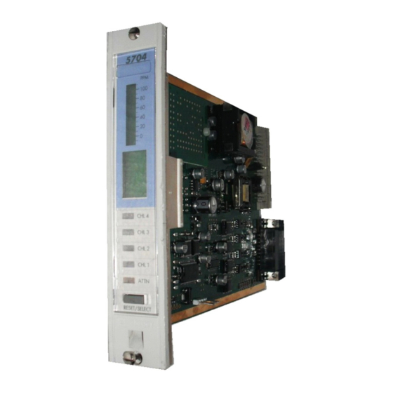
CHAPTER 2 - SySTEM DESCRIPTION FOUR CHANNEl CONTROl CARDS General The 5704 Four Channel Control Card provides control, display and alarm facilities for up to four connected gas detectors. The front panel backlit display indicates the gas reading, channel status and channel number while LEDs are used for alarms. -
Page 23: Analogue Output Module
MAN0448_Issue 13_01-2010 5704 Control System 005704-M-5001 A03249 CHAPTER 2 - SySTEM DESCRIPTION Control Functions The Four Channel Control Card carries out the control functions for up to four loops of gas detection as follows: Provides the necessary voltages and currents to drive the connected sensors. -
Page 24: Physical Layout
MAN0448_Issue 13_01-2010 5704 Control System 005704-M-5001 A03249 CHAPTER 2 - SySTEM DESCRIPTION Physical layout The physical layout of the Four Channel Control Card is shown below. Analogue Output Modules, when fitted, plug into channel sockets as shown: LK1 fitted to pins 1 - 2 Identification Label 4 CHANNEl CONTROl CARD... -
Page 25: Quad Relay Interface Card And Relay Interface Assembly
MAN0448_Issue 13_01-2010 5704 Control System 005704-M-5001 A03249 CHAPTER 2 - SySTEM DESCRIPTION QUAD RElAy INTERFACE CARD AND RElAy INTERFACE ASSEMBly General The Quad Relay Interface Card provides the interface between a Four Channel Control Card and the field wiring. An Expansion Relay Card can also be factory fitted to the Quad Relay Interface Card and the resultant assembly is then known as the Relay Interface Assembly. - Page 26 MAN0448_Issue 13_01-2010 5704 Control System 005704-M-5001 A03249 CHAPTER 2 - SySTEM DESCRIPTION 5.2.2 Quad Relay Card Rear Access Connections Rl1-NC (Master Fault) Rl1-NO (Master Fault) Slot location label Rl1-COM (Master Fault) 3 Rl2-COM (Master A1) Rl2-NC (Master A1) Rl2-NO (Master A1)
- Page 27 MAN0448_Issue 13_01-2010 5704 Control System 005704-M-5001 A03249 CHAPTER 2 - SySTEM DESCRIPTION 5.2.3 Quad Relay Card Front Access Connections label for User Terminal Reference 0V Input +24V Input Remote Inhibit Remote Reset Analogue CH4 Analogue CH3 Analogue CH2 Analogue CH1...
-
Page 28: Relay Interface Assembly
MAN0448_Issue 13_01-2010 5704 Control System 005704-M-5001 A03249 CHAPTER 2 - SySTEM DESCRIPTION Relay Interface Assembly (Part Number 05704-A-0131) 5.3.1 General The following diagrams show the Expansion Relay Card fitted to the Quad Interface Relay Card to form a Relay Interface Assembly: Rear Access Front Access Front Access Front View Front View... - Page 29 MAN0448_Issue 13_01-2010 5704 Control System 005704-M-5001 A03249 CHAPTER 2 - SySTEM DESCRIPTION 5.3.2 Relay Interface Assembly Rear Access Connections Expansion Quad Relay Card Card Slot location label QUAD RElAy CARD ExPANSION CARD left Right left Right Rl1-NC (Master Fault) Rl1-NO (Master Fault)
- Page 30 MAN0448_Issue 13_01-2010 5704 Control System 005704-M-5001 A03249 CHAPTER 2 - SySTEM DESCRIPTION 5.3.3 Relay Interface Assembly Front Access Connections Quad Relay Expansion Card Card label for User Terminal Reference ExPANSION CARD QUAD RElAy CARD left Right left Right 36 Not Used...
-
Page 31: Expansion Relay Card
MAN0448_Issue 13_01-2010 5704 Control System 005704-M-5001 A03249 CHAPTER 2 - SySTEM DESCRIPTION Expansion Relay Card The Expansion Relay Card provides relay expansion for a Four Channel Control Card and the Quad Relay Interface Card. The Expansion Relay Card is connected to the Quad Relay Interface Card and provides 12 additional relays, eight of which are single pole changeover and four are single pole single throw. The relays can be configured for A1, A2,... -
Page 32: Engineering Card
MAN0448_Issue 13_01-2010 5704 Control System 005704-M-5001 A03249 CHAPTER 2 - SySTEM DESCRIPTION ENGINEERING CARD PART NUMBER (05701-A-0361) The Engineering Card is used on a System 57 rack to provide a common interface that enables the user to perform all the required functions to commission and operate each fitted control card. - Page 33 MAN0448_Issue 13_01-2010 5704 Control System 005704-M-5001 A03249 CHAPTER 2 - SySTEM DESCRIPTION One of four optional modules may be fitted to the Engineering Card: Master Alarm Update Module This facility provides an indication when a new alarm occurs on any channel in the rack, even if a previous alarm condition already exists.
-
Page 34: Dc Input Card
To prevent excessive current flow along the rack backplane in installations where more than eight 5704 Catalytic Cards are used, it is recommended that the Control Cards are powered via their associated Quad Relay Interface Card and the DC Input Card used to power the Engineering Card only. -
Page 35: Dc Input Card Rear Access Connections
PSU 1 and PSU 2 (and AUx 1 and AUx 2) must be compatible with parallel connection. Note: For 5704 systems with more than eight catalytic control cards, it is recommended that the dc power is connected direct to each channels' Quad Relay Card. -
Page 36: Dc Input Card Front Access Connections
PSU 1 and PSU 2 (and AUx 1 and AUx 2) must be compatible with parallel connection. Note: For 5704 systems with more than eight catalytic control cards, it is recommended that the dc power is connected direct to each channels' Quad Relay Card. -
Page 37: Ac To Dc Power Supply Units
MAN0448_Issue 13_01-2010 5704 Control System 005704-M-5001 A03249 CHAPTER 2 - SySTEM DESCRIPTION AC TO DC POWER SUPPly UNITS Types of Power Supply Unit There are two types of AC to DC power supply units: 8-Way AC to DC Power Supply Unit (Part Number 05701-A-0406) A 1U high half width 19 inch rack mounted unit that contains a single 50W Switched Mode AC to DC Power Supply Module. -
Page 38: 8-Way Ac To Dc Power Supply Unit Layout
MAN0448_Issue 13_01-2010 5704 Control System 005704-M-5001 A03249 CHAPTER 2 - SySTEM DESCRIPTION 8-Way AC to DC Power Supply Unit layout Front View Top View Rear View Input ac 24V dc Output Voltage. Supply Voltage 50W per Fitted Module 16-Way AC to DC Power Supply Unit layout... -
Page 39: Sub-Unit Layout
MAN0448_Issue 13_01-2010 5704 Control System 005704-M-5001 A03249 CHAPTER 2 - SySTEM DESCRIPTION 50W Sub-Unit layout The 50W Sub-unit is fitted with a single 50W Switched Mode AC to DC Power Supply Module as shown below: Top View 50W Switched Mode (with cover AC to DC Power removed) Supply Module This type of unit is identified on the identification label as follows: Indicates 50W Unit POWER SUPPLY UNIT 05700-A-0405 Iss. -
Page 40: Front Panel Blanking Panel
MAN0448_Issue 13_01-2010 5704 Control System 005704-M-5001 A03249 CHAPTER 2 - SySTEM DESCRIPTION FRONT PANEl BlANKING PANEl Matching blank front panels are available for fitting to the rack in all unused control card spaces. 2-26... - Page 41 MAN0448_Issue 13_01-2010 5704 Control System 005704-M-5001 A03249 CHAPTER 2 - SySTEM DESCRIPTION USER NOTES 2-27...
- Page 42 MAN0448_Issue 13_2010 5704 Control System 005704-M-5001 A03249 CHAPTER 3 CONTROlS AND FACIlITIES 5704 SERIES CONTROl SySTEM CHAPTER 3 CONTROlS AND FACIlITIES...
- Page 43 MAN0448_Issue 13_2010 5704 Control System 005704-M-5001 A03249 CHAPTER 3 CONTROlS AND FACIlITIES CONTENTS Section Page Introduction Four Channel Control Card 2.1 General 2.2 Liquid Crystal Display 2.3 Status LEDs 3-11 2.4 Reset/Select Push-button 3-14 2.5 Extraction Slot 3-15 2.6 Display Label and Cover...
-
Page 44: Introduction
005704-M-5001 A03249 CHAPTER 3 CONTROlS AND FACIlITIES INTRODUCTION The 5704 Series Control System is equipped to provide the operational and engineering facilities necessary to fully maintain a system of gas detection equipment. Each control card within a rack system displays a sensor reading, alarm status condition and channel reading number. - Page 45 MAN0448_Issue 13_2010 5704 Control System 005704-M-5001 A03249 CHAPTER 3 CONTROlS AND FACIlITIES LTEL Alarm (Long Term Exposure Limit). The LTEL alarm will be activated when the time weighted average concentration of a toxic gas, usually averaged over 8 hours, crosses a preconfigured threshold. The control card alarm LED, associated...
- Page 46 MAN0448_Issue 13_2010 5704 Control System 005704-M-5001 A03249 CHAPTER 3 CONTROlS AND FACIlITIES Voted Alarm* A voted alarm is caused by the simultaneous presence of an identical alarm on more than one control channel within a preconfigured group. The relevant LED (A1, A2, A3, Fault, Inhibit) will illuminate as described in Section 2.3.1 on the control cards with the alarm...
- Page 47 MAN0448_Issue 13_2010 5704 Control System 005704-M-5001 A03249 CHAPTER 3 CONTROlS AND FACIlITIES Rising Alarm A rising alarm is caused by a rising level of the parameter being measured crossing a preconfigured threshold. This will also cause the associated alarm LED to illuminate as described in Section 2.3.1. Falling Alarm A falling alarm is caused by a falling level of the parameter being measured crossing a preconfigured threshold. This will also cause...
- Page 48 MAN0448_Issue 13_2010 5704 Control System 005704-M-5001 A03249 CHAPTER 3 CONTROlS AND FACIlITIES Time Delay Alarms The operation in response to alarm events of certain relays may be modified by applying a delay function to the relays. Time delay functions are available to delay the activation of a relay for a short period after an alarm event occurs and/or to maintain relay activation for a period after the alarm event has cleared.
-
Page 49: Four Channel Control Card
MAN0448_Issue 13_2010 5704 Control System 005704-M-5001 A03249 CHAPTER 3 CONTROlS AND FACIlITIES FOUR CHANNEl CONTROl CARD General The Four Channel Control Card provides the necessary power supplies to the associated sensors and conditions the incoming sensor signals. The received sensor... - Page 50 MAN0448_Issue 13_2010 5704 Control System 005704-M-5001 A03249 CHAPTER 3 CONTROlS AND FACIlITIES The method of displaying each channels information can be selected from one of the following: Automatic sequencing. Highest reading. 5704 Combination of automatic sequencing and highest reading. Manually selected.
- Page 51 MAN0448_Issue 13_2010 5704 Control System 005704-M-5001 A03249 CHAPTER 3 CONTROlS AND FACIlITIES The default mode of operation is a rising solid bar current gas reading display with a peak reading facility, and with a combination of automatic sequencing between channels and highest reading.
-
Page 52: Status Leds
MAN0448_Issue 13_2010 5704 Control System 005704-M-5001 A03249 CHAPTER 3 CONTROlS AND FACIlITIES Status lEDS 2.3.1 CHl (Channel) lEDs The four CHL alarm LEDs on the front panel of the control card provide multi status indications for each channel. These LEDs indicate as... - Page 53 MAN0448_Issue 13_2010 5704 Control System 005704-M-5001 A03249 CHAPTER 3 CONTROlS AND FACIlITIES A1 AlARM - Flashing Red CHL LED The A1 channel alarm condition is shown by the associated CHL LED flashing red once per period as shown below: //////////// //////////// //////////// //////////// //////////// //////////// //////////// //////////// //////////// 0.8s...
- Page 54 MAN0448_Issue 13_2010 5704 Control System 005704-M-5001 A03249 CHAPTER 3 CONTROlS AND FACIlITIES Special Alarm (STEl and lTEl) Slow Flashing Red CHL LED. ///////////////////////////////////// ///////////////////////////////////// ///////////////////////////////////// ///////////////////////////////////// ///////////////////////////////////// ///////////////////////////////////// ///////////////////////////////////// ///////////////////////////////////// 1 second 1 second 1 second 1 second A slow flashing red CHL LED indicates that a STEL or LTEL alarm level has been exceeded.
-
Page 55: Reset/Select Push-Button
MAN0448_Issue 13_2010 5704 Control System 005704-M-5001 A03249 CHAPTER 3 CONTROlS AND FACIlITIES AlARM TEST Steady Amber ATTN LED //////////////////////////////////////////////////////////////////////////////////////////////////////////////////////////////////////////////////////////////////////////// //////////////////////////////////////////////////////////////////////////////////////////////////////////////////////////////////////////////////////////////////////////// //////////////////////////////////////////////////////////////////////////////////////////////////////////////////////////////////////////////////////////////////////////// 1 second 1 second A steady amber ATTN LED indicates control card is in the alarm test mode. Reset/Select Push-button... -
Page 56: Extraction Slot
MAN0448_Issue 13_2010 5704 Control System 005704-M-5001 A03249 CHAPTER 3 CONTROlS AND FACIlITIES Channel Deselect The RESET/SElECT push-button, when pressed momentarily while a control card is selected, deselects the control card from the Engineering Card functions. Note: The control card may also be deselected by pressing the key. - Page 57 MAN0448_Issue 13_2010 5704 Control System 005704-M-5001 A03249 CHAPTER 3 CONTROlS AND FACIlITIES Extraction Hole The perspex cover is removed by first removing the control card from 5704 the rack and then locating a small hole on the inside of the front panel just above the LCD display. A blunt object, such as a screwdriver, is then pushed through the hole to unclip the perspex cover.
-
Page 58: Engineering Card
MAN0448_Issue 13_2010 5704 Control System 005704-M-5001 A03249 CHAPTER 3 CONTROlS AND FACIlITIES ENGINEERING CARD General The Engineering Card provides facilities to allow each control card channel to be interrogated and to allow normal maintenance functions such as calibration to be carried out. It also acts as a connecting point for the engineering interface software which allows each card to be configured. -
Page 59: Engineering Push-Buttons
MAN0448_Issue 13_2010 5704 Control System 005704-M-5001 A03249 CHAPTER 3 CONTROlS AND FACIlITIES Flashing: Indicates that a control card has been withdrawn from the rack, there is a communications error or that an external PC running the engineering interface software is communicating with the control cards. - Page 60 MAN0448_Issue 13_2010 5704 Control System 005704-M-5001 A03249 CHAPTER 3 CONTROlS AND FACIlITIES 3.3.6 Reject Push-button ( ) When operated during any of the engineers functions and providing the accept ( ) push-button has not been operated, the reject push-button ( ) cancels adjustments that have been made. This push-button is also used to deselect a selected function and for manual channel display selections.
- Page 61 MAN0448_Issue 13_2010 5704 Control System 005704-M-5001 A03249 CHAPTER 3 CONTROlS AND FACIlITIES 3.3.11 SPAN Push-button The SPAN push-button can only be used when the Engineering Key is fitted to the Engineering Card and is used to calibrate the span point of the selected control card channel. 3.3.12 1ST SPAN Push-button The 1ST SPAN push-button can only be used when the Engineering...
-
Page 62: Engineering Serial Port
MAN0448_Issue 13_2010 5704 Control System 005704-M-5001 A03249 CHAPTER 3 CONTROlS AND FACIlITIES Engineering Serial Port The Engineering Serial Port is a miniature DIN socket which provides three functions: Connection point for the Engineering Key to unlock the engineers functions. Connection point for the External Engineering Interface which allows each control card to be configured by an external PC running the engineering interface configuration software. - Page 63 MAN0448_Issue 13_2010 5704 Control System 005704-M-5001 A03249 CHAPTER 3 CONTROlS AND FACIlITIES 3-22...
- Page 64 MAN0448_Issue 13_01-2010 5704 Control System 005704-M-5001 A03249 CHAPTER 4 - INSTAllATION INSTRUCTIONS 5704 SERIES CONTROl SySTEM CHAPTER 4 INSTAllATION INSTRUCTIONS...
- Page 65 In addition, appropriate local or national regulations shall be used.” IMPORTANT NOTICES 1. Honeywell Analytics Limited can take no responsibility for installation and/or use of its equipment if this is not done in accordance with the appropriate issue and/or amendment of the manual.
- Page 66 MAN0448_Issue 13_01-2010 5704 Control System 005704-M-5001 A03249 CHAPTER 4 - INSTAllATION INSTRUCTIONS CONTENTS Section Page INTRODUCTION UNPACKING LOCATION CABLING POWER REQUIREMENTS VENTILATION PRELIMINARIES CABINET INSTALLATION 4-10 PANEL INSTALLATION 4-12 10. RACK INSTALLATION 4-14 11. SENSOR INSTALLATION 4-15 11.1 General 4-15 11.2 Sensor Line Resistance...
- Page 67 MAN0448_Issue 13_01-2010 5704 Control System 005704-M-5001 A03249 CHAPTER 4 - INSTAllATION INSTRUCTIONS 15.1 General 4-49 15.2 Individually Powered Control Cards 4-50 16. AC TO DC POWER SUPPLY UNIT CONNECTIONS 4-51 17. UPGRADING THE AC TO DC POWER SUPPLY UNITS 4-53 17.1 General...
-
Page 68: Introduction
MAN0448_Issue 13_01-2010 5704 Control System 005704-M-5001 A03249 CHAPTER 4 - INSTAllATION INSTRUCTIONS INTRODUCTION A summary of the System 57 controller installation procedures is shown below: Unpack and check the equipment. Identify a suitable location and check the cabling requirements. Confirm the power supply requirements. -
Page 69: Location
MAN0448_Issue 13_01-2010 5704 Control System 005704-M-5001 A03249 CHAPTER 4 - INSTAllATION INSTRUCTIONS Check the contents for transit damage and against the packing note for deficiencies. Locate the configuration sheet supplied with the unit and confirm that each channel card type and settings are compatible with the proposed sensors. lOCATION The control system must be installed in a safe area such as a control or equipment room. -
Page 70: Cabling
MAN0448_Issue 13_01-2010 5704 Control System 005704-M-5001 A03249 CHAPTER 4 - INSTAllATION INSTRUCTIONS CABlING The field terminals on the Quad Relay Interface and Relay Interface Assembly accept single or multi-stranded wire up to 2.5mm˝ (14 AWG). Cables should be routed carefully to avoid physical and environmental hazards such as mechanical stress and high temperatures. Sensor wiring should consist of a cable with an earthed outer shield and should be routed away from sources of interference such as ac power cables, motors, machinery etc. All sensor cabling is subject to a... - Page 71 MAN0448_Issue 13_01-2010 5704 Control System 005704-M-5001 A03249 CHAPTER 4 - INSTAllATION INSTRUCTIONS Table 1 Power Budget Calculation Sheet To calculate the power requirement: Enter the number of devices of each type used in the system in column B. Multiply by the unit power shown in column C.
-
Page 72: Ventilation
VENTIlATION The 5704 Control System provides the facility for a large number of channels in a very small space. In heavily populated racks, especially those with many catalytic input control cards or relays configured for... -
Page 73: Cabinet Installation
MAN0448_Issue 13_01-2010 5704 Control System 005704-M-5001 A03249 CHAPTER 4 - INSTAllATION INSTRUCTIONS CABINET INSTAllATION Two cabinets are available, an 8-way to accommodate the 8-way front access rack and a 16-way to accommodate the 16-way front access rack. The cabinet must be secured to a wall, or other suitable vertical surface,... - Page 74 MAN0448_Issue 13_01-2010 5704 Control System 005704-M-5001 A03249 CHAPTER 4 - INSTAllATION INSTRUCTIONS Cabinet Dimensions: 8 way 337 16 way 540 All dimension shown in mm. Wall Mounting Bracket Hole locations Cabinet Mounting Brackets 8 way 16 way All dimension shown in mm.
-
Page 75: Panel Installation
MAN0448_Issue 13_01-2010 5704 Control System 005704-M-5001 A03249 CHAPTER 4 - INSTAllATION INSTRUCTIONS Eight Card Cabinet Installation Blanking Panel 8-Way AC to DC Power Supply Unit Control Cards Engineering Card Interface/Relay DC Input Card Cards Accessory Plate (suitable for mounting DIN rails, circuit breakers, relays, etc.) - Page 76 MAN0448_Issue 13_01-2010 5704 Control System 005704-M-5001 A03249 CHAPTER 4 - INSTAllATION INSTRUCTIONS (holes 6mm diameter) (holes 6mm diameter) Rack Table of Sizes (mm) Rack Assembly Depth 8 Way Rear Access 279.4 261.9 57.0 37.8 132.5 287.6 8 Way Front Access 279.4 261.9 190.5...
-
Page 77: Rack Installation
MAN0448_Issue 13_01-2010 5704 Control System 005704-M-5001 A03249 CHAPTER 4 - INSTAllATION INSTRUCTIONS 43.6 31.8 AC to DC PSU Table of Sizes (mm) PSU Assembly Clearance Width Height Depth 8 Way 279.4 261.9 16 Way 482.6 465.1 Insert the rack into the aperture and secure using M6, or similar bolts, through the four mounting holes located upon the front flange plates. -
Page 78: Sensor Installation
MAN0448_Issue 13_01-2010 5704 Control System 005704-M-5001 A03249 CHAPTER 4 - INSTAllATION INSTRUCTIONS Insert the rack into the 19" Mounting Frame and secure using M6 or similar bolts through the four mounting holes located on the front flange plates. Ensure adequate support at the rear of rear access racks. -
Page 79: Sensor Line Resistance
MAN0448_Issue 13_01-2010 5704 Control System 005704-M-5001 A03249 CHAPTER 4 - INSTAllATION INSTRUCTIONS 11.2 Sensor line Resistance Sensors should be located such that the line resistance of cable does not exceed the maximum permitted. The table below gives a quick guide... -
Page 80: Cable Resistance Guide
MAN0448_Issue 13_01-2010 5704 Control System 005704-M-5001 A03249 CHAPTER 4 - INSTAllATION INSTRUCTIONS The following sections outline how to calculate the maximum line resistance for catalytic sensors, loop powered sensors and transmitters powered from the System 57. See Section 11.3 for a guide on cable selection. -
Page 81: 20Ma Loop Powered Sensors
MAN0448_Issue 13_01-2010 5704 Control System 005704-M-5001 A03249 CHAPTER 4 - INSTAllATION INSTRUCTIONS 11.5 4 - 20mA loop Powered Sensors: The maximum line resistance of cabling for a 4 - 20mA loop powered sensor varies with the voltage drive requirements of the type of sensor installed. It is also subject to a 24V maximum loop drive voltage. -
Page 82: Sensor Connections
MAN0448_Issue 13_01-2010 5704 Control System 005704-M-5001 A03249 CHAPTER 4 - INSTAllATION INSTRUCTIONS SENSOR CONNECTIONS 12.1 General WARNING Incorrect connection of the sensor wires may cause damage to both the sensor and System 57. CAUTION The sensors connections must always be made with the System 57 unit in an unpowered state. - Page 83 MAN0448_Issue 13_01-2010 5704 Control System 005704-M-5001 A03249 CHAPTER 4 - INSTAllATION INSTRUCTIONS The sensor cable screen or steel wire armour (or braid), as appropriate, should be connected to the system (protective) earth. This can be achieved where the cable enters the cabinet by using a metal cable gland, or by other suitable means, and avoiding any screen 'tails' within the cabinet.
- Page 84 MAN0448_Issue 13_01-2010 5704 Control System 005704-M-5001 A03249 CHAPTER 4 - INSTAllATION INSTRUCTIONS Quad Relay Interface Card 05704-A-0121 Junction Box Terminal Junction Block Separate Screen Sheath (If Fitted) Brown White Blue Green/yellow Screened/Armoured Cable Protective Earth Terminal Earth 780 Series 910 704/705...
- Page 85 MAN0448_Issue 13_01-2010 5704 Control System 005704-M-5001 A03249 CHAPTER 4 - INSTAllATION INSTRUCTIONS Notes: 1. Where a sensor is earthed locally, either to an Earth Stud or through the sensor casing or mounting, to avoid earth loops the screen sheath of the cable should only be connected at one end.
-
Page 86: 12.3 4 - 20Ma Loop Powered Sensor Connections
MAN0448_Issue 13_01-2010 5704 Control System 005704-M-5001 A03249 CHAPTER 4 - INSTAllATION INSTRUCTIONS 12.3 4 - 20mA loop Powered Sensor Connections Loop powered sensors require a two wire connection and the sensor documentation will indicate the positive and negative loop connections, usually brown and blue respectively. - Page 87 MAN0448_Issue 13_01-2010 5704 Control System 005704-M-5001 A03249 CHAPTER 4 - INSTAllATION INSTRUCTIONS Quad Relay Interface Card 05704-A-0121 Junction Box Terminal Block Junction Arrows Indicate Direction of loop Current Flow Brown Blue Green/yellow Screened Cable Protective Earth Terminal 811, 911 ECC,...
-
Page 88: 12.4 4 - 20Ma Transmitter Connections
MAN0448_Issue 13_01-2010 5704 Control System 005704-M-5001 A03249 CHAPTER 4 - INSTAllATION INSTRUCTIONS 12.4 4 - 20mA Transmitter Connections Transmitters require either three or four wire connections and the sensor documentation will indicate the 0V and +24V power connections and the positive and negative loop connections. - Page 89 MAN0448_Issue 13_01-2010 5704 Control System 005704-M-5001 A03249 CHAPTER 4 - INSTAllATION INSTRUCTIONS Opus/Lifeline II Transmitter Quad Relay Interface Card 05704-A-0121 Arrows Indicate Direction of Loop +24V* Current Flow Screen to cable gland Screened Cable Protective Earth Cabinet * 24V supply may be obtained...
- Page 90 MAN0448_Issue 13_01-2010 5704 Control System 005704-M-5001 A03249 CHAPTER 4 - INSTAllATION INSTRUCTIONS Quad Relay Interface Card 05704-A-0121 Opus/Lifeline II Transmitter Arrows Indicate Direction of Loop +24V* Current Flow Cabinet Screen to cable gland Screened Cable Protective * 24V supply may be obtained...
- Page 91 MAN0448_Issue 13_01-2010 5704 Control System 005704-M-5001 A03249 CHAPTER 4 - INSTAllATION INSTRUCTIONS Apex Transmitter Quad Relay Interface Card 05704-A-0121 Arrows Indicate Direction of loop Current Flow +24V* +24V 4 - 20mA(-) Cabinet Screened Cable Protective Earth Apex link Settings: (Comms...
- Page 92 MAN0448_Issue 13_01-2010 5704 Control System 005704-M-5001 A03249 CHAPTER 4 - INSTAllATION INSTRUCTIONS Quad Relay Interface Card Apex Transmitter 05704-A-0121 Arrows Indicate Direction of loop +24V* Current Flow +24V 4 - 20mA(-) 4 - 20mA(+) Cabinet Screened Cable Protective Earth Apex link...
- Page 93 MAN0448_Issue 13_01-2010 5704 Control System 005704-M-5001 A03249 CHAPTER 4 - INSTAllATION INSTRUCTIONS Quad Relay Interface Card 05704-A-0121 Series 2000 Flammable Arrows Indicate Direction of loop +24V* Current Flow +24V 4 - 20mA (-) Link fitted for Screened Cable Transmitter Source...
- Page 94 MAN0448_Issue 13_01-2010 5704 Control System 005704-M-5001 A03249 CHAPTER 4 - INSTAllATION INSTRUCTIONS Quad Relay Interface Card 05704-A-0121 Connections using a Searchline Excel Receiver DVC100 Junction Box Current Source Field Connections Cabinet Arrows Indicate Direction of Loop BLUE Current Flow +24V*...
- Page 95 MAN0448_Issue 13_01-2010 5704 Control System 005704-M-5001 A03249 CHAPTER 4 - INSTAllATION INSTRUCTIONS Notes: 1. Where a sensor is earthed locally, either to an Earth Stud or through the sensor casing or mounting, to avoid earth loops the screen sheath of the cable should only be connected at one end.
- Page 96 MAN0448_Issue 13_01-2010 5704 Control System 005704-M-5001 A03249 CHAPTER 4 - INSTAllATION INSTRUCTIONS Notes: 1. Where a sensor is earthed locally, either to an Earth Stud or through the sensor casing or mounting, to avoid earth loops the screen sheath of the cable should only be connected at one end.
- Page 97 MAN0448_Issue 13_01-2010 5704 Control System 005704-M-5001 A03249 CHAPTER 4 - INSTAllATION INSTRUCTIONS Quad Relay Interface Card Terminal 05704-A-0121 Block Junction Searchpoint Optima (Configured for current Arrows Indicate source using hybrid Direction of loop module 04200-A-0146) Current Flow +24V* SHC1 +24V...
- Page 98 MAN0448_Issue 13_01-2010 5704 Control System 005704-M-5001 A03249 CHAPTER 4 - INSTAllATION INSTRUCTIONS Quad Relay Interface Card Terminal 05704-A-0121 Block Junction Searchpoint Optima Plus Arrows Indicate Configured for current Direction of loop source Current Flow +24V* SHC1 +24V 4 - 20mA (-)
- Page 99 MAN0448_Issue 13_01-2010 5704 Control System 005704-M-5001 A03249 CHAPTER 4 - INSTAllATION INSTRUCTIONS Quad Relay Interface Card 05704-A-0121 Arrows Indicate Direction of loop Current Flow Digi Series +24V* +24V 4 - 20mA(+) See Table for Cabinet Sensor Wiring Screened Cable * 24V supply may be obtained...
- Page 100 MAN0448_Issue 13_01-2010 5704 Control System 005704-M-5001 A03249 CHAPTER 4 - INSTAllATION INSTRUCTIONS Quad Relay Interface Card 05704-A-0121 Arrows Indicate Direction of loop Digi Series +24V* Current Flow +24V 4 - 20mA(-) 4 - 20mA(+) Cabinet See Table for Sensor Wiring...
- Page 101 MAN0448_Issue 13_01-2010 5704 Control System 005704-M-5001 A03249 CHAPTER 4 - INSTAllATION INSTRUCTIONS Quad Relay Interface Card 05704-A-0121 Series 2000 Ul Arrows Indicate Sensor Direction of loop Terminal Block Cabinet Current Flow Barrier Safety Ground +24V +24V links 4 - 20mA (+)
- Page 102 MAN0448_Issue 13_01-2010 5704 Control System 005704-M-5001 A03249 CHAPTER 4 - INSTAllATION INSTRUCTIONS 12.5 IS Transmitter Connections If the measuring resistance is in the negative supply line, a double safety barrier must be used. Quad Relay Interface Card IS Series 2000...
- Page 103 MAN0448_Issue 13_01-2010 5704 Control System 005704-M-5001 A03249 CHAPTER 4 - INSTAllATION INSTRUCTIONS If the measuring resistance is in the negative supply line, a double safety barrier must be used. Note 1: *To ensure that the input circuit is properly referred to the safety barrier it is necessary to connect the isolated 0V to the barrier ground.
-
Page 104: Output Connections
De-energised and Energised Relays Showing Contact Positions The alarm relays may be configured for either normally de-energised or normally energised operation. Check the configuration sheet supplied with the system to determine the operating mode of the relays on each channel. The energisation mode of the relays can be reconfigured easily using a computer attached to the Engineering Port. Contact Honeywell Analytics or your local agent for more information. 4-41... -
Page 105: 13.2 Analogue Output
MAN0448_Issue 13_01-2010 5704 Control System 005704-M-5001 A03249 CHAPTER 4 - INSTAllATION INSTRUCTIONS 13.2 Analogue Output Analogue Output Modules, when fitted, plug into the Four Channel Control Card as shown below: Plug-in Sockets for Analogue Output Modules: 04200-A-0145 Sink 04200-A-0146 Source... - Page 106 The operating mode can be reconfigured easily using a computer attached to the Engineering Port. Contact Honeywell Analytics or your local agent for more information. Note: With software versions prior to 1V6, the analogue output signal may not properly reflect the sensor signal when the sensor signal is outside the normal measuring range.
- Page 107 MAN0448_Issue 13_01-2010 5704 Control System 005704-M-5001 A03249 CHAPTER 4 - INSTAllATION INSTRUCTIONS Channel Analogue Power Supply Output Quad Relay Interface Connections Quad Relay Interface Card 05704-A-0121 Four Channel Control Card Fitted with: Analogue Output Module (Source) 04200-A-0146 Programmable logic Controller...
- Page 108 MAN0448_Issue 13_01-2010 5704 Control System 005704-M-5001 A03249 CHAPTER 4 - INSTAllATION INSTRUCTIONS Quad Relay Interface Card 05704-A-0121 Four Channel Control Card Fitted with: Analogue Output Module (Sink) 04200-A-0145 +24V (18V to 40V) Anlogue 24V Current Sense Analogue Channel 1 Analogue 0V...
- Page 109 MAN0448_Issue 13_01-2010 5704 Control System 005704-M-5001 A03249 CHAPTER 4 - INSTAllATION INSTRUCTIONS Quad Relay Interface Card 05704-A-0121 Four Channel Control Card Fitted with: Analogue Output Module (Sink) 04200-A-0145 +24V (18V to 40V) Anlogue 24V Chart Recorder R = 100 Input...
-
Page 110: Remote Input Connections
Check the configuration sheet supplied with the system to determine the factory configured operating modes. The operating mode can be reconfigured easily using a computer attached to the Engineering Port. Contact Honeywell Analytics or your local agent for more information. The switching level of the remote input pins (when enabled) is approximately +2V with respect to the dc system 0V. The inputs require less than 5mA drive current and irrespective of configuration are internally pulled down to system 0V. - Page 111 MAN0448_Issue 13_01-2010 5704 Control System 005704-M-5001 A03249 CHAPTER 4 - INSTAllATION INSTRUCTIONS Four Channel Control Card Configured for active 05704-A-0145 4 - 20mA high remote inputs 05704-A-0144 Catalytic Quad Relay Interface Card 05704-A-0121 Normally Open Contact +24V (18V to 32V)
-
Page 112: Dc Power Connections
MAN0448_Issue 13_01-2010 5704 Control System 005704-M-5001 A03249 CHAPTER 4 - INSTAllATION INSTRUCTIONS DC POWER CONNECTIONS 15.1 General CAUTION The ratings of power supplies should be checked by calculating a system power budget as outlined in Section 5. IMPORTANT The System 57 must be earthed DC power is connected to the System 57 via the DC Input Card terminal block TB1 and via the Quad Relay Interface Cards. -
Page 113: 15.2 Individually Powered Control Cards
MAN0448_Issue 13_01-2010 5704 Control System 005704-M-5001 A03249 CHAPTER 4 - INSTAllATION INSTRUCTIONS 15.2 Individually Powered Control Cards Notes: 1. In individually powered control systems a DC connection is still required to the DC Input Card in order to provide power to the Engineering Card. -
Page 114: Ac To Dc Power Supply Unit Connections
The input supply to the AC to DC Power Supply Unit may be: an ac supply of 85V to 264V at 47Hz to 440Hz. a dc supply of 110V to 340V (Refer to Honeywell Analytics for information on dc supplies). The supply must be fused at 6A maximum at the supply source. eg. At the distribution panel. - Page 115 MAN0448_Issue 13_01-2010 5704 Control System 005704-M-5001 A03249 CHAPTER 4 - INSTAllATION INSTRUCTIONS AC to DC PSU AC to DC PSU 50W Sub-Unit 50W Sub-Unit Earth Earth System AC Input Stud Stud Earth Supply Brown Blue Green/yellow DC Input Card Brown...
-
Page 116: Upgrading The Ac To Dc Power Supply Units
MAN0448_Issue 13_01-2010 5704 Control System 005704-M-5001 A03249 CHAPTER 4 - INSTAllATION INSTRUCTIONS UPGRADING THE AC TO DC POWER SUPPly UNITS WARNING High voltages exist within the AC to DC Power Supply Unit. Disconnect from the ac supply for a period of at least five minutes before removing the top cover and carrying out any maintenance or upgrade operation. - Page 117 MAN0448_Issue 13_01-2010 5704 Control System 005704-M-5001 A03249 CHAPTER 4 - INSTAllATION INSTRUCTIONS Front View 50W Switched Mode AC to DC Power Supply Module Top View 50W Switched Mode AC to DC Power Supply Module Rear View Input AC 24V 100W DC...
- Page 118 MAN0448_Issue 13_01-2010 5704 Control System 005704-M-5001 A03249 CHAPTER 4 - INSTAllATION INSTRUCTIONS Front View 50W Switched Mode AC to DC Power Supply Module Top View 50W Switched Mode AC to DC Power Supply Module Rear View Input AC 24V 100W DC...
-
Page 119: 8-Way And 16-Way Ac To Dc Power Supply Unit Upgrade To 100W
MAN0448_Issue 13_01-2010 5704 Control System 005704-M-5001 A03249 CHAPTER 4 - INSTAllATION INSTRUCTIONS Front View 50W Switched Mode AC to DC 50W Switched Mode AC to DC Power Supply Module Power Supply Module Top View 50W Switched Mode AC to DC... -
Page 120: 16-Way Ac To Dc Power Supply Unit Upgrade To 150W Or 200W
MAN0448_Issue 13_01-2010 5704 Control System 005704-M-5001 A03249 CHAPTER 4 - INSTAllATION INSTRUCTIONS (5) Insert the module, with the same orientation as the already fitted module, into the vacant position inside the 50W Sub Unit and secure using the washers and long nuts retained in Step (3). Connect the 50W Sub Unit second ac input and 24V dc output cable... - Page 121 MAN0448_Issue 13_01-2010 5704 Control System 005704-M-5001 A03249 CHAPTER 4 - INSTAllATION INSTRUCTIONS USER NOTES 4-58...
- Page 122 MAN0448_Issue 13_ 01-2010 5704 Control System 005704-M-5001 A03249 CHAPTER 5 - COMMISSIONING AND MAINTENANCE INSTRUCTIONS 5704 SERIES CONTROl SySTEM CHAPTER 5 COMMISSIONING AND MAINTENANCE INSTRUCTIONS...
- Page 123 MAN0448_Issue 13_ 01-2010 5704 Control System 005704-M-5001 A03249 CHAPTER 5 - COMMISSIONING AND MAINTENANCE INSTRUCTIONS CONTENTS Section Page General Start Up Procedure Calibration Maintenance Error Codes 5.1 General 5.2 Start-up Hardware Faults 5.3 Run Time Errors 5-10 5.4 Calibration Errors 5-13 5.5 System Errors...
-
Page 124: General
MAN0448_Issue 13_ 01-2010 5704 Control System 005704-M-5001 A03249 CHAPTER 5 - COMMISSIONING AND MAINTENANCE INSTRUCTIONS WARNING High ac mains voltages may be present at the system power supply unit and at the relay terminals of the interface cards. Appropriate safety precautions must be taken when commissioning or servicing the system. - Page 125 MAN0448_Issue 13_ 01-2010 5704 Control System 005704-M-5001 A03249 CHAPTER 5 - COMMISSIONING AND MAINTENANCE INSTRUCTIONS Reconnect the terminal block TB1 to the DC Input Card. Switch on the system power supply. Check that a voltage of between 18V and 32V dc still exists at the terminal block TB1.
-
Page 126: Calibration
MAN0448_Issue 13_ 01-2010 5704 Control System 005704-M-5001 A03249 CHAPTER 5 - COMMISSIONING AND MAINTENANCE INSTRUCTIONS CAlIBRATION Leave the connected sensors to stabilise for a period as specified in the sensor manual. Adjust the sensor head current of catalytic sensors as described in Chapter 7 Section 7 to the required value as indicated in the sensor operating instructions. -
Page 127: Maintenance
MAN0448_Issue 13_ 01-2010 5704 Control System 005704-M-5001 A03249 CHAPTER 5 - COMMISSIONING AND MAINTENANCE INSTRUCTIONS MAINTENANCE To ensure that the system functions correctly, maintenance should be carried out on a regular basis as dictated by the site regulations and instructions for the type of sensor being used. For installations in the EU, EN 60079-29-2 should be followed.”... -
Page 128: Error Codes
MAN0448_Issue 13_ 01-2010 5704 Control System 005704-M-5001 A03249 CHAPTER 5 - COMMISSIONING AND MAINTENANCE INSTRUCTIONS ERROR CODES General Operating errors within the system are indicated on the LCD message display as an error code. The error codes used and their meaning are listed in the following sections. - Page 129 MAN0448_Issue 13_ 01-2010 5704 Control System 005704-M-5001 A03249 CHAPTER 5 - COMMISSIONING AND MAINTENANCE INSTRUCTIONS Self Test Faults Note: In addition to some of the following fault codes that may be displayed, the control card ATTN LED will flash one second on one second off should a hardware or software fault be detected on the control card.
- Page 130 MAN0448_Issue 13_ 01-2010 5704 Control System 005704-M-5001 A03249 CHAPTER 5 - COMMISSIONING AND MAINTENANCE INSTRUCTIONS Error Error Code Meaning Software Card Fault latch Code Version Status Signal No Vps. Active Vps is a voltage which is used to set the absolute value reference for the reading scaling factor.
-
Page 131: Run Time Errors
MAN0448_Issue 13_ 01-2010 5704 Control System 005704-M-5001 A03249 CHAPTER 5 - COMMISSIONING AND MAINTENANCE INSTRUCTIONS Run Time Errors Error Error Code Meaning Software Card Fault latch Code Version Status Signal Hardware Fault Active The hardware fault message is displayed if the channel card detects a fault in its operation or a fault with a sensor input. - Page 132 MAN0448_Issue 13_ 01-2010 5704 Control System 005704-M-5001 A03249 CHAPTER 5 - COMMISSIONING AND MAINTENANCE INSTRUCTIONS Error Error Code Meaning Software Card Fault latch Code Version Status Signal This allows cards to be moved to alternative slot locations for fault finding purposes.
- Page 133 MAN0448_Issue 13_ 01-2010 5704 Control System 005704-M-5001 A03249 CHAPTER 5 - COMMISSIONING AND MAINTENANCE INSTRUCTIONS Error Error Code Meaning Software Card Fault latch Code Version Status Signal The lifetime is calculated on the difference between the sensitivity measured during 1st...
-
Page 134: Calibration Errors
MAN0448_Issue 13_ 01-2010 5704 Control System 005704-M-5001 A03249 CHAPTER 5 - COMMISSIONING AND MAINTENANCE INSTRUCTIONS Error Error Code Meaning Software Card Fault latch Code Version Status Signal This provides a warning that the sensor is detecting a level of gas exceeding the set operating range of the channel. - Page 135 MAN0448_Issue 13_ 01-2010 5704 Control System 005704-M-5001 A03249 CHAPTER 5 - COMMISSIONING AND MAINTENANCE INSTRUCTIONS Error Error Code Meaning Software Card Fault latch Code Version Status Signal Zero Signal Too Low The zero signal too low message is displayed during calibration when the sensor zero signal is below the pre-configured levels and a zero calibration can not be achieved.
- Page 136 MAN0448_Issue 13_ 01-2010 5704 Control System 005704-M-5001 A03249 CHAPTER 5 - COMMISSIONING AND MAINTENANCE INSTRUCTIONS Error Error Code Meaning Software Card Fault latch Code Version Status Signal This indicates that the output from the sensor is too low due to either: a.
-
Page 137: System Errors
MAN0448_Issue 13_ 01-2010 5704 Control System 005704-M-5001 A03249 CHAPTER 5 - COMMISSIONING AND MAINTENANCE INSTRUCTIONS System Errors Error Error Code Meaning Software Card Fault latch Code Version Status Signal Invalid Sub-Channel Active No Indicates a request has been received for an invalid sub-channel address. -
Page 138: Miscellaneous Errors
MAN0448_Issue 13_ 01-2010 5704 Control System 005704-M-5001 A03249 CHAPTER 5 - COMMISSIONING AND MAINTENANCE INSTRUCTIONS Error Error Code Meaning Software Card Fault latch Code Version Status Signal Active Yes Communications Error A participant in a complex alarm function hosted by this card has stopped communicating. -
Page 139: Fault Finding
MAN0448_Issue 13_ 01-2010 5704 Control System 005704-M-5001 A03249 CHAPTER 5 - COMMISSIONING AND MAINTENANCE INSTRUCTIONS FAUlT FINDING The following table provides a guide to diagnosing various conditions within the operation of System 57. Note: In addition to some of the following fault codes that may be... - Page 140 MAN0448_Issue 13_ 01-2010 5704 Control System 005704-M-5001 A03249 CHAPTER 5 - COMMISSIONING AND MAINTENANCE INSTRUCTIONS Action Fault Check the error code tables in An error message is Section 5 for explanation. displayed. A CHL LED indicates a fault Check the message display for condition by flashing amber an error code.
- Page 141 MAN0448_Issue 13_ 01-2010 5704 Control System 005704-M-5001 A03249 CHAPTER 5 - COMMISSIONING AND MAINTENANCE INSTRUCTIONS Fault Action There is no relay operation Check to see if the channel is in the and a CHL LED indicates inhibited condition and if necessary either: remove the inhibit.
- Page 142 MAN0448_Issue 13_01-2010 5704 Control System 005704-M-5001 A03249 CHAPTER 6 - OPERATING INSTRUCTIONS 5704 SERIES CONTROl SySTEM CHAPTER 6 OPERATING INSTRUCTIONS...
- Page 143 MAN0448_Issue 13_01-2010 5704 Control System 005704-M-5001 A03249 CHAPTER 6 - OPERATING INSTRUCTIONS CONTENTS Section Page GENERAL USER OPERATING ROUTINES CONTROL CARD 3.1 Reset 3.2 Extended Reset 3.3 Channel Reset - TWA Calculations 3.4 Card and Channel Select 3.5 Deselect ENGINEERING CARD 4.1 General...
-
Page 144: General
MAN0448_Issue 13_01-2010 5704 Control System 005704-M-5001 A03249 CHAPTER 6 - OPERATING INSTRUCTIONS GENERAl These operating instructions refer to the facilities available for general operation and interrogation of the system without the Engineering Key fitted. Facilities that may effect the way the system operates are covered in the Engineer's Operating Instructions Chapter 7 which refers to facilities available when the Engineering Key is fitted. -
Page 145: Control Card
MAN0448_Issue 13_01-2010 5704 Control System 005704-M-5001 A03249 CHAPTER 6 - OPERATING INSTRUCTIONS CONTROl CARD Reset To reset a channel control card, briefly push and release its front panel RESET/SElECT push-button. This will: Reset all latched non-active alarms or faults associated with each channel of the control card. Cancel all latched and non-active warning or information messages. -
Page 146: Channel Reset - Twa Calculations
MAN0448_Issue 13_01-2010 5704 Control System 005704-M-5001 A03249 CHAPTER 6 - OPERATING INSTRUCTIONS Relay Time Delays When time delay relay functions are configured, the extended reset will immediately: Activate any inactive relay where an alarm condition is present but a relay trigger delay is in progress. Clear any relay where the alarm condition is not present but the relay is still active due to a relay hold time in progress. -
Page 147: Deselect
MAN0448_Issue 13_01-2010 5704 Control System 005704-M-5001 A03249 CHAPTER 6 - OPERATING INSTRUCTIONS 3.4.2 Channel Select Once a card has been selected, a particular channel can then be selected by using the ( ) and ( ) push-buttons on the Engineering Card. -
Page 148: Timeout
MAN0448_Issue 13_01-2010 5704 Control System 005704-M-5001 A03249 CHAPTER 6 - OPERATING INSTRUCTIONS Timeout When operating the Engineering Card without an Engineering Key fitted there is a timeout period of 30 seconds. If no push-buttons are pressed within the timeout period, the selected channel card will automatically be deselected. Bargraph Display... -
Page 149: Sensor Signal Monitoring
MAN0448_Issue 13_01-2010 5704 Control System 005704-M-5001 A03249 CHAPTER 6 - OPERATING INSTRUCTIONS Push and hold the required channel card RESET/SElECT push- button for approximately 1.5 seconds until the selected icon appears on the channel display. Use the Engineering Card ( ) and ( ) push-buttons to select the required channel. -
Page 150: View Clock/Calendar
MAN0448_Issue 13_01-2010 5704 Control System 005704-M-5001 A03249 CHAPTER 6 - OPERATING INSTRUCTIONS Push and hold the required channel card RESET/SElECT push- button for approximately 1.5 seconds until the selected icon appears on the channel display. Use the Engineering Card ( ) and ( ) push-buttons to select the required channel. -
Page 151: Maintenance Record Printout
MAN0448_Issue 13_01-2010 5704 Control System 005704-M-5001 A03249 CHAPTER 6 - OPERATING INSTRUCTIONS Push the ClOCK push-button and the selected channel card display will indicate the present time alternating with the selected channel number. Note: The clock uses the 24 hour format. - Page 152 MAN0448_Issue 13_01-2010 5704 Control System 005704-M-5001 A03249 CHAPTER 6 - OPERATING INSTRUCTIONS 17/10/96 1:42 Slot 04.3 Card Type 5704 Sensor Type 4 - 20mA v01.00 Serial Number 01234A02 Range 0 - 100 Units Sensor Methane Vent 04 First Span 10/04/96...
- Page 153 MAN0448_Issue 13_01-2010 5704 Control System 005704-M-5001 A03249 CHAPTER 6 - OPERATING INSTRUCTIONS To output a summary of the whole rack, proceed as follows: Plug an RS232 printer into the Engineering Card serial port. Push the up ( ) and down ( ) buttons simultaneously without any...
- Page 154 MAN0448_Issue 13_01-2010 5704 Control System 005704-M-5001 A03249 CHAPTER 7 - ENGINEER'S OPERATING INSTRUCTIONS 5704 SERIES CONTROl SySTEM CHAPTER 7 ENGINEER'S OPERATING INSTRUCTIONS...
- Page 155 MAN0448_Issue 13_01-2010 5704 Control System 005704-M-5001 A03249 CHAPTER 7 - ENGINEER'S OPERATING INSTRUCTIONS CONTENTS Section Page General Engineering Operating Routines Unlocking the Engineering Card Selected Card Operations Channel Inhibit Alarm Configuration and Relay Test Catalytic Sensor Bridge Current Adjustment Zero Signal Calibration 7-10 Span Signal Calibration 7-11 10. First Time Span Signal Calibration...
-
Page 156: General
MAN0448_Issue 13_01-2010 5704 Control System 005704-M-5001 A03249 CHAPTER 7 - ENGINEER'S OPERATING INSTRUCTIONS GENERAl The engineer's operating instructions refer to the additional facilities available to setup and maintain the system. Because the operation of the system can be altered or impeded by these functions, they can only be performed when the Engineering Card is unlocked by the Engineering Key. -
Page 157: Unlocking The Engineering Card
MAN0448_Issue 13_01-2010 5704 Control System 005704-M-5001 A03249 CHAPTER 7 - ENGINEER'S OPERATING INSTRUCTIONS UNlOCKING THE ENGINEERING CARD To unlock the Engineering Card, plug the Engineering Key into the Engineering Card front panel socket. The Engineering Card Unlocked LED ( ) will illuminate to indicate that it is unlocked. -
Page 158: Channel Inhibit
MAN0448_Issue 13_01-2010 5704 Control System 005704-M-5001 A03249 CHAPTER 7 - ENGINEER'S OPERATING INSTRUCTIONS The reject push-button, which may be used to reject the selected control card displayed value and return to the previous set value. Returns the control card to the selected mode. CHANNEl INHIBIT INHIBIT Pushing the Engineering Card INHIBIT push-button toggles the selected control card channel inhibit mode between on and off. -
Page 159: Alarm Configuration And Relay Test
MAN0448_Issue 13_01-2010 5704 Control System 005704-M-5001 A03249 CHAPTER 7 - ENGINEER'S OPERATING INSTRUCTIONS AlARM CONFIGURATION AND RElAy TEST AlARMS The alarm configuration and relay test operation cycles through different stages as follows: Set thresholds for A1, A2, A3, STEL, LTEL. These stages are used to set the A1, A2, A3, STEL and LTEL alarm threshold points and do not affect the alarm LEDs and relays. - Page 160 MAN0448_Issue 13_01-2010 5704 Control System 005704-M-5001 A03249 CHAPTER 7 - ENGINEER'S OPERATING INSTRUCTIONS If required, use the ( ) and ( ) push-buttons to set a new A1 alarm threshold point. Note: The threshold level can only be set to a level that is between the high and low points set in the Control Card configuration.
- Page 161 MAN0448_Issue 13_01-2010 5704 Control System 005704-M-5001 A03249 CHAPTER 7 - ENGINEER'S OPERATING INSTRUCTIONS (16) If required, use the Engineering Card ( ) and ( ) push-buttons to switch the STEL on. Note: The STEL Alarm can only be switched on if the Control Card has been configured for this alarm.
-
Page 162: Catalytic Sensor Bridge Current Adjustment
MAN0448_Issue 13_01-2010 5704 Control System 005704-M-5001 A03249 CHAPTER 7 - ENGINEER'S OPERATING INSTRUCTIONS CATAlyTIC SENSOR BRIDGE CURRENT ADJUSTMENT BEAD mA The operation associated with the BEAD mA push-button only applies when a catalytic control card has been selected. The pressing of the push-button with other types of control cards selected has no purpose and a warning (xxxx) is displayed to this effect. -
Page 163: Zero Signal Calibration
MAN0448_Issue 13_01-2010 5704 Control System 005704-M-5001 A03249 CHAPTER 7 - ENGINEER'S OPERATING INSTRUCTIONS ZERO SIGNAl CAlIBRATION ZERO To select the zero operation, proceed as follows: Plug the Engineering Key into the Engineering Card front panel socket and check that the Unlocked LED ( ) is illuminated. Push and hold the required control card RESET/SElECT push- button for approximately 1.5 seconds and check that the selected... -
Page 164: Span Signal Calibration
MAN0448_Issue 13_01-2010 5704 Control System 005704-M-5001 A03249 CHAPTER 7 - ENGINEER'S OPERATING INSTRUCTIONS The selected control card will display oooo on the message display while the Control Card carries out the following: Zeroes itself at the current sensor signal, providing this is within the configured upper and lower zero signal limit values. The... - Page 165 MAN0448_Issue 13_01-2010 5704 Control System 005704-M-5001 A03249 CHAPTER 7 - ENGINEER'S OPERATING INSTRUCTIONS Check that the selected control card digital display indicates the required span gas concentration to be used, if not, use the ( ) and ) push-buttons to raise or lower the indication until the correct concentration is displayed.
-
Page 166: First Time Span Signal Calibration
MAN0448_Issue 13_01-2010 5704 Control System 005704-M-5001 A03249 CHAPTER 7 - ENGINEER'S OPERATING INSTRUCTIONS IMPORTANT When the span gas has been removed and the sensor signal has returned to normal, do not forget to return the control card channel to its uninhibited state. -
Page 167: Setting The Clock/Calendar
MAN0448_Issue 13_01-2010 5704 Control System 005704-M-5001 A03249 CHAPTER 7 - ENGINEER'S OPERATING INSTRUCTIONS Four Channel Control Card - Catalytic The display will show the live bridge voltage measured between 01 and 02 in mV. 02 is the centre point of the second half of the Wheatstone bridge which is on the channel card. - Page 168 MAN0448_Issue 13_01-2010 5704 Control System 005704-M-5001 A03249 CHAPTER 7 - ENGINEER'S OPERATING INSTRUCTIONS Push the Engineering Card CLOCK push-button a third time and the selected control card will display: The year (eg. 1995) on the message display (flashing). The month and day (eg. 08-26) or day and month (eg.
- Page 169 MAN0448_Issue 13_01-2010 5704 Control System 005704-M-5001 A03249 CHAPTER 7 - ENGINEER'S OPERATING USER NOTES INSTRUCTIONS 7-16...
- Page 170 MAN0448_Issue 13_01-2010 5704 Control System 005704-M-5001 A03249 CHAPTER 8 - SPECIFICATION 5704 SERIES CONTROl SySTEM CHAPTER 8 SPECIFICATION...
- Page 171 MAN0448_Issue 13_01-2010 5704 Control System 005704-M-5001 A03249 CHAPTER 8 - SPECIFICATION CONTENTS Section Page APPROVALS AND STANDARDS ENVIRONMENTAL RFI/EMC CONFORMITY POWER SUPPLIES INDIVIDUAL MODULE PARAMETERS 5.1 Quad Relay Interface Card 5.2 Relay Interface Assembly 5.3 Four Channel Control Card - General 5.4 Four Channel Control Card - Catalytic...
-
Page 172: Approvals And Standards
MAN0448_Issue 13_01-2010 5704 Control System 005704-M-5001 A03249 CHAPTER 8 - SPECIFICATION APPROVAlS AND STANDARDS Designed to comply with: EN 60079-29-1 General Requirements and performance. EN 50271 Software and Digital Technologies. Meets Exe isolation requirements for 50V operation. DEKRA EXAM GmbH, EC-type examination certificate BVS 04 ATEX G 001 X Note: If compliance with the EC-type examination certificate BVS 04 ATEX G 001 X is required, refer to chapter 10 ‘Special Conditions... -
Page 173: Power Supplies
MAN0448_Issue 13_01-2010 5704 Control System 005704-M-5001 A03249 CHAPTER 8 - SPECIFICATION POWER SUPPlIES Power Consumption : Dependent upon configuration. (System) See Chapter 4, Section 5. External DC Power Supply: 18V to 32V to DC Input Card. External AC Power Supply: 85V to 264V at 47Hz to 440Hz. (Using optional AC to DC PSU). -
Page 174: 5.3 Four Channel Control Card - General
MAN0448_Issue 13_01-2010 5704 Control System 005704-M-5001 A03249 CHAPTER 8 - SPECIFICATION Relay Operation: Selectable. Latching/Non-Latching. Energised/De-Energised. Relay Contact Rating: 5A at 110V/250V ac (non inductive). 5A at 32V dc (non- inductive). Field Terminals: 2.5mm (14 AWG). 5.3 Four Channel Control Card - General... -
Page 175: Four Channel Control Card - Catalytic
MAN0448_Issue 13_01-2010 5704 Control System 005704-M-5001 A03249 CHAPTER 8 - SPECIFICATION Display/Alarm Point: Linearity: ±2% fsd. Repeatability: ±2% fsd. Remote Facilities: Inhibit/Alarm Reset. Remote Inhibit / Reset Inputs Active For Inputs: More than 2V. Maximum Input Voltage: 32V. Maximum Input Current: 5mA. -
Page 176: Four Channel Control Card - 4 - 20Ma
MAN0448_Issue 13_01-2010 5704 Control System 005704-M-5001 A03249 CHAPTER 8 - SPECIFICATION Fault Detection: Open circuit. Short circuit single bead failure. Over-Range Default: +10% above fsd. Under-Range Default: -10% below zero. Four Channel Control Card - 4 - 20mA Power Consumption: 8.3W (maximum). 7.5W (typical). -
Page 177: Engineering Card
MAN0448_Issue 13_01-2010 5704 Control System 005704-M-5001 A03249 CHAPTER 8 - SPECIFICATION Engineering Card LEDs: Power On ( - Green LED). Unlocked ( - Red LED). Push-Button: Operating: Up ( ) and Down ( Reject ( ) and Accept ( ). Print (Up and Down together). -
Page 178: Cabinet Assemblies
MAN0448_Issue 13_01-2010 5704 Control System 005704-M-5001 A03249 CHAPTER 8 - SPECIFICATION CABINET ASSEMBlIES Material: Mild steel. Weight: 8-way: 10.0kg 16-way: 13.5kg. Gland Entries: Knock-out. 8-way 2 x M25 6 x PG11 8 x M20 2 x PG16 16-way 3 x M25 10 x PG11... -
Page 179: Rack Assemblies
MAN0448_Issue 13_01-2010 5704 Control System 005704-M-5001 A03249 CHAPTER 8 - SPECIFICATION Cabinet Mounting Brackets 10.2 All dimension shown in mm. Hinged: Left hand side. Lock: Right hand side. Colour: RAL 7015 slate grey. Mounting Bracket Holes: 10mm (0.4'') diameter. Rack Mounting: Universal 19 inch profile. - Page 180 MAN0448_Issue 13_01-2010 5704 Control System 005704-M-5001 A03249 CHAPTER 8 - SPECIFICATION Weight: (including Engineering Card and DC Input Card) 16 Way Front Access: 5.8kg. 16 Way Rear Access: 4.1kg. 8 Way Front Access: 3.9kg. 8 Way Rear Access: 2.8kg. Table of Sizes (mm)
-
Page 181: Power Supply Units
MAN0448_Issue 13_01-2010 5704 Control System 005704-M-5001 A03249 CHAPTER 8 - SPECIFICATION POWER SUPPly UNITS Mounting: Universal 19'' and half 19'' mounting. Supply Voltage: 85V to 264V ac 47Hz to 440Hz. 110V to 340V dc. (For information on dc input contact Honeywell Analytics). Inrush Current: Typically 30A at 230V input on full load per 50W Module. - Page 182 MAN0448_Issue 13_01-2010 5704 Control System 005704-M-5001 A03249 CHAPTER 8 - SPECIFICATION Dimensions: 43.6 31.8 Mounting holes = 7mm PSU Assembly Clearance Width Height Depth 8 Way 279.4 261.9 16 Way 482.6 465.1 8-13...
- Page 183 MAN0448_Issue 13_01-2010 5704 Control System 005704-M-5001 A03249 CHAPTER 8 - SPECIFICATION USER NOTES 8-14...
- Page 184 MAN0448_Issue 12_01-2010 5704 Control System 005704-M-5001 A03249 CHAPTER 9 - ORDERING INFORMATION 5704 SERIES CONTROl SySTEM CHAPTER 9 ORDERING INFORMATION...
- Page 185 MAN0448_Issue 12_01-2010 5704 Control System 005704-M-5001 A03249 CHAPTER 9 - ORDERING INFORMATION SySTEM 57 5704 Control System Input/Output Four Channel Four Channel Interconnecting Cards Control Card Control Card Cable 4 - 20mA Catalytic 05704-C-0160 05704-A-0144 05704-A-0145 Analogue Blanking Analogue Analogue...
- Page 186 MAN0448_Issue 12_01-2010 5704 Control System 005704-M-5001 A03249 CHAPTER 9 - ORDERING INFORMATION Racks Cabinets AC to DC Engineering Power Supplies Interface 05701-A-0551 8-Way 8-Way 16-Way 16-Way 05701-A-0406 05701-A-0451 05701-A-0405 05701-A-0452 Engineering Interface 50W Module Sub Unit Software 05701-A-0440 05701-A-0441 05701-A-0121...
- Page 187 MAN0448_Issue 12_01-2010 5704 Control System 005704-M-5001 A03249 CHAPTER 9 - ORDERING INFORMATION...
- Page 188 MAN0448_Issue 13_ 01-2010 5704 Control System 005704-M-5001 A03249 CHAPTER 10 -SPECIAl CONDITIONS FOR SAFE USE ACCORDING TO EC-TyPE ExAMINATION CERTIFICATE BVS 04 ATEx G 001 x 5704 SERIES CONTROl SySTEM CHAPTER 10 SPECIAl CONDITIONS FOR SAFE USE ACCORDING TO EC-TyPE ExAMINATION...
- Page 189 MAN0448_Issue 13_ 01-2010 5704 Control System 005704-M-5001 A03249 CHAPTER 10 -SPECIAl CONDITIONS FOR SAFE USE ACCORDING TO EC-TyPE ExAMINATION CERTIFICATE BVS 04 ATEx G 001 x The following special properties have to be considered at operation of the control unit:...
- Page 190 MAN0448_Issue 13_ 01-2010 5704 Control System 005704-M-5001 A03249 CHAPTER 10 -SPECIAl CONDITIONS FOR SAFE USE ACCORDING TO EC-TyPE ExAMINATION CERTIFICATE BVS 04 ATEx G 001 x When relays are used for signalling update alarms, no other alarms or messages must be allocated to them.
- Page 191 Lincolnshire, IL 60069 Tel: +1 847 955 8200 Toll free: +1 800 538 0363 Fax: +1 847 955 8210 [email protected] Asia Pacific Honeywell Analytics Asia Pacific #508, Kolon Science Valley (I) 187-10 Guro-Dong, Guro-Gu Seoul, 152-050 Korea Tel: +82 (0)2 2025 0300...