Table of Contents
Service Manual
SPECIFICATIONS
(CASSETTE SECTION)
Recording System ................. 4-track, 2-channel stereo
Erasing System ..................... Magnet erase
Tape speed ........................... 4.75 cm/sec.
Fast forward and
Rewind time .................... Approx. 110 sec. (C-60 tape)
Frequency range .................. 80 - 12,000 Hz (Normal tape)
(CD PLAYER SECTION)
Channels ............................... 2 channels stereo
Wow & Flutter ........................ Below measurable limits
Sampling frequency .............. 44.1 kHz
Quantization .......................... 16 bits linear/ch
Pickup light source ................ Semi-conductor laser
Pickup wave length ............... 790 nm
Laser output .......................... Continuous wave max. 0.6 mW
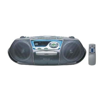
CD Portable Radio
Cassette Recorder
MCD-Z128 Series
CWM-240
MCD-Z130 Series
(RADIO SECTION)
Tuning range ......................... FM : 87.5 - 108 MHz
(GENERAL SECTION)
Power output ......................... 2W/ch (DC max)
Speaker ................................. 10 cm x 2
Terminal impedance ............. PHONES : 32 ohms
Power source ........................ AC : 120V, 60Hz (MX,CA)
Dimensions ........................... 472 (W) x 158 (H) x 252 (D) mm
Weight (approx.) .................... 3.0 kg (Not including batteries)
Specifications subject to change without notice.
FILE NO.
CWM-240
(MX)
MCD-Z128 series
MCD-Z130 series
PRODUCT CODE No.
164 073 07 CWM-240/MX
164 073 02 MCD-Z128F/XE
164 073 06 MCD-Z128F/AU
164 073 00 MCD-Z130F/XE
164 073 01 MCD-Z130/CA
164 073 03 MCD-Z130F/AU
164 073 04 MCD-Z130F/PA
164 073 30 MCD-Z130L/UK
AM : 526.5 - 1,606.5 kHz
LM : 148.5 - 283.4 kHz(130L Only)
: 230V, 50Hz (XE,UK)
: 230-240V, 50Hz (AU)
: 110-120/220-240V, 50/60Hz (PA)
DC : 12 V (8 "R20/D" batteries)
SM
5810232
REFERENCE No.
Table of Contents

Related Manuals for Sanyo CWM-240


Summary of Contents for Sanyo CWM-240
-
Page 1: Specifications
MCD-Z128 series MCD-Z130 series MCD-Z128 Series CWM-240 MCD-Z130 Series PRODUCT CODE No. 164 073 07 CWM-240/MX 164 073 02 MCD-Z128F/XE 164 073 06 MCD-Z128F/AU 164 073 00 MCD-Z130F/XE 164 073 01 MCD-Z130/CA 164 073 03 MCD-Z130F/AU 164 073 04 MCD-Z130F/PA... -
Page 2: Laser Beam Safety Precaution
LASER BEAM SAFETY PRECAUTION • Pickup that emits a laser beam is used on this CD section. CAUTION : USE OF CONTROLS OR ADJUSTMENTS OR PERFORMANCE OF PROCEDURES OTHER THAN THOSE SPECIFIED HEREIN MAY RESULT IN HAZARDOUS RADIATION EXPOSURE. LASER OUTPUT ....0.6 mW Max. (CW) WAVE LENGTH .... -
Page 3: Tuner Adjustments (All Except Z130L)
TUNER ADJUSTMENTS (All except Z130L) Use a plastic screw driver for adjustments. Adjust the intermediate frequency of AM and FM to the frequency of ceramic filter. Set of unit Supply voltage : DC 12.0V Speaker impedance : 8 ohms Standard output : 50 mW AM COIL Function switch... -
Page 4: Tuner Adjustments (Z130L)
TUNER ADJUSTMENTS (Z130L) Use a plastic screw driver for adjustments. Adjust the intermediate frequency of AM and FM to the frequency of ceramic filter. Set of unit Supply voltage : DC 12.0V Speaker impedance : 8 ohms LW COIL MW COIL Standard output : 50 mW Function switch... -
Page 5: Tape Deck Adjustments
TAPE DECK ADJUSTMENTS 1. HEAD REPLACEMENT • After replacement, demagnetize the heads by using a degausser. • Be sure to clean the heads before attempting to make any adjustments. • All wiring should be returned to the original position after work is completed. 2. -
Page 6: Wiring Connection
WIRING CONNECTION AC IN BATTERY (15P) DC12V BROWN ORANGE BLACK CD MECHANISM (6P) YELLOW YELLOW SWITCH FM ROD ANT. CN101 DC+(0) DC+(1) (4P) AC/IN 1 AC/IN 3 RECTIFIER P.W.B CN906 (3P) CN901 CN904 CN102 TUNER (15P) (2P) (4P) P.W.B CN903 FM ANT. -
Page 7: Exploded View(Cabinet & Chassis)
EXPLODED VIEW(CABINET & CHASSIS) - 6 -... -
Page 8: Parts List
PARTS LIST PRODUCT SAFETY NOTICE EACH PRECAUTION IN THIS MANUAL SHOULD BE FOLLOWED DURING SERVICING. COMPONENTS IDENTIFIED WITH THE IEC SYMBOL IN THE PARTS LIST AND THE SCHEMATIC DIAGRAM DESIGNATE COMPONENTS IN WHICH SAFETY CAN ! ! ! OF SPECIAL SIGNIFICANCE. WHEN REPLACING A COMPONENT IDENTIFIED , USE ONLY THE REPLACEMENT PARTS DESIGNATED, OR PARTS WITH THE SAME RATINGS OF RESISTANCE, WATTAGE OR VOLTAGE THAT ARE DESIGNATED IN THE PARTS LIST IN THIS MANUAL. - Page 9 PARTS LIST REF.NO. PART NO. DESCRIPTION REF.NO. PART NO. DESCRIPTION 645 035 0092 GLASS TUBE FUSE 2 A,FS1101 C0908 403 060 8908 POLYESTER 0.033U M 50V ! ! ! (All except MX,CA) C0909 403 057 3800 POLYESTER 0.1U M 50V 645 051 6504 FUSE GLASS TUBE,FS1101(MX,CA) C0911 403 062 1105 POLYESTER 0.047U M 50V...
- Page 10 PARTS LIST REF.NO. PART NO. DESCRIPTION DISPLAY P.W.BOARD ASSY D0104 645 023 6105 ZENER DIODE REF.NO. PART NO. DESCRIPTION D0105 645 023 6099 DIODE 1N-4148 614 320 1755 ASSY,PWB,DISPLAY(Only initial) IC101 645 041 9973 IC LA1824 (240,130 series) L0104 645 023 6297 VHF COIL 614 321 0795 ASSY,PWB,DISPLAY(Only initial) L0105 645 032 9944 FTZ COIL,BH-816557...
-
Page 11: Ic Block Diagram & Description
EXPLODED VIEW & PARTS LIST (TAPE DECK MECHANISM) TAPE DECK MECHANISM CHASSIS REF.NO. PART NO. DESCRIPTION 645 050 1814 CASS DECK MECHANISM TM01 645 018 0637 R/P HEAD TM02 645 050 0985 PINCH ROLLER ARM TM01 TM04 TM03 645 030 6839 E HEAD TM04 645 050 1395 RF BELT TM02... - Page 12 IC BLOCK DIAGRAM & DESCRIPTION IC901 LA9250M (Analog Signal Processor) Pin Name Function PIN NAME Function SLOF Sled servo off control input pin. Pick-up photo-diode connection pin. Added to FTN! Pin to generate the FTN2 RF signal, subtracted from FTN1 pin to generate the FE signal. Pin for setting the function on/off, which function is tracking gain TGRF following to RF level.
- Page 13 IC BLOCK DIAGRAM & DESCRIPTION IC902 LC78602YE (Analog Signal Processor) Pin Name Function PIN NAME Function *SEG6 The segment output (6) terminal. (The pull-up resister internal ) It is junction in unused time, 0 V defect detecting signal (DEF) input DEF1 terminal *SEG5...
-
Page 14: Ic & Transistor Voltages
IC & TRANSISTOR VOLTAGES IC901 LA9250M (CD PLAY MODE) Pin No. Voltage 2.57 2.57 2.55 2.57 2.57 2.57 2.55 Pin No. Voltage 2.77 2.57 2.57 2.47 2.47 2.56 2.37 Pin No. Voltage 0.45 0.45 5.15 2.56 2.41 2.57 Pin No. Voltage 2.01 2.57... -
Page 15: Schematic Diagram (Audio For Z130 Series)
SCHEMATIC DIAGRAM (AUDIO for Z130 series) PRODUCT SAFETY NOTICE Each precaution in this manual should be followed during servicing. Components identified with the IEC symbol in the parts list and the schematic diagram designated ! ! ! components in which safety can be of special significance. When replacing a component identified by ! ! ! , use only the replacement parts designated, or parts with the same ratings of resistance, wattage or voltage that are designated in the parts list in this manual. -
Page 16: Schematic Diagram (Audio For Z128 Series)
SCHEMATIC DIAGRAM (AUDIO for Z128 series) PRODUCT SAFETY NOTICE Each precaution in this manual should be followed during servicing. Components identified with the IEC symbol in the parts list and the schematic diagram designated ! ! ! components in which safety can be of special significance. When replacing a component identified by ! ! ! , use only the replacement parts designated, or parts with the same ratings of resistance, wattage or voltage that are designated in the parts list in this manual. -
Page 17: Schematic Diagram (Audio For Cwm-240)
SCHEMATIC DIAGRAM (AUDIO for CWM-240) PRODUCT SAFETY NOTICE Each precaution in this manual should be followed during servicing. Components identified with the IEC symbol in the parts list and the schematic diagram designated ! ! ! components in which safety can be of special significance. When replacing a component identified by... -
Page 18: Schematic Diagram (Cd For Z130 Series)
SCHEMATIC DIAGRAM (CD for Z130 series) - 17 -... -
Page 19: Schematic Diagram (Cd For Z128 Series)
SCHEMATIC DIAGRAM (CD for Z128 series) - 18 -... -
Page 20: Schematic Diagram (Tuner For Xe, Pa)
SCHEMATIC DIAGRAM (TUNER for XE, PA) - 19 -... -
Page 21: Schematic Diagram (Tuner For Uk)
SCHEMATIC DIAGRAM (TUNER for UK) - 20 -... -
Page 22: Schematic Diagram (Tuner For Ca, Mx)
SCHEMATIC DIAGRAM (TUNER for CA, MX) - 21 -... -
Page 23: Schematic Diagram (Tuner For Au)
SCHEMATIC DIAGRAM (TUNER for AU) - 22 -... -
Page 24: Wiring Diagram (Cd Main)
WIRING DIAGRAM (CD MAIN) - 23 -... -
Page 25: Wiring Diagram (Tuner For Except Uk)
WIRING DIAGRAM (TUNER for except UK) - 24 -... -
Page 26: Wiring Diagram (Tuner For Uk)
WIRING DIAGRAM (TUNER FOR UK) - 25 -... -
Page 27: Wiring Diagram (Display)
WIRING DIAGRAM (DISPLAY) - 26 -... -
Page 28: Wiring Diagram (Rectifier , Rec Sw)
WIRING DIAGRAM (RECTIFIER , REC SW) RECTIFIER REC SW SANYO Electric Co., Ltd. Osaka, Japan Aug./ '01 / 2850 BB Printed in Japan...