
Related Manuals for GE RPV311

Summary of Contents for GE RPV311
- Page 1 Grid Solutions RPV311 Distributed Multifunction Fault Recorder Technical Manual Platform Hardware Version: C Platform Software Version: 13 Publication Reference: RPV311-TM-EN-7 imagination at work...
-
Page 3: Table Of Contents
CONTENTS Chapter 1: Introduction Foreword Target Audience Nomenclature Acronyms and Abbreviations Product Scope Unpacking External Indication RPV311 Nameplate RA331, RA332, and RA333 Nameplate Key Features Compliance Functional Overview Programs Under the GPL 2 License Ordering Options RPV311 RA331 RA332 RA333... - Page 4 RA332 RA333 Chapter 4: Configuration Accessing the Equipment Configuration Configuration History Equipment Identification Synchronization Communications Acquisition with remote acquisition modules Acquisition with Sampled Values Access Control User Record Management Auto Upload Voltage Circuit Current Circuits Power Circuit Digital Channels DC Channels Thresholds Adding New Voltage Thresholds Adding New Current Thresholds...
- Page 5 17.2 Data 17.3 Communication MODBUS DNP3 19.1 Configuring the DNP3 function 19.2 DNP3 configuration example Chapter 5: Operation Local Interface Status Indicators Menu Navigation Local Interface Menus Monitoring Web Interface Accessing the Monitoring Web Interface Navigating Status Manual Trigger Records Monitoring Configuration History General Information...
- Page 6 Record Format and Naming, and Mass Storage Capacity Record Format Record Naming Mass Storage Capacity Record Management and Access Chapter 7: TW Fault Locator TWFL Overview TW Fault Location Information Maximum Number of Lines Monitored by the TW Fault Locator Accuracy and TWFL with CVTs Underground and Overhead Cables Automatic Fault Location...
- Page 7 RA331, RA332 and RA333 Mechanical Installation Cables and Connectors Power Supply Connections RPV311 AC and DC Power Connection RA331, RA332 and RA333 AC and DC Power Connection Powering Up Earth Connection Connection Between RPV311 and RA331, RA332 or RA333 Analog Voltage Inputs (50/60 Hz)
- Page 8 Ready in processing module does not light up Alarm in processing module lights up SYNC does not lights up Date or time incorrect Time drift throughout operation week RPV311 Firmware Update Product Support Tools - PST RA331, RA332, and RA333 Troubleshooting indicator does not light up AINS...
- Page 9 Power Supply Environmental Conditions 1.10 Type Tests RPV311 1.11 Safety Tests 1.12 Environmental tests 1.13 Enclosure Protection IEC 60529 1.14 Dimensions RA331, RA332, and RA333 Specifications Analog Acquisition (50/60 Hz) Analog Acquisition (High-speed – Only RA333 Module) Voltage Inputs Current Inputs...
- Page 10 Table of Figures Figure 1: Functional design overview Figure 2: RA332, RA333 and RPV311 Figure 3: Front View of the RPV311 Figure 4: Back view of the RPV311 Figure 5: Rear and front views of the RA331, respectively Figure 6: Rear view of the RA332...
- Page 11 Figure 42: MODBUS configuration section Figure 43: Digital Channels Configured Figure 44: Analog channels selected Figure 45: Local interface of the RPV311 Figure 46: Status monitoring sequence Figure 47: Monitoring sequence Figure 48: Records monitoring sequence: Fault disturbance, TW and average series 103...
- Page 12 Figure 68: General Information screen Figure 69: Setup screen Figure 70: Concatenation event example Figure 71: Example of an event without concatenation Figure 72 – TW Fault Locator architecture overview Figure 73 - Typical Circuit Three-Terminal Application Figure 74 – Three terminal line application Figure 75 –...
- Page 13 Figure 109: RA33X Grounding Figure 110: RPV311 Fiber Optic Connectors Figure 111: RA331, RA332 and RA333 fiber optic connectors Figure 112: Connection between RPV311 and the RA331, RA332 or RA333 Figure 113: Screws of the Back Panel Figure 114: Analog input terminals...
- Page 14 Figure 134: Connections diagram of optical synchronism inputs Figure 135: Dry contact relays of the RPV311 Figure 136: Dry contact relay connection diagram Figure 137: Fiber-optic pair Figure 138: RPV311 Dimensions Figure 139: RA331, RA332 and RA333 dimensions Figure 140: RA331, RA332 and RA333 panel cutout...
-
Page 15: Chapter 1: Introduction
Foreword This technical manual provides a functional and technical description of Alstom Grid's Reason RPV311, as well as a comprehensive set of instructions for using the device. The level at which this manual is written assumes that you are already familiar with protection engineering and have experience in this discipline. -
Page 16: Acronyms And Abbreviations
Chapter 1 – Introduction RPV311 We would like to highlight the following changes of nomenclature however: British English is used throughout this manual The British term 'Earth' is used in favour of the American term 'Ground' Acronyms and Abbreviations AC - Alternating Current;... -
Page 17: Product Scope
XML - Extensible Markup Language. Product Scope The processing unit RPV311 and the acquisition modules RA331, RA332, and RA333 offer a distributed solution for Multifunction Digital Recording. The solution is designed for the acquisition, monitoring and recording of electrical quantities normally associated with electrical power generation, transmission or distribution equipment. -
Page 18: External Indication
External Indication RPV311 Nameplate Information about the company, power supply and the serial number and part number is shown on a small nameplate affixed to the rear of the equipment, as... -
Page 19: Key Features
Chapter 1 – Introduction RPV311 Figure 2: Location of Serial Number, Part Number and specifications Key Features The RPV311 plus RA33x acquisition modules solution presents the following key features: Acquisition system: 16-bit opto-isolated analog-to-digital converters, independent for each ... -
Page 20: Compliance
Chapter 1 – Introduction RPV311 Up to 8 fiber-optic links to connect to RA331, RA332 or RA333 remote acquisition modules; Fan-less and no rotating part design Trigger waveform recorder at 256, 128, or 64 points-per-cycle; Continuous waveform recorder at 16 points-per-cycle;... -
Page 21: Programs Under The Gpl 2 License
Chapter 1 – Introduction RPV311 The processing unit RPV311 and the acquisition modules RA331, RA332, and RA333 offer a distributed solution for Multifunction Digital Recording. The solution is designed for the acquisition, monitoring and recording of electrical quantities normally associated with electrical power generation, transmission or distribution equipment. -
Page 22: Ordering Options
Chapter 1 – Introduction RPV311 Ordering Options RPV311 Variants Order Number 7 8 9-11 12 Model Type RPV311 Multifunction Recorder RPV311 Power Supply 24-48 Vdc 100-250 Vdc / 110-240 Vac Network Interface Two RJ45 copper 100BASE-TX Ethernet interfaces Two RJ45 copper or duplex ST-type connector 100BASE-X Ethernet interfaces... -
Page 23: Ra331
RPV311 RA331 Variants Order Number 6 7 8 9 10 11 12 Model Type RA331 Acquisition Module for RPV311 RA331 Power Supply 24-48 Vdc 100-250 Vdc / 110-240 Vac Analogue Inputs 1 to 4 Voltage inputs 115 V / Current inputs 1 A; full-scale 20 A (Ith = 32 A) Voltage inputs 115 V / Current inputs 5 A;... -
Page 24: Ra332
Variants Order Number 6 7 8 9 Model Type RA33 RA332 Acquisition Module for RPV311 Power Supply 24-48 Vdc 100-250 Vdc / 110-240 Vac Analogue Inputs 1 to 4 Voltage inputs 115 V / Current inputs 1 A; full-scale 20 A (Ith = 32 A) Voltage inputs 115 V / Current inputs 5 A;... -
Page 25: Digital Inputs 17 To 32
Chapter 1 – Introduction RPV311 125 V 250 V Not installed Digital Inputs 17 to 32 24 V / 48 V 125 V 250 V Not installed Customization / Regionalisation GE branding Hardware Design Suffix Third version Issue D RPV311-TM-EN-7... -
Page 26: Ra333
RPV311 RA333 Variants Order Number 6 7 8 9 10 11 12 13 Model Type RA333 Travelling Wave and DFR Acquisition Module for RPV311 RA333 Power Supply 24-48 Vdc 100-250 Vdc / 110-240 Vac Analogue Inputs 1 to 4 Voltage inputs 115 V / Current inputs 1 A; full-scale 20 A (Ith = 32 A) Voltage inputs 115 V / Current inputs 5 A;... -
Page 27: Chapter 2: Safety Information
RPV311 Distributed Multifunction Fault Recorder Chapter 2: Safety Information This chapter provides information about the safe handling of the equipment. The equipment must be properly installed and handled in order to maintain it in a safe condition and to keep personnel safe at all times. You must be familiar with information contained in this chapter before unpacking, installing, commissioning, or servicing the equipment. -
Page 28: Installation, Commissioning And Servicing
Chapter 2 – Safety Information RPV311 Caution: Refer to equipment documentation. Failure to do so could result in damage to the equipment Risk of electric shock Ground terminal. Note: This symbol may also be used for a protective conductor (ground) terminal if that terminal is part of a terminal block or sub-assembly. - Page 29 Chapter 2 – Safety Information RPV311 Consult the equipment documentation before installing, commissioning, or servicing the equipment. Always use the equipment as specified. Failure to do so will jeopardise the protection provided by the equipment. Removal of equipment panels or covers may expose hazardous live parts.
-
Page 30: Fusing Requirements
Chapter 2 – Safety Information RPV311 The functioning of the device has been certified under the circumstances described by the standards mentioned in Chapter 17: Technical Specifications (item Type Tests). Usage of the equipment in different conditions from the specified in this manual might affect negatively its normal integrity. -
Page 31: Equipment Connections
In order to maintain the equipment’s requirements for protection against electric shock, other devices connected to the RPV311 and RA33x shall have protective class equal or superior to Class I. Watchdog (self-monitoring) contacts are provided to indicate the health of the device on some products. -
Page 32: Pre-Energisation Checklist
Chapter 2 – Safety Information RPV311 All connections to the equipment must have a defined potential. Connections that are pre-wired, but not used, should be earthed, or connected to a common grouped potential. Pay extra attention to diagrams before wiring the equipment. -
Page 33: Upgrading/Servicing
There might be situations in which the RPV311 and RA33x are operating within its environmental operational range, but the computers, equipment connected to them... -
Page 34: Standards Compliance
Chapter 2 – Safety Information RPV311 Before decommissioning, completely isolate the equipment power supplies (both poles of any dc supply). The auxiliary supply input may have capacitors in parallel, which may still be charged. To avoid electric shock, discharge the capacitors using the external terminals before decommissioning. -
Page 35: Chapter 3: Hardware Design
This chapter provides information about the hardware design of the products. Hardware Architecture The RPV311 is a multifunction processing unit and has an acquisition system with 16- bit A/D D converters that provide an acquisition rate of 256 points-per-cycle synchronized by the IRIG-B signal. -
Page 36: Processing Capability
RPV311. In order to respect the RPV311 processing capability the number of RA33x that can be connected to the RPV311 obey the following rule: The RPV311 can process 12 logical slots and each RA demands the following number of slots. Device... -
Page 37: Figure 3: Front View Of The Rpv311
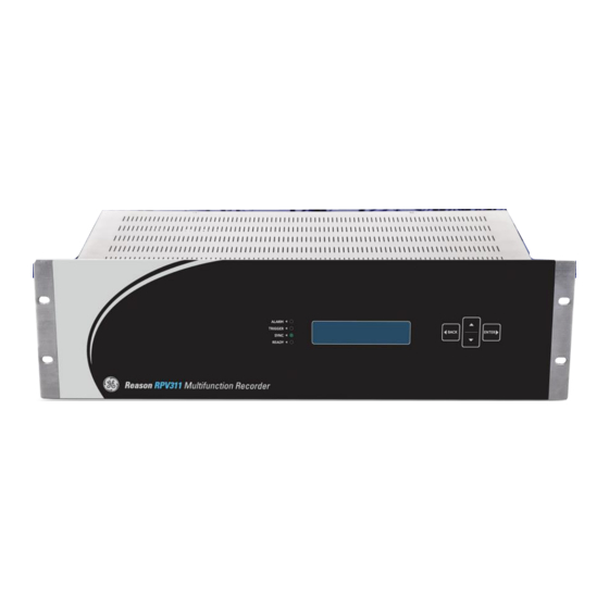
(optional). 2.1.2 Components Front view of the RPV311, showing all the main components on the front panel. Figure 3: Front View of the RPV311 Indicators of the state of the equipment:... -
Page 38: Ra331
Local interface for human-machine interaction. Buttons for navigation on the local interface. Back view of the RPV311, showing all the main components on the back panel. Figure 4: Back view of the RPV311 Up to 8 pairs of connectors for fiber-optic links. For each link there is an Act indicator that lights up when the link is receiving data of the acquisition module. -
Page 39: Figure 5: Rear And Front Views Of The Ra331, Respectively
Chapter 3 – Hardware Design RPV311 2.2.1 Main Features Up to 8 analog inputs (voltage, current, DC transducers, probes); Up to 32 digital inputs; 16-bit analog-to-digital converters, 256 points-per-cycle sampling rate; Frequency response of DC to 3.0 kHz;... -
Page 40: Ra332
Chapter 3 – Hardware Design RPV311 Front Panel Indicators: Mains lights up when the module is powered-up. Ready indicator lights up after the module self-test is completed. The Link1 indicator lights up when active. RA332 2.3.1 Key Features Up to 16 analog inputs (voltage, current, DC transducers, probes);... -
Page 41: Ra333
Chapter 3 – Hardware Design RPV311 Up to 32 digital inputs identified as 201 to 232. One connector for fiber optic links. The connector has an Act indicator that lights up when its link is active (i.e., it is receiving requests of the processing module). -
Page 42: Figure 7: Front And Back Views Of The Ra333
Chapter 3 – Hardware Design RPV311 Figure 7: Front and back views of the RA333 AC or DC power input. Rear TW and DFR indicators, that means: The Ready indicator lights up after the module's self-test is completed; The Mains indicator lights up when the module is powered;... - Page 43 The TW PPS blinks once per second indicating that the unit is synchronized. The TW LINK indicates that the TW module in the RA333 is communicating with the RPV311 processing unit. The TW READY indicates that the TW module in the RA333 is healthy.
-
Page 45: Chapter 4: Configuration
RPV311 Distributed Multifunction Fault Recorder Chapter 4: Configuration This chapter includes concise instructions of how to configure all available features in the device. Accessing the Equipment Configuration Access to the equipment's configuration is provided by the Web Interface. When the equipment is accessed, a copy of the current configuration is maintained on the equipment until a new configuration is sent. -
Page 46: Figure 8: Initial Configuration Screen
Chapter 4 – Configuration RPV311 Figure 8: Initial configuration screen Equipment identification Menu configuration items. It is recommended that the configuration of the equipment be performed item by item in top-to-bottom order. The menu items in the configuration can be configured one by one and by clicking on the... -
Page 47: Configuration History
Chapter 4 – Configuration RPV311 Configuration History The history of changes in the equipment configuration can be shown in the Web Interface. The information shown is: Revision Indicates the number of each configuration; Time stamp Indicates the date and time the configuration was changed;... -
Page 48: Synchronization
2.2.1 Time Source On the screen T it is possible to configure how the RPV311 will interpret the IME SOURCE time zone of the IRIGB signal and also the IP address of the NTPv2, 3 or 4 server. The configurable settings are:... -
Page 49: Communications
Chapter 4 – Configuration RPV311 RPV311 to identify the UTC time using information from the signal or from the manual configuration of the user: When Auto (IRIGB with extensions) is selected the RPV311 shall use the information of time zone sent within the IRIGB signal to recover the UTC time. -
Page 50: Figure 10: Equipment Ethernet Configuration Section
The Ethernet port enables the RPV to connect to the TCP / IP / UDP / IP networks. The RPV311 allows point-to-point communication with a conventional modem, cellular phone, GPRS and radio links. The Serial Port can be configured by accessing... -
Page 51: Figure 11: Equipment Serial Port Configuration Section
SE THIS PORT FOR ROUTING router for another network. D The M check box allows permanent communication between an RPV311 ODEM and a server through a telephone line. E The D... -
Page 52: Acquisition With Remote Acquisition Modules
Chapter 4 – Configuration RPV311 Acquisition with remote acquisition modules The RPV311 data acquisition can be performed by the RA331, RA332 and RA333 remote acquisition modules. The RA333 module consists of two different acquisition systems. One, called DFR, is used for analog data acquisition of 50/60 Hz of voltage, current, or DC. The other, called TW, is used for high-speed acquisition of traveling waves. - Page 53 Figure 13, it is possible to configure the analog inputs of the acquisition module connected with the RPV311 configured in the previous section. It is important to configure the analog inputs for voltage or current, according to the physical configuration of the module, shown in Chapter 15: Installation.
-
Page 54: Acquisition With Sampled Values
DJUSTMENT accuracy of the measurement. Acquisition with Sampled Values The RPV311 data acquisition can be performed by Sampled Values data, incoming of Merging Units. The acquisition is done by connecting the Process Bus Ethernet port to the Sampled Values generator. -
Page 55: Figure 14: Sampled Values Subscriptions Links Configuration Section
Chapter 4 – Configuration RPV311 To configure the links, access the S section, shown in AMPLED VALUES SUBSCRIPTIONS Figure Figure 14: Sampled Values subscriptions links configuration section A The E check box allows user to enable the Subscription link feature. -
Page 56: Access Control
Chapter 4 – Configuration RPV311 Figure 15: Analog inputs configuration section for Sampled Values channels A The P indicates the position of each analog input according to the Sampled OSITION Value message. B The I scroll box allows user to select the type of the signal to be received as NPUT Sampled Values. -
Page 57: User
Chapter 4 – Configuration RPV311 Figure 16: Equipment access control configuration section A The U check box enables use of password to SE PASSWORD FOR ALL ACCESS LEVELS access equipment operation and configuration via Web Interface. B The F text field allows user to enter an independent IRMWARE UPDATE PASSWORD password to update the firmware for the equipment. -
Page 58: Figure 17: Adding New User Section
Chapter 4 – Configuration RPV311 Figure 17: Adding new user section A The U text field allows entering a user identification (maximum 8 characters). No editing is allowed. B The N text field allows user to enter a new password to access the ASSWORD Web Interface (maximum 8 characters). -
Page 59: Record Management
Chapter 4 – Configuration RPV311 Figure 18: Changing the administrator password section: Changing the administrator password section A The O text field allows user to enter an old password. ASSWORD B The N text field allows user to enter a new password to access the ASSWORD Web Interface (maximum 8 characters). -
Page 60: Auto Upload
Chapter 4 – Configuration RPV311 Figure 19: Record management configuration section A Selecting the A check box, erases older record automatically if memory UTO ERASE capacity exceeds 90%. B The E scroll box allows user to choose a type of record (fault, disturbance, RASE ALL steady-state and SOE) to be removed. -
Page 61: Figure 20: Auto Upload Configuration Section
2.9.2 E-mail/Fax The RPV311 is capable of sending email up to 4 different addresses and fax up to 2 different numbers. Upon creating a new COMTRADE file the RPV send a warning email/fax with the name of the register that has been created. -
Page 62: Voltage Circuit
Chapter 4 – Configuration RPV311 Figure 21: Email/Fax configuration Voltage Circuit Considering the input type configurations, it is possible to create voltage circuits with 1, 2, 3, or 4 elements. The circuit sequences supported by the equipment are ABC, BCA, CAB, CBA, BAC, and CBA and may be customized by the user in the equipment setup. -
Page 63: Current Circuits
Chapter 4 – Configuration RPV311 The I scroll box allows user to select the inputs to which each measuring NPUTS element is connected. No editing allowed; The N text field allows user to enter a circuit rated voltage; OMINAL VALUE The R text fields allows user to enter ratio of power transformers for each input. -
Page 64: Figure 23: Adding And Editing Current Circuits
Chapter 4 – Configuration RPV311 The I text field allows user to enter a single code for the circuit being defined DENTIFIER (maximum 15 characters). No editing allowed; The W scroll box allows selecting a number of elements used for measuring (1, 2, IRING 3 or 4). -
Page 65: Power Circuit
Chapter 4 – Configuration RPV311 Power Circuit Power circuits can be created of circuit voltage and current. To add a new power circuit select the P section and fill in the following: OWER IRCUITS The I text field allows user to enter a single code for the circuit being defined DENTIFIER (maximum 15 characters). -
Page 66: Digital Channels
The P scroll box allows user to select the input logic level (normal or inverted); OLARITY : the RPV311 will only start a record once the binary activation time EBOUNCING TIME has exceeded the debouncing time parameter. Once the digital channel is created, it shows in the configuration interface menu. -
Page 67: Dc Channels
Chapter 4 – Configuration RPV311 Thebutton allows user to rename the digital channel. ENAME The button allows user to delete the digital channel. EMOVE DC Channels The signal of the transducer (±10 V or 0-20 mA) is converted in to the desired physical measurement using a first order transfer function with the parameters of gain () -
Page 68: Thresholds
Chapter 4 – Configuration RPV311 Figure 26: Adding and editing DC channels Thebutton allows user to rename the DC channel. ENAME The button allows user to delete the DC channel. EMOVE Thresholds Measured values are continuously monitored and may be tested once every cycle of... - Page 69 Chapter 4 – Configuration RPV311 The results of all thresholds are processed using user-definable Boolean equations and can be used to trigger the recording of fault, traveling waves, and disturbance data. The thresholds can be associated with power, voltage and current circuits, digital...
-
Page 70: Adding New Voltage Thresholds
Chapter 4 – Configuration RPV311 Adding New Voltage Thresholds To add a voltage threshold fill in the following: The S scroll box allows user to define a code of a voltage circuit used. No editing OURCE allowed; The Q scroll box allows user to select the associated magnitude to be UANTITY monitored. -
Page 71: Adding New Current Thresholds
Chapter 4 – Configuration RPV311 Figure 27: Adding and editing a voltage threshold A The button allows user to apply the hold time or the hysteresis for all PPLY ALL thresholds. B Thebutton allows user to delete the threshold. -
Page 72: Figure 28: Adding And Editing A Current Threshold
Chapter 4 – Configuration RPV311 dABC1 and dN1 - phasor variation; - positive sequence variation; − - negative sequence variation; dIIMB - unbalance variation; dIFRQ - frequency variation; dITHD - THD variation. -
Page 73: Adding New Power Thresholds
Chapter 4 – Configuration RPV311 A The button allows user to apply the hold time or the hysteresis for all PPLY ALL thresholds. B Thebutton allows user to delete the threshold. EMOVE Adding New Power Thresholds To add a power threshold, fill in the following: ... -
Page 74: Figure 29: Adding And Editing A Power Threshold
Frequency Oscillation threshold are: Oscillation magnitude (in MVA, PU and Hz), Oscillation time (in seconds) and Hysteresis (in percentage). The Operator scroll box can only be set to Greater Than. To trigger, the RPV311 uses a fixed band-pass filter adjusted at 0.1 Hz to 5 H... -
Page 75: Adding New Digital Thresholds
Chapter 4 – Configuration RPV311 Adding New Digital Thresholds To add a digital threshold, fill in the following: The S scroll box allows user to define a code of a digital channel used. No OURCE editing allowed; The C... -
Page 76: Cross-Trigger
EMOVE Cross-Trigger The cross-trigger is performed through an Ethernet broadcast UDP message sent whenever the device triggers, then all the RPV311 within the network with the cross- trigger enabled will receive the message and trigger as well. Fault Recorder The RPV311 allows user to register triggered and continuous fault recorder. -
Page 77: Figure 31: Fault Recorder - Triggered Recording Configuration Section
Chapter 4 – Configuration RPV311 Figure 31: Fault recorder – triggered recording configuration section A The E check box allows user to enable the fault recorder feature. NABLED B The P text field allows user to enter the recording time before the event in RE TIME seconds. -
Page 78: Continuous Recording
Chapter 4 – Configuration RPV311 10.2 Continuous Recording In this section, shown in the figure below, is possible to configure the equipment's continuous recorder. Figure 32: Fault recorder – continuous recording configuration section A The E check box allows user to enable the continuous fault recording NABLED feature. -
Page 79: Trigger'd Recording
Chapter 4 – Configuration RPV311 The RPV311 allows user to configure triggered and continuous disturbance recording. 11.1 Trigger'd Recording In this section, shown in Figure 33, it is possible to configure the equipment disturbance triggered recorder. Figure 33: Disturbance recorder – trigger’d recording configuration... -
Page 80: Continuous Recording
Chapter 4 – Configuration RPV311 C The T field contains all the thresholds created. The logic equation uses RIGGER LOGIC AND and OR logic operators over previously defined thresholds. Initially, all preset thresholds are displayed as implicit OR operators, one per line. -
Page 81: Traveling Waves Recorder
Traveling Waves Recorder The RPV311 allows user to configure a traveling wave recorder for fault location, by trigger. To start the configuration, it is necessary add a new recorder in accordance with the position of selected links in equipment. -
Page 82: Recommended Sources Of Trigger
Ethernet cross-trigger. Note: The maximum number of RA333 that can be connected to the RPV311 is 4. The RA333 module has to be connected to the RPV311 processing module before its initianilzaton. Otherwise a log message will tell the user to reboot the device. -
Page 83: Average Series
Chapter 4 – Configuration RPV311 RPV311 allows user to register average series, harmonics, and flicker in the steady- state recorder. 14.1 Average series Figure 36, it is possible to configure the equipment's In this section, shown in average series recorder. -
Page 84: Flicker
Chapter 4 – Configuration RPV311 Figure 37: Steady-state recorder – harmonics configuration section A The I field shows all the circuits previously configured. DENTIFIER B The T field shows the circuit type. C The check box allows the selection of preset circuits for the steady-state record formation. -
Page 85: Groups
The L , R0, X0, R1 and X1 text fields allow user to enter the transmission ENGTH line characteristics (length and impedance), for the fault location. The RPV311 uses one-end impedance fault location based on the Takagi algorithm RPV311-TM-EN-7... -
Page 86: Relays
> button allows user to delete the group. EMOVE Relays Relays indicate events or state transitions and set off the alarm on the equipment. RPV311 provides four relays: three relays set by the user and one factory default relay, which signals internal equipment failure. 16.1 On time... -
Page 87: Relays 2, 3, And 4
Chapter 4 – Configuration RPV311 Figure 40: Relays on time configuration section A The T scroll box allows user to select the relays on time for logging signaling events (1 to 10 seconds). 16.2 Relays 2, 3, and 4 In this section, shown in... -
Page 88: Figure 41: Relay Signaling Events Configuration Section
Chapter 4 – Configuration RPV311 Figure 41: Relay signaling events configuration section A The L events text field allows user to enter a code used for signaling events. Refer to for log references. The relays will stay closed during the time set Appendix A in the On time configuration (previous section). -
Page 89: Pmu
For further information about the PMU, see Chapter 8: PMU. The RPV311 is able to send up to 4 PMU in the frame of data and the configuration is divided into three sub menus: General, Data and Communication described below. -
Page 90: Modbus
Sets the respective streams of data to Commanded mode. When set to OMMANDED Commanded mode. The RPV311 can send the HDR, CFG2 and CFG3 frames according to the client’s IED request. Sets the respective streams of data to Spontaneous mode. When in PONTANEOUS Spontaneous mode it is also possible to select which CFG frame the PMU will use. -
Page 91: Dnp3
The DNP3 functionality is fully associated with the MODBUS functionality in the RPV311. To use the DNP3 protocol, it is necessary to insert a configuration key at the equipment to unlock the MODBUS and DNP3 functionalities. However, it is necessary... -
Page 92: Dnp3 Configuration Example
Chapter 4 – Configuration RPV311 To add binary data to the DNP3 slave database (RPV311), it’s just necessary to add a digital channel in the equipment’s configuration, as shown at section 6. At the RPV311 restarting proccess, the DNP3 library reads the configuration archive and adds digital channels sequentially, associating to an integer number plus an increment, starting at zero, for each digital channel. - Page 93 Chapter 4 – Configuration RPV311 Channel name RA33x input Channel type DNP3 Database associated number A201 Physical A217 Physical C201 Physical D_Linha2 B201 Physical D_Linha3 B202 Physical GOOSE GOOSE A210 Physical A211 Physical A212 Physical 19.2.2 Adding analog channels The analog data possibilites for the DNP3 communication procol are the same as for MODBUS.
-
Page 94: Figure 44: Analog Channels Selected
Chapter 4 – Configuration RPV311 Figure 44: Analog channels selected A The field is only used for analog quantities with DNP3; B Used to configure the digital inputs that will be sent. RPV311-TM-EN-7... - Page 95 Chapter 4 – Configuration RPV311 Data name MODBUS DNP3 Database Data type register number associated number Alarms: bit 0: Equipment NOK bit 1: Primary power failure bit 2: Not used bit 3: Not used bit 4: Equipment not synchronized bit 5: Fault recorder low memory...
- Page 96 Chapter 4 – Configuration RPV311 Note: The phase angles are sent in degrees for the MODBUS and radian for DNP3 RPV311-TM-EN-7...
-
Page 97: Chapter 5: Operation
This chapter provides information on possible ways to access and operate the device. . Local Interface The RPV311 has a local interface for human-machine interaction, composed of a display, navigation buttons, and status indicators, as shown in the figure below. - Page 98 Chapter 5 – Operation RPV311 1.3.1 Status The information below is displayed in the local menu: Date and time; If the equipment is in normal operation; If the equipment is using the IRIG-B timing and the signal quality;...
-
Page 99: Figure 46: Status Monitoring Sequence
Chapter 5 – Operation RPV311 Figure 46: Status monitoring sequence RPV311-TM-EN-7... - Page 100 RPV311 1.3.2 Monitoring It is possible to locally monitor the analog quantities measured by the RPV311. Quantities are separated by the name of the circuit and the data is updated once per second. To view the values related to quantities associated with a circuit, select the circuit group, choose the circuit type (voltage, current, or power) and then select the name of the circuit to be monitored.
-
Page 101: Figure 47: Monitoring Sequence
Chapter 5 – Operation RPV311 Figure 47: Monitoring sequence RPV311-TM-EN-7... - Page 102 Chapter 5 – Operation RPV311 1.3.3 Records This menu shows the list of records provided by the equipment in decreasing chronological order (of the latest to the oldest). To view a record, select the type of the record (Waveform, Synchrophasors, Steady- state, TW or SOE), and then select the date and the time of the record to be viewed.
-
Page 103: Figure 48: Records Monitoring Sequence: Fault Disturbance, Tw And Average Series
Chapter 5 – Operation RPV311 Figure 48: Records monitoring sequence: Fault disturbance, TW and average series RPV311-TM-EN-7... -
Page 104: Figure 49: Records Monitoring Sequence: Harmonics, Flicker And Soe
Chapter 5 – Operation RPV311 Figure 49: Records monitoring sequence: harmonics, flicker and SOE RPV311-TM-EN-7... - Page 105 Chapter 5 – Operation RPV311 1.3.4 Settings Shows the RPV311 configuration, related to: Equipment identification; Synchronization information; Communication settings (gateway, serial port and Ethernet); Information about voltage, current and power circuits and digital channels; Relay configuration.
-
Page 106: Figure 50: Equipment Settings Monitoring Sequence
Chapter 5 – Operation RPV311 Figure 50: Equipment settings monitoring sequence RPV311-TM-EN-7... -
Page 107: Figure 51: Circuit And Channel Settings Monitoring Sequence
Chapter 5 – Operation RPV311 Figure 51: Circuit and channel settings monitoring sequence RPV311-TM-EN-7... -
Page 108: Figure 52: Relays, Pmu And Modbus Settings Monitoring Sequence
Chapter 5 – Operation RPV311 Figure 52: Relays, PMU and MODBUS settings monitoring sequence RPV311-TM-EN-7... -
Page 109: General Information
Chapter 5 – Operation RPV311 1.3.5 General Information Shows general information about the equipment, such as: Equipment model; Processor; Module identification; Frequency; Type of sequence; Key (to enable the equipment functions); Features (features enabled). -
Page 110: Figure 53: General Information Monitoring Sequence
Chapter 5 – Operation RPV311 Figure 53: General information monitoring sequence RPV311-TM-EN-7... -
Page 111: Monitoring Web Interface
Refer to Chapter 14: Communications in order to verify the support applications and the minimum requirements needed to access all the RPV311 web interface features. To access the monitoring interface, enter the equipment's Ethernet IP in a web browser. -
Page 112: Status
Chapter 5 – Operation RPV311 C Buttons to close a section or start a new configuration. D Desktop. Web Interface navigation follows the rules below: The menu items near the arrows are expandable. To expand or compress a menu item, click on the arrow or click on the item. -
Page 113: Figure 55: Equipment Status Screen
Chapter 5 – Operation RPV311 Figure 55: Equipment status screen A Equipment status, with the following information: Date: indicates the date the equipment status was last updated in the yyyy-mm-dd hh:mm:ss + 0000 format where o is UTC time offset;... -
Page 114: Log
Chapter 5 – Operation RPV311 Figure 56: Link status screen A Indicates the date the equipment status was last updated in the yyyy-mm-dd hh:mm:ss + 0000 format where o is UTC time offset. B Link status, with the following information: ... -
Page 115: Manual Trigger
Chapter 5 – Operation RPV311 Figure 57: Log screen A The Search box allows user to choose the period of time of the oldest to the latest to display. B The Codes box allows user to search for specific logs or time intervals. For example, to search a log between 300 and 399, fill 3?? and to search a list, fill 2??, 507, 700. -
Page 116: Records
D Thebutton allows user to close the section. LOSE Records This section describes how to access different types of records on the RPV311. For details about the records, see Chapter 6: Records. The Fault recorder screen, shown in Figure 59, displays a history of equipment fault records. -
Page 117: Figure 59: Fault Recorder Screen
Chapter 5 – Operation RPV311 Figure 59: Fault recorder screen A The Search box allows user to choose the period of time of the oldest to the latest to display. B The Manual Filter box allows user to filter the records manually, according to their selection. -
Page 118: Figure 60: Fault Recorder Screen
Chapter 5 – Operation RPV311 2.6.1 Disturbance recorder The Disturbance recorder screen, shown in Figure 60, displays a history of equipment disturbance records. Figure 60: Fault recorder screen A The Search box allows user to choose the period of time of the oldest to the latest, in order to display it in the interface. -
Page 119: Figure 61: Traveling Wave Recorder Screen
Chapter 5 – Operation RPV311 F Thebutton allows user to view information about the record. This ETAILS information is also included in the .HDR file. G The button allows download of record, line per line, and saving it in the OMTRADE COMTRADE format, and compression as .zic file. -
Page 120: Figure 62: Steady-State Recorder Screen
Chapter 5 – Operation RPV311 Time stamp: indicates the date and time of event log (yyyymm-dd hh:mm:ss[.uuuuuu] ± 0000 (UTC time offset); Cause: indicates threshold exceeded; Terminal: terminal where the traveling wave was detected. E The... -
Page 121: Figure 63: Soe Recorder Screen
Chapter 5 – Operation RPV311 B The Manual Filter box allows user to filter the records manually, according to their selection. C The Average series, Harmonics, Flicker PST, and Flicker PLT boxes allow user to select only this type of record on the list. -
Page 122: Monitoring
Chapter 5 – Operation RPV311 A The Search box allows user to choose the period of time of the oldest to the latest to display. B The Manual Filter box allows user to filter the records manually, according to their selection. - Page 123 Chapter 5 – Operation RPV311 Positive sequence ¹ ² − Negative sequence ¹ ² Imbalance ¹ ² Fundamental frequency ² Total harmonic distortion ² ¹ Is not calculated for circuits of 1 element without 3-phase synthesis. ² Is not calculated for neutral circuits.
-
Page 124: Figure 64: Monitoring With Plots
Chapter 5 – Operation RPV311 2.7.2 Plots To graphically monitor the values related to circuits and DC channel quantities, access the Web Interface: Monitoring > Plots In this screen it is possible to monitor up to 6 different voltage, current, or DC channel quantities, as shown in Figure 64. -
Page 125: Figure 65: Monitoring Circuit Quantities Via Web Interface
Chapter 5 – Operation RPV311 It is possible to create a waveform or synchrophasor records using the buttons at the top right corner of the screen. 2.7.3 V & I Circuits The user will be able to monitor the values of voltage and current circuits, via Web Interface: >... - Page 126 Chapter 5 – Operation RPV311 Note: The RPV311 has an autozero automatic feature, which is a slow filter that takes about 15 minutes to filter the DC components of the reading signal and then subtracts it from the readings in order to locate the correct position of the signal reference on the graph.
-
Page 127: Configuration History
Chapter 5 – Operation RPV311 Figure 66: Monitoring the status of digital channels A Status of the digital channel. B Changes pages being monitored. C Shows the number of the page being monitored. Configuration History The Configuration History screen, shown in... -
Page 128: General Information
Chapter 5 – Operation RPV311 Figure 67: Configuration History screen A Configuration history, with the following information: Revision: indicates the number of each change in configuration; Time stamp: indicates the date and time of change in configuration; ... -
Page 129: Figure 68: General Information Screen
Chapter 5 – Operation RPV311 Figure 68: General Information screen A General information about the equipment, such as: Equipment model: model of RPV; Processor: processor type; Module identification: unique identification code of the module; Frequency: nominal frequency reference;... -
Page 130: Figure 69: Setup Screen
Chapter 5 – Operation RPV311 Figure 69: Setup screen A Information about the equipment, such as: Equipment model: model of RPV; Processor: processor type. B The Language box allows choice of the language of the Web Interface - English, Portuguese or Spanish. -
Page 131: Comtrade Files Download
RANSMIT COMTRADE files download There are four different ways to get the COMTRADE files from the RPV311 to a computer, one manual way and three automatic way. The manual method uses the web interface and is described in the item Chapter 5: Operation, 1.3.3 Records... -
Page 132: Chapter 6: Records
RPV311 Distributed Multifunction Fault Recorder Chapter 6: Records This chapter details all types of registers created by the RPV311. Continuous and Triggered Fault Records Fault records can be created in the following ways: Continuously: Measurements are continuously recorded. A new record is available each 10 minutes. -
Page 133: Sampling Rate
If the pre-fault time of the second register does not overlap the post-fault time of the first records, then the RPV311 creates two separate COMTRADE files. In the figure below, if T ≥ pre-fault time + post-fault time, then the RPV311 creates two separate COMTRADE files. -
Page 134: Trigger Burst Limiter
Chapter 6 – Records RPV311 Figure 71: Example of an event without concatenation Trigger Burst Limiter There is an user-configurable trigger burst limiter for the fault recorder. The burst limiter is based on the number of triggers time interval (both parameters are user-configurable). -
Page 135: Recorded Values
Chapter 6 – Records RPV311 Derived measurements are continuously recorded. A new record is created at each hour rollover. The record size depends on the number of derived measurements selected by the user (limited to 64). By trigger: The disturbance recorder can be triggered by a Boolean equation, by a cross-trigger signal of another recorder, by a manual trigger using the Web Interface, or by the triggering of the fault recorder. -
Page 136: Sampling Rate
Chapter 6 – Records RPV311 The Maximum Record time configures the maximum duration that the register can reach. If consecutive retriggers or a sustained fault happens, the Maximum Record time establishes the limit of time that the COMTRADE file will register. -
Page 137: Sampling Rate And Acquisition
Chapter 6 – Records RPV311 Sampling Rate and Acquisition The acquisition module RA333 has 3 independent channels (one circuit A, B, C), with an 8 bit A/D converter. The sampling frequency acquisition is 5 MHz, synchronized by a PPS signal, which means one acquisition each 200 ns. -
Page 138: Harmonics
Chapter 6 – Records RPV311 Current total harmonic Quadratic average distortion Fundamental active Simple average Power Fundamental reactive Simple average Power DC transducers Simple average The aggregation time interval is user-selectable between 1 minute or 10 minutes, synchronized to UTC minute rollover. The timestamp refers to the end of the averaging window. -
Page 139: Record Format And Naming, And Mass Storage Capacity
Alstom's Analise software. The ".tri" files have the sequence of digital events. The data was formatted according to the requirements of Alstom's Analise software. The following information about the register and the RPV311 can be found within the .zic file: ... - Page 140 Chapter 6 – Records RPV311 Parameter Format Description STARTDATE yymmdd Record’s start date (year, mounth, day) STARTTIME hhmmssuuuuuu Record’s start time (hour, minutes, seconds, microsseconds) TIMECODE soohmm Indication of timezone offset (the last three characters are included only when fractional hours...
-
Page 141: Mass Storage Capacity
500 MB The equipment can be configured to automatically remove the oldest records as the soon as mass storage occupation exceeds 90%. All RPV311 files including configuration and records are stored in the SSD non-volatile memory. Record Management and Access Records can be accessed in three ways: ... -
Page 143: Chapter 7: Tw Fault Locator
Each terminal of the line has to have a set of RPV311 processing unit+RA333 acquisition unit ; and each RPV311 has to be synchronized with a GPS Clock as accurate as possible. The signal used to extract the traveling waves if the voltage signal from the secondary circuitry of the VT. -
Page 144: Tw Fault Location Information
117 ms @ 60 Hz and 120 ms @ 50 Hz. The RPV311 takes 2 minutes to create a record and during that time the device stays in a “BUSY” status and will not record a new TW record until the BUSY status is finished. -
Page 145: Accuracy And Twfl With Cvts
Note: The maximum number of RA333 that can be connected to the RPV311 is 4. The RA333 module has to be connected to the RPV311 processing module before its initialization. Otherwise a log message will tell the user to reboot the device. -
Page 146: Three Terminal Line Application
Run the TW Fault Locator tool to find the fault location (Procedure described RPV311 manual, in topic 14.5). The fault location should be 50% of the line. Alternatively, it is possible to useone RPV311 and two RA333 connected to the same RPV311. -
Page 147: Figure 73 - Typical Circuit Three-Terminal Application
RPV311 Figure 73 - Typical Circuit Three-Terminal Application To use TWFL in the case above 3 sets of equipment are necessary: 3(RPV311 + RA333). One set for each terminal (Figure 74). In this application, it is necessary to configure two transmission lines in the TW Fault Locator tool, which means to create two powerline configuration files. -
Page 148: Examples
Chapter 9 – TW Fault Locator RPV311 Figure 74 – Three terminal line application Examples Consider the TAP point located at 50% of line A-B and 50% of line C-B. Consider the names and topology of Figure Example 1: If the result of the fault location of the line A-B returns more than 50% of the length of the line and the result of the fault location of line C-B also returns more the 50% of the length, then we know the fault is in the L1’’... -
Page 149: Figure 75 - Tw Fault Location Example 1
Chapter 9 – TW Fault Locator RPV311 Figure 75 – TW Fault Location example 1 RPV311-TM-EN-7... -
Page 150: Twfl In Mixed (Hybrid) Lines
Chapter 9 – TW Fault Locator RPV311 Figure 76 - TW Fault Location example 2 TWFL in Mixed (Hybrid) Lines A hybrid transmission line is comprised of two or more different line types. That matters for the TWFL because the velocity of the fault wave is different in each section of the line and that shall be taken into account during the fault distance calculations. -
Page 151: K Factor Calculation - Underground Section
Chapter 9 – TW Fault Locator RPV311 ≅ 1.0 ℎ √ In overhead lines, the velocity of the fault wave is very close the speed of light, between 98% and 99.5%, it means that the factor K ranges from 0.985 to 0.995. -
Page 153: Chapter 8: Pmu
RPV311 Distributed Multifunction Fault Recorder Chapter 8: PMU This chapter provides detailed information about the PMU feature. Synchrophasor Measurement and Broadcast Synchrophasors are measured and broadcast according to the specifications contained in IEEE C37.118, Standard for Synchrophasors for Power Systems. -
Page 154: Accuracy Limits
All 1A and 5A analog inputs/boards in RA33x modules have the proper accuracy necessary for the RPV311 PMU solution to be rated as level 1 compliant according to IEEE C37.118 under the condition below. -
Page 155: Communication Ports, Transmission Rates
Configuration The PMU configuration is carried out through the Web Interface. For details about the PMU configuration, see Chapter 4: Configuration. Standards Compliance The RPV311 PMU complies with the following standards: IEEE C37.118-2005 IEEE C37.118.1-2011 IEEE C37.118.2-2011 IEEE C37.118.1a-2014 WMU –... - Page 156 Chapter 8 – PMU RPV311 The WMU transmits Ethernet messages that are analogue signals calculated and sent within a PMU frame with a transmission rate equal to 4 times the system nominal frequency. The analog signal sent is a representation of a three-phase signal that is used to evaluate wide-area subcyclic oscillations.
-
Page 157: Chapter 9: Modbus
RPV311 Distributed Multifunction Fault Recorder Chapter 9: MODBUS This chapter provides detailed information about the MODBUS feature. Description Status, analog and digital data are available in MODBUS registers. Access to SCADA integration is provided over Ethernet interface. Up to 8 simultaneous connections are allowed at a maximum rate of 60 accesses per second. -
Page 158: Analog Data
Chapter 9 – MODBUS RPV311 Bit 5: Fault recording low memory Bit 6: Disturbance recording low memory Bit 7: Steady-state recording low memory Bit 8: Sequence-of-events recording low memory Bit 9: Internal failure Analog Data The user must manually associate analog data to a register number. The following analog data can be selected: ... - Page 159 Chapter 9 – MODBUS RPV311 The MODBUS configuration is carried out through the Web Interface. For details about the MODBUS configuration see Chapter 4: Configuration. RPV311-TM-EN-7...
-
Page 161: Chapter 10: Dnp3
RPV311 Distributed Multifunction Fault Recorder Chapter 10: DNP3 This chapter provides detailed information about the DNP3 feature. Description Status, analog and digital data are available in DNP3 registers. Access to SCADA integration is provided via Ethernet interface. The DNP3 functionality is fully dependent on the MODBUS functionality. -
Page 163: Chapter 11: Goose Message Detection
RPV311 Distributed Multifunction Fault Recorder Chapter 11: GOOSE Message Detection This chapter provides detailed information about the GOOSE message detection functionality. Description Digital channels can be associated with physical electrical digital inputs or associated to the detection of IEC61850, GOOSE messages. -
Page 165: Chapter 12: Software - Rpv Tools
RPV311 Distributed Multifunction Fault Recorder Chapter 12: Software – RPV Tools This chapter provides detailed information about the features, configuration and usage of the RPV Manager software. RPV Tools Description The RPV Tools are a suite of applications to be installed on the PC and allow the communication and the transfer of records between several pieces of equipment and a PC. -
Page 166: Scanner
Chapter 12 – RPV Tools RPV311 Processor 1 GHz or higher; Minimum 512 MB RAM memory; Minimum 500 MB free space on disk. Only the administrator of the system can install the RPV Tools. To check if the user is the administrator click S >... -
Page 167
Using Notepad or any other editor, open the xml configuration file located in C:\RPV\scanner\conf\conf.xml. The configuration file must be saved; otherwise, the configuration will be lost. To configure each RPV311, it is necessary to fill in the file fields as shown below: Configuration file fields
xxx ... - Page 168 Chapter 12 – RPV Tools RPV311 automatically The configuration file can be changed during the scanning process. The update will occur in the next scanning cycle, after the waiting time. Once the file is configured, scanning will be performed following the configuration of the file whenever the Scanner is started.
-
Page 169
Chapter 12 – RPV Tools RPV311
60 fault 0 yes -
Page 170: Figure 77: Directory Of The Records Received Of The Equipment
The Scanner generates a log file with all the information about the ongoing process. The log messages are available in the directory C:\RPV\scanner\log\scanner.log 1.2.8 Troubleshooting Problem Solution The connection with the RPV311 was Check if the modem or the network is working not possible RPV311-TM-EN-7... -
Page 171: Configuration Tool
Chapter 12 – RPV Tools RPV311 Configuration Tool 1.3.1 Description The Configuration Tool allows creation of offline equipment configuration and sending of it to several RPV's. With this tool it is possible to make a safety backup of all the equipment configurations and either export them to a file server or keep them locally on the user's PC. - Page 172 Chapter 12 – RPV Tools RPV311 B List of equipment configurations stored locally: Equipment configurations Name Configuration name defined by the user Location Shows location of the equipment. The location of the equipment is defined in the RPV configuration. This information is read of the E >...
- Page 173 Chapter 12 – RPV Tools RPV311 1.3.3 How to Use It To open the Configuration Tool, double click on the Conftool icon and wait while default Web browser is opening. To close the Configuration Tool, close the Web browser window.
- Page 174 Chapter 12 – RPV Tools RPV311 Double click Conftool icon. The Configuration Tool interface will open in the default Web browser; Click on the button. A new window will open; MPORT Click on the Browse button to choose the configuration file previously saved on the computer;...
-
Page 175: Tw Fault Locator
Chapter 12 – RPV Tools RPV311 1.3.10 Transmitting a Configuration To be able to transmit an equipment configuration, the user must be connected to the equipment by an Ethernet or Modem interface. Select the name of the stored configuration to be sent and click on the... -
Page 176
Chapter 12 – RPV Tools RPV311 Power line file configuration
nnn Nominal length of the line as the owner of the line claims (in kilometers)nnn Is the coefficient related to the length of the line, represents the actual length of the cable of the line. -
Page 177
RPV311 Below is an example of the power line configuration:
248.5993 248.28 0.98658 substation1,RPV311-TW,term _ a substation2,RPV311-TW,term _ b -13.82689 -48.29898 0 -
Page 178: Figure 79: Fault Locator Interface
Chapter 12 – RPV Tools RPV311 Figure 79: Fault Locator Interface A Selection of the power line to be checked. The lines available are these with XML files already configured by the user. To appear in the list, the files must be stored the directory C:\RPV\faultlocator\conf. -
Page 179: Figure 80: Graphical Tool Of Fault Locator Interface
Chapter 12 – RPV Tools RPV311 E Location of the fault of terminals A and B. In order to locate a fault, select a power line configuration and then, select one record of terminal A and the related record of terminal B is automatically selected. -
Page 180: Goose Configurator
Chapter 12 – RPV Tools RPV311+ < > position the cursor each 50 µs; HIFT LEFT RIGHT ARROW+ < > position the cursor each 100 µs; LEFT RIGHT ARROW position the cursor at the record beginning;... -
Page 181: Figure 81: Initial Screen Of The Goose Configurator
Chapter 12 – RPV Tools RPV311 1.5.2 Interface When installing the RPV Tools, it creates a desktop icon for quick access. The configuration interface can be accessed directly via this icon. To access the configuration interface, do the following: Click Start > Programs > Accessories > Command Prompt;... - Page 182 Chapter 12 – RPV Tools RPV311 Starting a Configuration To perform a configuration, it is possible to either edit a pre-existing configuration on the equipment, create a new configuration,or open a file containing a pre- existing configuration. Receiving an equipment configuration >...
-
Page 183: Figure 82: Screen To Configuration On The Scl File
Chapter 12 – RPV Tools RPV311 Figure 82: Screen to configuration on the SCL file Thebutton is to confirm the changes in the files list. The button is to ANCEL cancel the changes. The ... -
Page 184: Figure 83: Association Of A Goose Control Block With A Digital Input
Chapter 12 – RPV Tools RPV311 Figure 83: Association of a GOOSE Control Block with a digital input Filter parameters To edit the filter parameters, access T > F . A screen will open and OOLS ILTER ARAMETERS show the parameters that can be changed, shown in Figure 84. -
Page 185: Figure 84: Filter Parameters
Chapter 12 – RPV Tools RPV311 Figure 84: Filter parameters Transmission of the Configuration Transmitting the configuration To transmit the configuration to the RPV access C > T . A window OMMUNICATION RANSMIT will open for user to enter the RPV IP address, and then click on the... - Page 186 Chapter 12 – RPV Tools RPV311 View the Configuration Files To view the contents of the configuration file to be sent to the equipment, access > V . A new window will open only for reading OOLS IEW THE ONFIGURATION ILES of data, it cannot be modified.
-
Page 187: Chapter 13: Software - Rpv Manager
System Monitor Figure 85 - RPV Manager main window The software main tab is called System Monitor. All the substation and RPV311 configured in the software are listed in a tree menu on the left corner of the window. The top level of the tree shows the user created facilities and the equipment installation on the second level. -
Page 188: Figure 86 - Downloaded Records
Chapter 13 – RPV Manager RPV311 By right-clicking on the equipment, the user can update the State of the equipment, through the option "Refresh", or access the equipment web configuration page, through the option "Access Web Configuration". The records highlighted yellow are stored only in equipment memory which can be seen each time Refresh occurs. -
Page 189: Rpv Manager Settings
Chapter 13 – RPV Manager RPV311 2.1.3 Auto Polling With the Auto Polling tab the user can check the number of files that have been downloaded and the number of files waiting to be downloaded. When active, the software will check which records have not yet been saved and will download them. - Page 190 Chapter 13 – RPV Manager RPV311 Compares the local configuration file with the respective RPV311 configuration file. Close the software with the "Exit" option. Settings Menu 2.2.2 In the Settings menu, the user can: Create, edit and remove Installations;...
-
Page 191: Figure 88: Device Window
Chapter 13 – RPV Manager RPV311 Figure 88: Device window There are two parameters to be configured by the user: Enable Auto COMTRADE Download: When enabled, the unit will be part of the Auto Polling process, where records not yet saved are automatically downloaded. -
Page 192: Figure 89- Transmission Line Configuration
Chapter 13 – RPV Manager RPV311 Figure 89- Transmission Line configuration In order to add and edit a transmission line, the user must: Select the installation A at one terminal of the line; Select the device A that is monitoring the line in installation A;... -
Page 193: Figure 91: Terminal Name Configuration
Figure 92- Warning menu Send email when the RPV311 being monitored have active alarms, when a fault is found in the COMTRADE files. In case a fault has been identified it is possible to attach the COMTRADE file of that fault to the email. -
Page 194: Figure 93 - Tools Menu
Calculate Traveling Wave fault location; Execute the GOOSE configuration tool Chapter 12, Section 1.5 GOOSE Configurator; Execute the RPV311 Configuration tool and manage the software plugins View records history; Search for records (with date filter); ... - Page 195 This option opens the GOOSE configuration software described in Chapter 12, Section 1.5 GOOSE Configurator. The GOOSE configuration software is responsible for the association of the SCL file of the sending IED with the RPV311 GOOSE inputs. 1.1.1.9 CONFIGURATION TOOL This option open the Configuration Tool described in Chapter 12, section 1.3...
- Page 196 Chapter 13 – RPV Manager RPV311 Selection of one or more equipment; Period start and/or end of the occurrence of the registry; Reason of occurrence; Record type: All (This will get all types of records); ...
-
Page 197: Figure 94: Percentage Of Records Chart
Chapter 13 – RPV Manager RPV311 Figure 94: Percentage of records chart It is possible for certain periods to have no downloaded files available so no graph will be loaded on the interface. Configuration Menu 2.2.5 In the Configuration menu, the user can: ... -
Page 198: Figure 95: Polling Configuration
Chapter 13 – RPV Manager RPV311 Figure 95: Polling configuration Polling Configuration fields description: COMTRADE Directory: directory path where the new records are downloaded and where the fault locator calculation searches. Display Downloaded COMTRADES Limit: maximum COMTRADE records already downloaded that will be displayed on the screen Display Available COMTRADE Age (day): limit, in days, of downloaded records that will be fetched and displayed on the screen. -
Page 199: Automatic Tw Faul Location
COEFFICIENTS The TW fault location algorithm uses a few coefficients during the fault location process. The RPV Manager default coefficients shall not be altered unless advised by GE Grid Solutions. 1.1.1.17 EMAIL Allows the configuration of the email accout that the RPV Manager will use to send emails. - Page 200 Chapter 13 – RPV Manager RPV311 2.3.1 Description After the fault location calculations are performed, the distance to fault is displayed on the software interface and it is made available via MODBUS communication according to the MODBUS IDs configured on the Transmission Line configuration menu and the IP address configured in the windows Ethernet properties of the RPV Manager computer.
-
Page 201: Polling And Refresh
Chapter 13 – RPV Manager RPV311 the correct time stamp for the fault. As the time window to track the fault waveform in narrow down using this method, various system noises are eliminated from the calculations increasing significantly the chances to automatically find the fault. - Page 202 Chapter 13 – RPV Manager RPV311 To ensure that the software starts with the Auto Refresh option active, check the box "Auto Polling on Init" on the Configuration>Polling menu; The refresh action also happens during the: Start of application execution;...
- Page 203 Chapter 13 – RPV Manager RPV311 If the execution time of the Polling process exceeds the polling interval configured, the next polling procees will be ignored until the pending execution ends. RPV311-TM-EN-7...
-
Page 205: Chapter 14: Communications
(Modem). This interface can be used only to communicate by Modem. Electrical and Optical Ethernet The RPV311 has 2 electrical 10 / 100 Mbps Ethernet interfaces for configuration, monitoring and GOOSE reading and one electrical 100 Mbps Ethernet interface for... -
Page 206: Serial Port
Gateway default setting Gateway 192.168.0.1 Serial Port The RPV311 has a serial communication port, shown in Figure 99, for connection through modem, which can be used to transfer records. The port can be configured by the user through the Web Interface. -
Page 207: Figure 99: Serial Communication Port
DB9- Signal Female Not used In order to convert the RPV311 pinout to standard RS232 pinout, the user shall use a cable or adapter with the following pinout specification: DB9 Male DB9 Male RPV311-TM-EN-7... -
Page 208: Communication Ports And Protocols
Chapter 14 – Communications RPV311 Communication Ports and Protocols To guarantee the full permission for communication equipment via Ethernet, it is necessary that the following ports and protocols are freed: Port Protocol TCP / IP Remote record download, automatic record upload, firmware upgrade, remote diagnostics and maintenance. -
Page 209: Direct Communication Using The Electrical Ethernet Port
To achieve this, configure the network connection of the computer according to the IP address, Broadcast and Netmask of the equipment, as shown below: Given the following IP address, broadcast and netmask of the RPV311: RPV311-TM-EN-7... -
Page 210: Checking The Connection
(Sampled Values measured on monitored Power System). It is not possible to communicate to this RPV311 using that Ethernet port for s their purposes. Checking the Connection In order to verify whether the equipment connection is correctly set up, connect a crossover network cable between the computer and the equipment and, using a command line terminal, run a ping command to the IP address of the equipment. -
Page 211: Communication Through Network Using The Serial Port
Chapter 14 – Communications RPV311 For communication through a network using the electrical Ethernet port, connect, using a pin-to-pin cable, one of the Ethernet Ports of the equipment to the same network as the computer, as shown in Figure 101. -
Page 212: Accessing The Equipment
Chapter 14 – Communications RPV311 Default username and password to connect via modem Username PQFW Password PQFW Then, click on thebutton to end the configuration. To access the Web Interface of the RPV-311, verify the Server IP Address of the connection properties and then, enter this IP address in the web browser. -
Page 213: Communication Configuration
RPV311 Communication Configuration It is possible to configure the communication ports (Ethernet, Gateway and Modem) of the RPV311 in the Web Interface. For communication configuration details, refer to Chapter 4: Configuration. Auto Upload When any new record is generated, it can be transmitted to up to two different servers automatically. -
Page 214: Chapter 15: Installation
RPV311 Distributed Multifunction Fault Recorder Chapter 15: Installation This chapter provides information about the product installation. Handling the Goods Our products are of robust construction but require careful treatment before installation on site. This section discusses the requirements for receiving and unpacking the goods, as well as associated considerations regarding product care and personal safety. -
Page 215: Dismantling The Goods
Mounting the Device RPV311 Mechanical Installation The RPV311 must be installed in a 19-inch rack. The RPV311 must be installed at least 10 cm away from any other equipment to avoid obstruction of air circulation impairing the cooling efficiency. RPV311-TM-EN-7... -
Page 216: Ra331, Ra332 And Ra333 Mechanical Installation
Chapter 15 – Installation RPV311 Figure 102: Minimum distances for the equipment mounting The screws for fixing the equipment are of the M6 type. The curvature of fiber-optic connected to the back of the equipment must have a minimum radius of 30 mm. -
Page 217: Cables And Connectors
Power Supply Connections The RPV311, RA331, RA332 and RA333 can be powered-up by DC or AC power source within the limits specified in Chapter 17: Technical Specifications. The power connections shall use insulated flexible conductors anti-flame (BWF type) with 1.5 mm²... -
Page 218: Rpv311 Ac And Dc Power Connection
RPV311 AC and DC Power Connection Figure 106 show the wiring diagram for the AC and DC of the RPV311 respectively. Figure 106: AC/DC power connection For compliance with IEC 61010, install a suitable external switch or circuit breaker in each current-carrying conductor of RPV311 power supply;... -
Page 219: Ra331, Ra332 And Ra333 Ac And Dc Power Connection
Chapter 15 – Installation RPV311 The switch or circuit-breaker must be suitably located and easily reachable, also it shall not interrupt the protective earth conductor. Information about nominal voltage range, maximum voltage range, frequency and power consumption, refer to Specifications Chapter 17: Technical Specifications. -
Page 220: Earth Connection
10 mm wide with M6 ring lug. As shown in the Figure 108. Figure 108: RPV311 Grounding 9.1.1 RA33x Earthing To ensure proper operation of the equipment under adverse conditions of... -
Page 221: Connection Between Rpv311 And Ra331, Ra332 Or Ra333
The RA331, RA332, and RA333 can be connected to the same RPV311 processing module. Each link on the RPV311, composed of a pair of fiber-optic connectors, is named from A to H. For each link, an optical fibers pair is used to make transmission and reception of data between the processing module and the acquisition modules. -
Page 222: Figure 111: Ra331, Ra332 And Ra333 Fiber Optic Connectors
The corresponding fibers must be linked to the acquisition module so that the TX of RPV311 is connected to the RX of the RA331, RA332, or RA333 and RX of RPV311 is connected to the TX of the RA331, RA332, or RA333, according to Figure 112. -
Page 223: Figure 113: Screws Of The Back Panel
Chapter 15 – Installation RPV311 The length of the fiber-optic cables shall not exceed 2 km. Make sure to use the appropriate optical fiber, considering its curvature radius. For information about optical fiber types and link specifications, see Chapter 17: Technical Specifications. -
Page 224: Analog Voltage Inputs (50/60 Hz)
Chapter 15 – Installation RPV311 Closed Closed Open Re-fit the board in the case until perfectly connected. Secure the case by screwing the back panel and connecting the terminal cables. Analog Voltage Inputs (50/60 Hz) The RA331, RA332, and RA333 modules have up to 8, 16 or 8 analog inputs, respectively, which can be configured for measurement of voltage. -
Page 225: Figure 115: Screws Of The Back Panel
Chapter 15 – Installation RPV311 Figure 115: Screws of the Back Panel Remove the board corresponding to the channel to be configured. In order to configure a channel for voltage, connect the jumper between positions 1 and 2 as shown in Figure 116. - Page 226 For information about analog voltage inputs specifications, see Chapter 17: Technical Specifications. 11.1.1 Connection diagram of the voltage inputs The RPV311 provides the capability for making some different voltage signal connections for a 3-phase circuit: Connection diagram of the voltage inputs...
- Page 227 Chapter 15 – Installation RPV311 3-element (Phases A, C and neutral) connection: in this case, the fourth element is derived values measured other elements. The three elements are equivalent to the values applied to the equipment. 3-element (Phases B, C and...
-
Page 228: High-Speed Analog Voltage Inputs (Tw)
Chapter 15 – Installation RPV311 Connection diagram for 1 voltage element connection 1-element connection: Connection diagram of 1 element (phase A, B or C). 1-element connection: Connection diagram of 1 element (neutral). In all cases, the equipment will compute the phase-to-ground voltage and the neutral voltage. -
Page 229: Analog Current Inputs
For information about analog voltage inputs specifications, refer to Chapter 17: Technical Specifications. 12.1.1 Connection diagram of the TW inputs The RPV311 provides the capability for connecting one 3-phase circuit (phases A, B, and C): Connection diagram for TW inputs... -
Page 230: Figure 119: Screws Of The Back Panel
Chapter 15 – Installation RPV311 In order to configure the analog input to measure current signals, remove all connectors and cables which are connected to the module and remove the back panel of the RA331, RA332 or RA333, removing the 12 screws of the panel and the... - Page 231 For information about analog current inputs specifications, see Chapter 17: Technical Specifications. 13.1.1 Connection diagram of the current inputs The RPV311 provides the capability for connecting some different current signal connections for a 3-phase circuit: Connection diagram of the current inputs...
- Page 232 Chapter 15 – Installation RPV311 3-element (Phases A, C and neutral) connection: in this case, the fourth element is derived of the values measured by the other elements. The three elements are equivalent to the values applied to the equipment.
-
Page 233: Analog Dc Transducer Inputs ± 10 V
Chapter 15 – Installation RPV311 Connection diagram for 1 current element connection 1-element connection: Connection diagram of 1 element (phase A, B or C). 1-element connection: Connection diagram of 1 element (neutral). In all cases, the equipment will compute the line current and the neutral current. -
Page 234: Figure 122: Screws Of The Back Panel
Chapter 15 – Installation RPV311 In order to configure the analog input to measure voltage signals of DC transducers, remove all connectors and cables which are connected to the module and remove the back panel of the RA331, RA332 or RA333, removing the 12 screws of the panel and the screw of the protective grounding, as shown in Figure 122. -
Page 235: Analog Dc Transducer Inputs ± 20 Ma
Chapter 15 – Installation RPV311 Place the board back in the case. Secure the case by screwing the back panel and connecting the terminals cables. Connections shall use insulated flexible wires of 1.5 mm² cross section, 8 mm ring terminals, and M3 holes. -
Page 236: Figure 126: Screws Of The Back Panel
Chapter 15 – Installation RPV311 In order to configure the analog input to measure currents signals of DC transducers, remove all connectors and cables which are connected to the module and remove the back panel of the RA331, RA332 or RA333, removing the 12 screws of the panel and the screw of the protective grounding, as shown in Figure 126. -
Page 237: Current Clamps
Chapter 15 – Installation RPV311 Figure 127: Internal Jumper Place the board back in the case. Secure the case by screwing the back panel and connecting the terminals cables. Connections shall use insulated flexible wires of 1.5 mm² cross section, 8 mm ring terminals, and M3 holes. -
Page 238: Digital Inputs
Chapter 15 – Installation RPV311 After setting the internal jumper and reassembling the device, connect the outputs of the current clamp to the correct inputs terminals of the RA respecting the polarity of the outputs and the inputs, as shown in the figure below. -
Page 239: Time Synchronization Inputs
If the IRIG-B signal is not valid or not connected, the device indicates no sync. If the IRIG-B signal is connected and valid, the time quality of the time reference reported in the IRIG-B frame is shown by the RPV311, but the time quality is not considered by the synchronization. -
Page 240: Dry Contact Relays
Information about optical synchronism inputs specifications, see Chapter 17: Technical Specifications. Dry Contact Relays The RPV311 has 4 electromechanical signaling relays. Each relay has one dry contact, as shown in Figure 135. The first relay contact is normally closed and it opens when the unit goes into operation and it is not configurable by the user. -
Page 241: Case Dimensions
Chapter 15 – Installation RPV311 Figure 135: Dry contact relays of the RPV311 19.1.1 Dry contact relay connection diagram Figure 136: Dry contact relay connection diagram For information about relay outputs specification, see Chapter 17: Technical Specifications. Case Dimensions RPV311... -
Page 242: Rpv311 Accessories
Chapter 15 – Installation RPV311 The RPV311 dimensions are shown in Figure 138. Dimension in accordance to IEC 60297-3. RPV311 Accessories Fiber-optic pair, ST connector (Q026): Fiber type Multimode 62.5 / 125 µm Curvature ratio (min) 30 mm Connector Figure 137: Fiber-optic pair... -
Page 243: Ra33X
Chapter 15 – Installation RPV311 Figure 138: RPV311 Dimensions RA33x RA331, RA332 and RA333 dimensions Height (panel) 220.92 mm (5 U) Width (panel) 241.3 mm ( 19’’) Width (body) 100 mm Weight < 3.0 kg RPV311-TM-EN-7... -
Page 244: Figure 139: Ra331, Ra332 And Ra333 Dimensions
Chapter 15 – Installation RPV311 The RA331, RA332, and RA333 dimensions are shown in Figure 139. Figure 139: RA331, RA332 and RA333 dimensions RPV311-TM-EN-7... -
Page 245: Figure 140: Ra331, Ra332 And Ra333 Panel Cutout
Chapter 15 – Installation RPV311 23.1.1 Panel Cutout The RA331, RA332 and RA333 panel cutout is shown in Figure 140. Figure 140: RA331, RA332 and RA333 panel cutout RPV311-TM-EN-7... -
Page 246: Ra33X Accessories
Chapter 15 – Installation RPV311 RA33x Accessories RA33x accessories Mounting panel to install two remote acquisition modules (RA331 / RA332 / RA333) in a 19-inch rack + blank plate to to cover one cutout in case only one RA33x is being used. -
Page 247: Chapter 16: Maintenance And Troubleshooting
RPV311 Distributed Multifunction Fault Recorder Chapter 16: Maintenance and Troubleshooting This chapter provides information about proper equipment maintenance and troubleshooting. The troubleshooting part of the chapter allows an error condition on the IED to be identified so that appropriate corrective action can be taken. -
Page 248: Replacing The Unit
Chapter 16 – Maintenance and Troubleshooting RPV311 The RPV311 has a small coin-battery battery to power the internal clock. It is advisable that the battery is not replaced. In case of such need, contact the GE support center. 1.1.1 Alarms First check the alarm status LED to see if any alarm conditions exist. -
Page 249: Watchdog
Watchdog The RPV311 presents an internal watchdog algorithm. This algorithm verifies, every second, if the device’s system is responding correctly. Case the system does not respond the device performs a hardware reboot while the output relay 1 signals that the RPV311 is off. -
Page 250: Sync Does Not Lights Up
Verify the NTP/SNTP server and guarantee this alternative source of timing. RPV311 Firmware Update When installing the application software package accompanying the equipment (refer to Software Installation), the Firmware Upgrade Tool (FUT) is installed and associated having an files with extension .fw allowing an RPV firmware update to be... -
Page 251: Product Support Tools - Pst
Chapter 16 – Maintenance and Troubleshooting RPV311 Enter the password for firmware updating and press; NTER The entire updating process is performed automatically and can be followed on the PC screen; The process requires resetting of the equipment. Therefore, answer <... -
Page 252: Link With The Processing Module Is Not Active
Chapter 16 – Maintenance and Troubleshooting RPV311 Link with the processing module is not active Make sure that Link and Act indicators are lit; Verify that the fiber-optic cables are properly connected in the RA332 and in the processing module;... - Page 253 Chapter 16 – Maintenance and Troubleshooting RPV311 Perform a visual inspection on the device to make sure there are no remainders of the repair service inside the casing or any other noncompliance; Place back the top side of the case and fasten it using the proper screws;...
-
Page 254: Chapter 17: Technical Specifications
RPV311 Distributed Multifunction Fault Recorder Chapter 17: Technical Specifications This chapter describes the technical specifications of the product. RPV311 Specifications Electrical Ethernet Port Electrical Ethernet - Ports 1 and 2 Configuration, monitoring and GOOSE Interface 10BASE-T / 100BASE-TX Bit Rate... -
Page 255: Modem Serial Port
Chapter 17 – Technical Specifications RPV311 Interface 10BASE-T / 100BASE-TX Bit Rate 10 / 100 Mbps Connector Wavelength 1300nm Fiber Type Multimode 62.5 / 125 µm Emission Power - 20 dBm Receiver sensitivity - 32 dBm Maximum Applicable - 14 dBm... - Page 256 Chapter 17 – Technical Specifications RPV311 Minimum voltage input 4.20 V Maximum input voltage 9.80 V Impedance > 500 kΩ Connector PCB pluggable Isolation Level 1.44 KVdc RPV311-TM-EN-7...
-
Page 257: Optical Irig-Input (Optional)
Chapter 17 – Technical Specifications RPV311 Optical IRIG-Input (optional) Optical IRIG Signal IRIG-B004 Wavelength 820 nm Fiber type Multimode 62.5 / 125 µm Connector Sensitivity - 24 dBm Dry-contact Relay Outputs Dry-contact Relay Outputs Max Voltage 250 Vdc Max Current... -
Page 258: Fiber-Optic Links
Chapter 17 – Technical Specifications RPV311 Fiber-optic Links Fiber-optic Links Wavelength 1300 nm Fiber Type Multimode 62.5 / 125 µm Connector Emission Power - 20 dBm Receiver sensitivity - 32 dBm Maximum Applicable - 14 dBm Power Power Supply Power Supply... -
Page 259: Environmental Conditions
5 … 95 %, noncondensing As tested per 60068-2-1 -40°C As tested per 60068-2-2 +55°C 1.10 Type Tests RPV311 EMC tests were performed according to IEC 60255-26 referring to the following standards Type Tests RPV311 IEC 61000-4- 8kV contact / 15KV air (level 4) - Page 260 Chapter 17 – Technical Specifications RPV311 A.C. and d.c. voltage dips Test level: 0% residual voltage Duration time a.c.: 1 cycle d.c.: 16,6ms Test level: 40% residual voltage Duration time a.c.: 12 cycles IEC 61000-4- d.c.: 200ms 11:2004 IEC 61000-4-...
- Page 261 Chapter 17 – Technical Specifications RPV311 Number of repetition: 3 Test level: 15 % of rated d.c. value IEC 61000-4- 17:1999 Test frequency: 120Hz, sinusoidal waveform. Voltage oscillation frequency: 1MHz IEC 61000-4- Differential mode: 1kV peak voltage; 18:2006 Common mode 2,5kV peak voltage...
-
Page 262: Safety Tests
Chapter 17 – Technical Specifications RPV311 Cross-over Frequency: 8.14Hz Severity: 7.5mm zero-peak displacement below 8.14Hz 2g zero-peak acceleration above 8.14Hz Sweep Rate: 1 Octave/minute Number of Sweep Cycles: 1 Configuration: Operational throughout Vertical Axis: Frequency Range: 1Hz – 35Hz Cross-over Frequency: 8.42Hz Severity: 3.5mm zero-peak displacement below... -
Page 263: Environmental Tests
Chapter 17 – Technical Specifications RPV311 1.12 Environmental tests Environmental tests IEC 60068-2-1 -40°C, 16 hours (Cold) IEC 60068-2-2 +55°C, 16 hours (Dry heat) IEC 60068-2-30 95% no condensation, 55°C (Damp heat) IEC 60068-2-14 -40°C to 55ºC / 9 hours / 2 cycles (Change of... -
Page 264: Dimensions
133.55 mm (3 U) Height (rear) 86 mm Width (front panel) 482.6 mm (19’’) Width (rear) 427 mm Depth 260 mm Weight < 4.0 kg The RPV311 dimensions are shown in Figure 142. Dimension in accordance to IEC 60297-3. RPV311-TM-EN-7... -
Page 265: Figure 142: Rpv311 Dimensions
Chapter 17 – Technical Specifications RPV311 Figure 142: RPV311 Dimensions RPV311-TM-EN-7... -
Page 266: Ra331, Ra332, And Ra333 Specifications
Chapter 17 – Technical Specifications RPV311 RA331, RA332, and RA333 Specifications Analog Acquisition (50/60 Hz) Analog acquisition specifications (50/60Hz) Resolution 16 bits Acquisition Rate 256 ppc Bandwidth DC to 3.0 kHz Attenuation @ 3000 Hz < 0.1 dB Attenuation @ 6400 Hz >... -
Page 267: Current Inputs
Chapter 17 – Technical Specifications RPV311 Impedance > 200 kΩ Burden I < 0.1 VA Continuous Overload 230 V (2 x Maximum Overload (1 s) 460 V (4 x Current Inputs Current inputs specifications (50/60Hz) Nominal Current 5 A (Measurement (... -
Page 268: Dc Transducer Inputs
Chapter 17 – Technical Specifications RPV311 Impedance 1 Ω Burden < 0.01 VA Continuous Overload 0.5 A Maximum Overload (1 s) DC Transducer Inputs DC Transducer inputs specifications Full Scale ± 10 V ± 20 mA Input range - 10 to + 10 V... -
Page 269: Fiber-Optic Links
Chapter 17 – Technical Specifications RPV311 Fiber-optic Links Fiber-optic links specifications Wavelength 1300 nm Fiber Type Multimode 62.5 / 125 µm Connector Emission Power - 20 dBm Receiver sensitivity - 32 dBm Maximum Applicable Power - 14 dBm RA33x Power Supply... -
Page 270: Environmental Conditions
Chapter 17 – Technical Specifications RPV311 2.10 Environmental Conditions RA33x Environmental Conditions Operating temperature range -40 … +55 °C Maximum operating altitude 2000 m (6560 ft) Relative humidity 5 … 95 % noncondensing Tested as per 60068-2-1 -40°C Tested as per 60068-2-2 +85°C... - Page 271 Chapter 17 – Technical Specifications RPV311 Test level: 40% residual voltage Duration time a.c.: 12 cycles d.c.: 200ms Test level: 70% residual voltage Duration time a.c.: 30 cycles d.c.:500ms A.C. and d.c. voltage interruptions Test level: 0% residual voltage Duration time a.c.: 300 cycles...
- Page 272 Chapter 17 – Technical Specifications RPV311 Gradual Startup Shut-down ramp: 60s Power off: 5m Start-up ramp: 60s CISPR11:2009 Radiated emission Limits: 30 to 230MHz – 50dB(μV/m) quasi peak at 3m 230 to 1000MHz – 57dB(μV/m) quasi peak at 3m CISPR22:2008...
-
Page 273: Safety Tests
Chapter 17 – Technical Specifications RPV311 Vertical Axis: Frequency Range: 1Hz – 35Hz Cross-over Frequency: 8.42Hz Severity: 3.5mm zero-peak displacement below 8.14Hz 1g zero-peak acceleration above 8.14Hz Sweep Rate: 1 Octave/minute Number of Sweep Cycles: 1 Configuration: Operational throughout 2.12... -
Page 274: Enclosure Protection Iec 60529
Chapter 17 – Technical Specifications RPV311 IEC 60255-21-2 Class 1 (Shock) 2.14 Enclosure Protection IEC 60529 Enclosure Protection IEC 60529 Front flush mounted with IP54 panel Sides IP20 Rear IP10 2.15 Dimensions RA33x dimensions Height (front panel) 222 mm (5 U) -
Page 275: Figure 143: Ra331, Ra332 And Ra333 Dimensions
Chapter 17 – Technical Specifications RPV311 Figure 143: RA331, RA332 and RA333 dimensions RPV311-TM-EN-7... -
Page 276: Current Clamps
Chapter 17 – Technical Specifications RPV311 2.16 Current Clamps Current clam specification Manufacturer / Model AEMC / MN312 Dynamic range 0.1 A … 100 A Frequency response 40 Hz … 10 kHz 2 % ± 0.02 mA (0.1 to 1 A) Accuracy 1 % ±... -
Page 277: Chapter 18: Wiring Diagrams
This chapter contains the all the possible wiring diagrams for the analogue inputs. For further details on the inputs, refer to Chapter 15: Installation. Connection Diagrams of the Voltage Inputs The RPV311 provides the capability for making some different voltage signal connections for a 3-phase circuit: Connection diagram of the voltage inputs... - Page 278 Chapter 18 – Wiring Diagrams RPV311 3-element (Phases A, B and neutral) connection: in this case, the fourth element is synthesized of the values measured by the other elements. three elements are equivalent to the values applied to the equipment.
- Page 279 Appendix A – Equipment Log RPV311 RPV311-TM-EN-7...
-
Page 280: Connection Diagrams Of The Tw Inputs
In all cases, the equipment will compute the phase-to-ground voltage and the neutral voltage. Connection Diagrams of the TW Inputs The RPV311 provides the capability for connecting one 3-phase circuit (phases A, B, and C): Connection diagram for TW inputs... - Page 281 Appendix A – Equipment Log RPV311 Connection diagram of the current inputs 4-element connection: in this case, the values shown are equivalent to the voltages of phases A, B and C, and to the neutral voltage applied to the equipment.
- Page 282 Chapter 18 – Wiring Diagrams RPV311 3-element (Phases B, C and neutral) connection: in this case, the fourth element is derived values measured other elements. The three elements are equivalent to the values applied to the equipment. 2-element connection: in this...
-
Page 283: Equipment Log
Appendix A – Equipment Log RPV311 RPV311 Distributed Multifunction Fault Recorder Appendix A Equipment Log The equipment log contains information about: Threshold violations, fault and disturbance triggers and data recording; Data record transfer (including the IP address to which data has been transferred);... - Page 284 Appendix A – Equipment Log RPV311 Battery status [value: ] Battery voltage indication Temperature normal Temperature return to normal [value: ] values Temperature high [value: Internal temperature high Temperature status Equipment temperature [value: ] indication Equipment ready Equipment normal operation...
- Page 285 Appendix A – Equipment Log RPV311 Internal clock updated by Equipment time reference IRIG-B provided by IRIG-B signal Internal clock running The internal clock is running without external without external reference reference Configuration changed Equipment set up changed [revision:] Default configuration...
- Page 286 Values (SV) packets Sampled values loss in [sv Indicates loss of Sampled stream] Values (SV) connections Stream [sv stream] up Indicates that the RPV311 is reading Sampled Values (SV) Link down The link connection was down Link up The link connection was up...
- Page 287 Appendix A – Equipment Log RPV311 Missing conditioning An conditioning module was module [slot: ] missing Invalid acquisition module Exist an invalid acquisition [slot: ] module Invalid conditioning module Exist an invalid conditioning [slot: ] module Invalid Ethernet cross- Ethernet cross-trigger...
- Page 288 Appendix A – Equipment Log RPV311 Operation user access Invalid password or user failure via web [user: ; indication source: ] Configuration user access Start of configuration user via web [user: ; source: ] access Configuration user access End of configuration user logout via web [user: ;...
- Page 289 Appendix A – Equipment Log RPV311 Auto upload failure [name: Invalid password or user ; user: ; destination: ] indication Traveling wave record Traveling wave record removed [name: ] erased Steady-state record Steady-state record erased removed [name: ] SOE record removed...
- Page 290 Appendix A – Equipment Log RPV311 SOE recorder memory Return of memory capacity usage limit no longer below 90 % with deletion of exceeded older SOE records Fault recorder memory Return of memory capacity usage limit no longer below 90 % with deletion of...
- Page 291 Appendix A – Equipment Log RPV311 stamp: ; duration: ] SOE record available SOE record creation [name: ; time stamp: ; duration: ] Continuous record Continuous record creation available [name: ; trigger: ; cause: ; duration: s; md5sum: ] Continuous record Continuous record update updated [name: ;...
- Page 292 Appendix A – Equipment Log RPV311 Traveling wave recording End of traveling wave finished [at: ] recording threshold exceeded Traveling wave recording Trigger rejected due to refused (equipment excess consecutive unsync) [at: ] triggering protection enabled Traveling wave recorder Start of traveling wave...
- Page 293 Appendix A – Equipment Log RPV311 Fault recorder trigger Indicates the detection of detected [at: ] a fault recorder trigger Fault recording started Start of fault recording [at: ] threshold exceeded Fault recording extended Fault recording extended [at: ] due to threshold exceeded...
- Page 294 Appendix A – Equipment Log RPV311 location: ; owner: ] Fault recorder manual Indicates a manual fault trigger detected [at: ] recorder trigger activated by user Fault recorder manual Manual fault recorder trigger ignored [at: ] trigger activated by user...
- Page 295 Appendix A – Equipment Log RPV311 Disturbance recording Recording disabled due to disabled [at: ; timeout: s] disturbance recorder repeat in preset time period Disturbance recording Recorder enable due to enabled [at: ] threshold exceeded Disturbance recorder Start of disturbance...