Table of Contents
Quick Links
See also:
Operating Manual
REW
PLAY
POWER
EJECT/ STOP
STANDBY
/
CH(TRACKING)
AV 2 IN VDEO
L(MONO)-AUDIO-R
1. IMPORTANT SERVICE NOTES ........................................................................................................ 2
2. FEATURES ........................................................................................................................................ 4
3. SPECIFICATIONS ............................................................................................................................. 4
4. PART NAMES .................................................................................................................................... 6
5. MAINTENANCE CHECK ITEMS AND EXECUTION TIME ............................................................... 9
6. DISASSEMBLY METHOD ............................................................................................................... 10
7. OPERATION OF PICKUP ............................................................................................................... 14
8. ADJUSTMENT, REPLACEMENT AND ASSEMBLY OF MECHANICAL UNITS ............................ 15
9. TEST MODE .................................................................................................................................... 38
10. TROUBLESHOOTING ..................................................................................................................... 41
11. IC FUNCTION LIST ......................................................................................................................... 52
12. BLOCK DIAGRAMS ......................................................................................................................... 76
13. SCHEMATIC DIAGRAMS ................................................................................................................ 84
14. PRINTED WIRING BOARD ASSEMBLIES ................................................................................... 102
15. REPLACEMENT PARTS LIST ...................................................................................................... 123
16. PACKING OF THE SET ................................................................................................................. 142
SHARP CORPORATION
SERVICE MANUAL
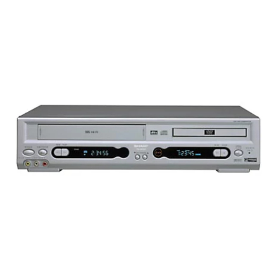
VCR/DVD COMBINATION MODEL
PLAY STOP
OPEN/
CLOSE
VCR DVD
(AV 1 )
MODELS
In the interests of user-safety (Required by safety regula-
tions in some countries) the set should be restored to its
original condition and only parts identical to those specified
be used.
QSURROUND
CONTENTS
1
DV-NC55U
DV-NC55C
DV-NC55M
This document has been published to be used for
after sales service only.
The contents are subject to change without notice.
DV-NC55U/C/M
S61U2DV-NC55U
Page
Table of Contents

Related Manuals for Sharp DV-NC55U


Summary of Contents for Sharp DV-NC55U
-
Page 1: Table Of Contents
DV-NC55U/C/M SERVICE MANUAL S61U2DV-NC55U VCR/DVD COMBINATION MODEL DV-NC55U PLAY PLAY STOP OPEN/ DV-NC55C POWER EJECT/ STOP CLOSE VCR DVD STANDBY (AV 1 ) CH(TRACKING) AV 2 IN VDEO L(MONO)-AUDIO-R DV-NC55M MODELS In the interests of user-safety (Required by safety regula-... -
Page 2: Important Service Notes
DV-NC55U/C/M 1. IMPORTANT SERVICE NOTES BEFORE RETURNING THE VCR/DVD COMBINA- etc.) and measure the AC voltage drop across the TION MODEL resistor. Reverse the AC plug on the set and repeat AC voltage measurements for each exposed part. Any reading of 0.45V rms (this corresponds to 0.3mA Before returning the video cassette recorder to the user, perform the following safety checks. - Page 3 DV-NC55U/C/M 1. NOTES DE SERVICE IMPORTANTES AVANT DE RENDRE LE VCR/DVD MAGNETOSCOPE pièces métalliques exposées ayant un parcours de retour au châssis (connexions d’antenne, coffret Avant de rendre le magnétoscope à l’utilisateur, effectuer métallique, tétes de vis, boutons et arbres de commande, etc.) et mesurer la chute de tension CA...
-
Page 4: Features
• S-VHS Quasi Playback • 19µ Clear Picture System (in EP mode) • Simple Recording Timer • Sharp Super Picture • Exact Rec/Tape Remaining Ë Ë Ë Ë Ë DVD • Plays DVD, CD (Digital Audio) discs as well as CD-R/CD-RW discs recorded in MP3 file format •... - Page 5 DV-NC55U/C/M Channel Coverage: VHF 2-13 UHF 14-69 CATV 1-125 Antenna Input: 75Ω Video Input: Input level: 0.5 to 2.0 Vp-p (75Ω) Video Output: Output level: 1.0 Vp-p (75Ω) Audio Output: Input level: –8 dBs (47kΩ) (0 dBs = 0.775 Vrms) Audio Output: Output level: –8 dBs (1kΩ)
-
Page 6: Part Names
DV-NC55U/C/M 4. PART NAMES... - Page 7 DV-NC55U/C/M...
- Page 8 DV-NC55U/C/M...
-
Page 9: Maintenance Check Items And Execution Time
DV-NC55U/C/M 5. MAINTENANCE CHECK ITEMS AND EXECUTION TIME MECHANICAL PARTS REGUIRING PERIODICAL INSPECTION Use the following table as a guide to maintain the mechanical parts in good operating condition. Maintained 1,000 hrs. 2,000 hrs. Parts Pickup Spindle Unit Sled Motor... -
Page 10: Disassembly Method
DV-NC55U/C/M 6. DISASSEMBLY METHOD 6-1. DISASSEMBLY METHOD 1) Removing the cabinet. (1) Remove the five screws 1 and 2. 2) Removing the front panel. (1) Remove the earth plate. (2) Remove the three screws 3. Shild Plate (3) Remove the three hooks 4. - Page 11 DV-NC55U/C/M (14)Remove the connector. (15)Remove the three screws g and h. Connector 5) Removing the cassette housing control/VTR mechanism. (1) Remove the two screws k. (2) Remove the two screws l. (3) Remove the one screw ;. (4) Remove the H/A shield case (upper) 6) Removing the terminal plate/VTR main PWB.
- Page 12 DV-NC55U/C/M 6-2. EXTENSION CABLE USE POINT (FOUR PLACES) Parts Code Price Code Name/Description QCNW-8570GEZZ Extension cable (FFC), 29pin 500mm DVD main CN801–I/F CN8202 QCNW-8571GEZZ Extension cable (wire), 9pin 500mm DVD main CN201–power P9001 QCNW-8601AJZZ Extension cable (FFC), 23pin I/F CN8203–DVD display CN5001...
-
Page 13
DV-NC55U/C/M 6-3. REPLACEMENT OF MAIN PARTS
1. Remove the mechanism with angle from the set (refer to 35 on page 140). 2. It is in such cases as the thin driver, and it is pushed in slowly, and a tray is drawn in the arrow direction the slide rack on the left of the base chassis. -
Page 14: Operation Of Pickup
DV-NC55U/C/M 7. OPERATION OF PICKUP 7-1. CIRCUIT CONFIGURATION OF PICKUP The pickup unit reads signals from the disk, and the flexible cable is connected to the board. The following signals flow through the cable. 7-3. POLARITIES OF SIGNAL 7-2. EQUIVALENT CIRCUIT OF PICKUP... -
Page 15: Adjustment, Replacement And Assembly Of Mechanical Units
DV-NC55U/C/M 8. ADJUSTMENT, REPLACEMENT AND ASSEMBLY OF MECHANICAL UNITS The explanation given below relates to the on-site general service (field service) but it does not relates to the adjustment and replacement which need high-grade equipment, jigs and skill. For example, the drum assembling, replacement and adjustment service must be performed by the person who have finished the technical courses. - Page 16 DV-NC55U/C/M 8-2. MAINTENANCE CHECK ITEMS AND EXECUTION TIME Perform the maintenance with the regular intervals as follows so as to maintain the quality of machine. 1000 1500 2000 Possible symptom Maintained Remarks hrs. hrs. hrs. hrs. encountered Parts Abnormal rotation or significant Guide roller ass’y...
- Page 17 DV-NC55U/C/M 8-3. FUNCTION OF MAJOR MECHANICAL PARTS (TOP VIEW) Function Function Full erase head Take-up main brake Supply pole base ass’y Pinch drive cam Tension arm A/C head ass’y Idler wheel ass’y Reverse guide lever ass’y Pinch drive lever ass’y...
- Page 18 DV-NC55U/C/M FUNCTION OF MAJOR MECHANICAL PARTS (BOTTOM VIEW) Function Function Upper and lower drum ass’y Reel belt Loading motor Clutch lever Drum drive motor Limiter pulley ass’y Take-up pole base ass’y Shifter Slow brake lever Master cam Capstan D.D. motor...
- Page 19 DV-NC55U/C/M 8-4. DISASSEMBLING THE MECHANISM/MAIN PWB ASSEMBLY 2. Removing the mechanism and cassette housing. 1. When removing the mechanism from the main PWB. Remove 2 screws 3 fixing the cassette housing to the Remove the PWB bottom plate 1 screw 1.
- Page 20 DV-NC55U/C/M 8-5. CARES WHEN REASSEMBLING cassette housing. (Conditions: When mechanism and PWB INSTALLING THE CASSETTE HOUSING have been installed) When the cassette housing is installed on the mechanism, the initial setting is essential condition. 2. Mechanical initial setting There are two initial setting methods, namely electrical and Feed the pulley feed gear of loading motor with screw mechanical.
- Page 21 DV-NC55U/C/M 8-6. REMOVING AND INSTALLING THE CAS- Notes: SETTE HOUSING 1. When fitting the S/E sensor holder to the cassette controller frame L/R, take care. • Removal 2. Misengagement of teeth of casecon drive gear and drive 1. In the cassette removing mode, remove the cassette.
- Page 22 DV-NC55U/C/M 8-8. REEL DISK REPLACEMENT AND HEIGHT Notes: CHECK 1. When installing the reel disk, take due care so that the • Removal tension band ass'y is not deformed and grease does no 1. Remove the cassette housing control assembly.
- Page 23 DV-NC55U/C/M 2. Whenever replacing the reel disk, perform the height Notes: checking and adjustment. 1. Hold the torque gauge by hand so that it is not moved. 2. Do not keep the reel disk in lock state. Do not allow long- time measurement.
- Page 24 DV-NC55U/C/M Notes: 8-12.CHECKING AND ADJUSTMENT OF TAKE- 1. Hold the torque gauge by hand so that it is not moved. UP TORQUE IN VIDEO SEARCH REWIND 2. Do not keep the reel disk in lock state. Do not allow long- MODE time measurement.
- Page 25 DV-NC55U/C/M 8-13.CHECKING THE VIDEO SEARCH REWIND BACK TENSION • Remove the cassette housing control assembly. • After short-circuiting between TP5102 and TP5103 Tension gauge Pinch roller provided goes left at VTR display PWB, plug in the 900 - 1,200gf power cord.
- Page 26 DV-NC55U/C/M • Checking Tension pole adjuster adjusting range 1. Set a cassette tape, push the REC button to place the unit in the SP record mode. Now check the tension pole Tension pole adjuster position. 2. Visually check to see if the right edge of the tension pole is within the 2.3 ±...
- Page 27 DV-NC55U/C/M • Adjustment • Checking the brake torque at the take-up side 1. If the indication of torque cassette meter is lower than the setting, shift the tension spring engagement to the part A. Torque gauge 2. If the indication of torque cassette meter is higher than the setting, shift the tension spring engagement to the part B.
- Page 28 DV-NC55U/C/M 3. Align the left end of gear of A/C head arm with the 8-18. REPLACEMENT OF A/C (AUDIO/CONTROL) punched mark of chassis, tentatively tighten the screws HEAD 1 and 2 so as to ensure smooth motion of A/C head 1.
- Page 29 DV-NC55U/C/M 8-19.A/C HEAD HEIGHT ROUGH ADJUSTMENT 8-20.HEIGHT ADJUSTMENT OF REVERSE GUIDE • Setting Azimuth screw 1. Adjust the height from the mechanism chassis to the reverse guide lower flange to 13.38 mm, using the reverse guide height adjustment jig, in tape loading state.
- Page 30 DV-NC55U/C/M Notes: 8-21. ADJUSTMENT OF TAPE DRIVE TRAIN 1. Previously set the tracking control in the center position, 1. Tape run rough adjustment and adjust the ATR signal waveform to maximum with X 1 Remove the cassette housing control assembly.
- Page 31 DV-NC55U/C/M 3 Next, press the tracking button (+), (–) and change the ATR signal waveform from max to min and from PB CHROMA min to max. At this time adjust the height of supply Signal and take-up side guide roller with the adjustment driver (JiGDRiVER-4) so that the ATR signal wave- form changes nearly parallel.
- Page 32 DV-NC55U/C/M 8-23. REPLACEMENT OF DRUM D.D. MOTOR 8-22.REPLACEMENT OF THE CAPSTAN D.D. 1. Set the ejection mode. (DIRECT DRIVE) MOTOR 2. Withdraw the main power plug from the socket. • Remove the mechanism from the main PWB (refer to 8- 4 item 1 When removing the mechanism from the main •...
- Page 33 DV-NC55U/C/M 8-24.REPLACING THE UPPER AND LOWER 8-25.ASSEMBLING OF PHASE MATCHING DRUM ASSEMBLY MECHANISM COMPONENTS • Assemble the phase matching mechanism compo- • Replacement (Perform in the numerical order) nents in the following order. 1 Remove the motor as stated in 8-23 D.D. motor replace- 1.
- Page 34 DV-NC55U/C/M 1Insert Reverse Guide Lever Ass’y Insert reverse guide lever ass'y 2 Insert pinch drive cam Align here. Turn the reverse guide lever assembly counterclockwise Fit the pinch drive cam so that the notch of pinch to the stopper. drive cam aligns with the dent of pinch drive lever assembly.
- Page 35 DV-NC55U/C/M 1. Make sure that the loading gear is at the Phase-Match- 8-26. INSTALLING THE SHIFTER ing point 1 as shown below. 2. Install, paying attention to insert point 5 and release point 3. Drum 3. For the phase matching at the insert point 1, see the Phase-Matching point 2 as shown below.
- Page 36 DV-NC55U/C/M 8-27.INSTALLING THE MASTER CAM (AT 8-28. REPLACEMENT OF LOADING MOTOR • Removal REAR SIDE OF MECHANISM CHASSIS) 1. Make sure beforehand that the shifter is at the point as shown below. 2. Place the master cam in the position as shown below.
- Page 37 DV-NC55U/C/M 8-29. ASSEMBLY OF CASSETTE HOUSING 1. Drive Gear and R Drive angle ass’y MSPRT0381AJFJ Apply grease Apply grease Apply grease Figure 8-48. 2. Synchro Gear, Drive Gear L and Drive Gear R LANGF9592AJFW Top surface should be free from scratches or soil.
-
Page 38: Test Mode
DV-NC55U/C/M 9. TEST MODE "NO DISC" state "F0" key input (Press the "play" key and the "stop" key for 5 seconds.) F0000000 00000000The preparation date display of the program... - Page 39 DV-NC55U/C/M From (1) "3" Key input DYNMIC TEST 30000000 00000000 Laser test mode "1" Key input The tray opens, the DVD laser is lit, LASER TEST spinning is performed and the sled moves to the outer periphery. 30000001 000000DD "1" Key input...
- Page 40 DV-NC55U/C/M From (2) Following playback, jump test mode "3" Key input PLAY TEST Load a disc after the tray is opened. 30000001 00000000 "Open/Close" Key input PLAY TEST Following playback state (~~~~~~~~ is a sector ID) DD000303 ~~~~~~~~ Pressing the keys on the remote control mentioned in the table below enables the test jump.
- Page 41 DV-NC55U/C/M...
- Page 42 DV-NC55U/C/M...
- Page 43 DV-NC55U/C/M...
- Page 44 DV-NC55U/C/M...
- Page 45 DV-NC55U/C/M...
- Page 46 DV-NC55U/C/M...
- Page 47 DV-NC55U/C/M...
- Page 48 DV-NC55U/C/M...
- Page 49 DV-NC55U/C/M...
- Page 50 DV-NC55U/C/M...
- Page 51 DV-NC55U/C/M...
-
Page 52: Ic Function List
DV-NC55U/C/M 11. IC FUNCTION LIST 11-1. IC301 TA1323F RF PROCESSOR Pin No. Terminal name Operation function Terminal DC Voltage(TYP.) Remarks – GND terminal. – P2TP TE+input (CD) P2TN TE–input (CD) LDO2 O Drive ouput 2 – MDI2 Monitor input 2 –... - Page 53 DV-NC55U/C/M Pin No. Terminal name Operation function Terminal DC Voltage(TYP.) Remarks Frequency adjustment When EQF is raised, shift to the high frequency side occurs. Adjusting range: GND - Vdd MDI1 Monitor input 1 – LDO1 O Drive output 1 –...
- Page 54 DV-NC55U/C/M 11-2. IC501 IX1689GE FLASH MEMORY Pin No. Symbol Type Name and function Byte selection address: When the device is in the x8 mode, the low or high order byte is Input selected. It is not used in the x16 mode.
- Page 55 DV-NC55U/C/M • Block Diagram 8-14 Output Output Input Input Buffer Buffer Buffer Buffer I/O Logic BYTE# DATA QUEUE REGISTER Register Register ESRs Data Comparator Input Buffer Y-DECODER Y GATING/SENSING RY/BY# ADDRESS QUEUE Program Erase LATCHES X-DECODER Voltage Switch ADDRESS COUNTER 11-3.
- Page 56 DV-NC55U/C/M 11-4. IC504 IX1687GE MICRO COM. • Block Diagram Port D Port E /IRQ7 /IRQ6 /IRQ5 /IRQ4 EXTAL XTAL STBY H8S/2000 CPU WDTOVF Interruption controller /Ø DMAC ROM * /HWR /LWR /LCAS/WAIT/BFEQO /BACK /BREQ /CS0 /CS1 /CS2 /CS3 /SCK1 /CAS...
- Page 57 DV-NC55U/C/M 11-5. IC508 IX1761GE TRACK BUFFER INTERFACE Pin No. Terminal name Operation function VDD1 Supply Digital power supply +3.3V HADR0 Input CPU Address bus HADR1 Input CPU Address bus HADR2 Input CPU Address bus HADR3 Input CPU Address bus HADR4...
- Page 58 DV-NC55U/C/M Pin No. Terminal name Operation function PDI[8] Output Input DVD/CD data PDI[7] Output Input DVD/CD data PDI[6] Output Input DVD/CD data PDI[5] Output Input DVD/CD data PDI[4] Output Input DVD/CD data PDI[3] Output Input DVD/CD data PDI[2] Output Input DVD/CD data...
- Page 59 DV-NC55U/C/M • Block Diagram 75 74 73 72 71 70 69 68 67 66 65 64 63 62 61 60 59 58 57 56 55 54 53 52 51 VDD1 5VBUFO[B] PSYCI 5VBUFI[B] Interface PDRQI 5VBUFO[A] PDCKI 5VBUFI[A] DVDREQ Error...
- Page 60 DV-NC55U/C/M 11-6. IC601 IX1720GE AV DECODER • Terminal description Name Type Description Host interface, CD-DSP interface, sub-code interface (32-pin) Reset input (active Low). When shifting from the assert state to deassert state, RESET# initialization process of this device is started.
- Page 61 DV-NC55U/C/M Name Type Description Host interface, CD-DSP interface, sub-code interface (32-pin)...continued Host ready output (active High). Use this signal when the stream is transferred via the host bus. External pull-up resistor is required. Prior to transfer of each packet (1 HRDY O(p.d.)
- Page 62 DV-NC55U/C/M Name Type Description Digital audio port (8-pin) Audio master clock I/O. Sampling frequency can be selected among 384fs, 256fs, AMCLK I/O(p.u.) 192fs, and 128fs (programmable). S/PDIF transmitter output. It can be connected to DAC as the fourth audio output S/PDIF (AOUT[3]) O(p.d.)
- Page 63 DV-NC55U/C/M • Block Diagram VDDA GNDP STNDBY# RAMDAT4 RAMDAT11 GNDA VDDP RESET# RAMDAT5 SCNENBL VDDP RAMDAT10 VCLKx2 RAMDAT6 GNDP GNDC RAMDAT9 TESTMODE VDDP VDDAAM AMCLK RAMDAT7 GNDAAM GNDP S/PDIF/AOUT3 RAMDAT8 GPIO VDDP PCLK VDDP GNDP AOUT0 AOUT1 RAMDQM AOUT2 VDDC...
- Page 64 DV-NC55U/C/M 11-7. IC602-3 IX3455CE 16M SDRAM Pin No. Terminal Name Name Input Function Clock The system clock input. All other inputs are referenced to the SDRAM on the rising edge of CLK. Clock Enable Controls internal clock signal and when deactivated, the SDRAM will be one of the states among power down, suspend or self refresh.
- Page 65 DV-NC55U/C/M 11-8. IC701 TC94A03F SERVO/DATA PROCESSOR Pin No. Terminal Name In/Output Operation function 3/5V system Remarks ASLCN Output Data slice negative pole output 3V system Analog output terminal ASLCO Output Analog data slice output 3V system Analog output terminal (Digital slice output enabled at differential input) DVSS –...
- Page 66 DV-NC55U/C/M Pin No. Terminal Name In/Output Operation function 3/5V system Remarks – – SMCK Output 22M system clock output 5V system VMCK Output Data output system (signal processing 5V system system) clock output VDD3 – 3.3V digital power supply –...
- Page 67 DV-NC55U/C/M Pin No. Terminal Name In/Output Operation function 3/5V system Remarks BD13 BD14 In/Output External RAM data I/O 5V system BD15 – – VDD3 – 3.3V digital power supply – PLCK In/Output PLL system clock I/O 3V system TESM5 –...
- Page 68 DV-NC55U/C/M Pin No. Terminal Name In/Output Operation function 3/5V system Remarks EXTAD Input General-purpose external ADC input 3V system Analog input terminal VREF – Reference power supply for analog system 3V system only: 1.65V Output Focus EQ output 3V system...
- Page 69 DV-NC55U/C/M 11-9. IC702 IX3420CE 4M EDO DRAM Terminal Terminal name Function 16-19, 22-26 Address inputs. Row address strobe. UCAS Column address strobe/upper byte control. LCAS Column address strobe/lower byte control. Write enable. Output enable. 2-5, 7-10 Data inputs/outputs. 31-34, 36-39 1, 6, 20 +3.3V power supply.
- Page 70 DV-NC55U/C/M 11-10. IC5001 PT6312LQ FL DRIVER Pin No. Terminal name Operation function SW1 to SW4 General purpose input pins DOUT Data output pin (N-Channel, Open-Drain) This pin outputs serial data at the falling edge of the shift clock (starting from the lower bit).
- Page 71 DV-NC55U/C/M 11-11. IC6001 PCM1737 AUDIO DAC Pin No. Terminal name Operation function LRCK LRCK clock input (fs) DATA Audio • Data input Bit clock input for data. CLKO System clock buffered output. SCLK System clock input. DGND – Digital ground.
- Page 72 DV-NC55U/C/M 11-12. IC7701 BA5984FP MOTOR DRIVER Pin No. Terminal name Operation function Pin No. Terminal name Operation function LD-FWD Loading driver FWD input terminal V04(+) Driver CH4 Negative output SL_IN(+) CH1 Former stage amplifier nonreverse input terminal V04(-) Driver CH4 Positive output...
- Page 73 DV-NC55U/C/M 11-13. IC8201 IX1757GE INTERFACE MICOM. • Terminal description Pin No. Terminal Name In/Output Operation function TRAY ACK(L) Input Input terminal of [TRAY ACK] from DVD microcomputer DVD LED(L) Output DVD LED control terminal It outputs [L] and is lit during DVD output.
- Page 74 DV-NC55U/C/M • Block Diagram...
- Page 75 DV-NC55U/C/M - M E M O -...
-
Page 76: Block Diagrams
DV-NC55U/C/M DV-NC55U/C/M 12. BLOCK DIAGRAMS 12-1. MAIN BLOCK DIAGRAM 76~77... - Page 77 DV-NC55U/C/M DV-NC55U/C/M 12-2. VTR SIGNAL FLOW BLOCK DIAGRAM 78~79...
- Page 78 DV-NC55U/C/M DV-NC55U/C/M 12-3. VTR SERVO BLOCK DIAGRAM 80~81...
- Page 79 DV-NC55U/C/M DV-NC55U/C/M 12-4. POWER BLOCK DIAGRAM 82~83...
-
Page 80: Schematic Diagrams
DV-NC55U/C/M DV-NC55U/C/M 13. SCHEMATIC DIAGRAMS 13-1. DVD MAIN (1) CIRCUIT SCHEMATIC DIAGRAM 84~85... - Page 81 DV-NC55U/C/M DV-NC55U/C/M 13-2. DVD MAIN (2) CIRCUIT SCHEMATIC DIAGRAM 86~87...
- Page 82 DV-NC55U/C/M 13-3. VTR DISPLAY CIRCUIT SCHEMATIC DIAGRAM...
- Page 83 DV-NC55U/C/M 13-4. DVD DISPLAY CIRCUIT SCHEMATIC DIAGRAM...
- Page 84 DV-NC55U/C/M DV-NC55U/C/M 13-5. AUDIO/VIDEO CIRCUIT SCHEMATIC DIAGRAM 90~91...
- Page 85 DV-NC55U/C/M DV-NC55U/C/M 13-6. POWER CIRCUIT SCHEMATIC DIAGRAM å AND SHADED COMPONENTS=SAFETY RELATED PARTS 92~93...
- Page 86 DV-NC55U/C/M DV-NC55U/C/M 13-7. INTERFACE CIRCUIT SCHEMATIC DIAGRAM 94~95...
- Page 87 DV-NC55U/C/M DV-NC55U/C/M 13-8. VTR MAIN (1) CIRCUIT SCHEMATIC DIAGRAM 96~97...
- Page 88 DV-NC55U/C/M DV-NC55U/C/M å AND SHADED COMPONENTS=SAFETY RELATED PARTS 13-9. VTR MAIN (2) CIRCUIT SCHEMATIC DIAGRAM å 98~99...
- Page 89 DV-NC55U/C/M DV-NC55U/C/M 13-10. VTR MAIN (3) CIRCUIT SCHEMATIC DIAGRAM 100~101...
-
Page 90: Printed Wiring Board Assemblies
DV-NC55U/C/M 14. PRINTED WIRING BOARD ASSEMBLIES DVD MAIN PWB Component Side SIDE A Q308 CN702 CN701 Q309 C213 TP831 TP318 C210 TP7705 TP7704 TP7703 TP7702 TP7701 TP7711 TP7710 TP7709 TP7708 TP7707 TP7706 TP320 TP322 R341 C309 C302 TP323 TP832 R342... - Page 91 DV-NC55U/C/M Wiring Side SIDE A...
- Page 92 DV-NC55U/C/M Component Side SIDE B CN302 R323 C707 R321 R315 R707 C305 R310 Q701 L702 C729 Q301 D301 C710 R728 C728 C705 C716 R304 C304 C706 R708 C709 TP712 C306 TP701 C737 C319 R738 R737 C738 R740 R739 C708 R742...
- Page 93 DV-NC55U/C/M Wiring Side SIDE B...
- Page 94 DV-NC55U/C/M VTR DISPLAY PWB Component Side SIDE A Wiring Side SIDE A Component Side SIDE B Wiring Side SIDE B...
- Page 95 DV-NC55U/C/M DVD DISPLAY PWB Component Side SIDE A Wiring Side SIDE A Component Side SIDE B Wiring Side SIDE B...
- Page 96 DV-NC55U/C/M AUDIO/VIDEO PWB Component Side SIDE A Wiring Side SIDE A...
- Page 97 DV-NC55U/C/M Component Side SIDE B Wiring Side SIDE B...
- Page 98 DV-NC55U/C/M POWER PWB Component Side SIDE A Wiring Side SIDE A...
- Page 99 DV-NC55U/C/M Component Side SIDE B Wiring Side SIDE B...
- Page 100 DV-NC55U/C/M INTERFACE PWB Component Side SIDE A Wiring Side SIDE A...
- Page 101 DV-NC55U/C/M Component Side SIDE B Wiring Side SIDE B...
- Page 102 DV-NC55U/C/M DV-NC55U/C/M VTR MAIN PWB Component Side SIDE A 114~115...
- Page 103 DV-NC55U/C/M DV-NC55U/C/M Wiring Side SIDE A 116~117...
- Page 104 DV-NC55U/C/M DV-NC55U/C/M Component Side SIDE B 118~119...
- Page 105 DV-NC55U/C/M DV-NC55U/C/M Wiring Side SIDE B 120~121...
- Page 106 DV-NC55U/C/M - M E M O -...
-
Page 107: Replacement Parts List
D301 VHDDAP222//-1 DAP222 " HOW TO ORDER REPLACEMENT PARTS " D501 VHDDAN222//-1 DAN222 PACKAGED CIRCUIT in USA: Contact your nearest SHARP Parts Distributor. For loca- X601 RCRSC0039GEZZY Crystal, CRSC0039GE tion of SHARP Parts Distributor, Call Toll-free 1-IBE800-SHARP FILTER FL501 RFiLC0207GEZZ... - Page 108 DV-NC55U/C/M Ref. No. Part No. Description Code Ref. No. Part No. Description Code DUNTK6054TE6D C732 VCKYCY1CB104K 16V Ceramic DVD MAIN PWB UNIT(Continued) C733 VCKYCY1CB104K 16V Ceramic C734 VCCCCY1HH561J 560p 50V Ceramic C517 VCKYCY1HB103K 0.01 50V Ceramic C735 VCKYCY1HB103K 0.01 50V Ceramic...
- Page 109 DV-NC55U/C/M Ref. No. Part No. Description Code Ref. No. Part No. Description Code DUNTK6054TE6D R736 VRS-CY1JF103J 10k 1/16W Metal Oxide AA DVD MAIN PWB UNIT(Continued) R737 VRS-CY1JF000J 1/16W Metal Oxide AA R738 VRS-CY1JF333F 33k 1/16W Metal Oxide AA R533 VRS-CY1JF103J...
- Page 110 DV-NC55U/C/M Ref. No. Part No. Description Code Ref. No. Part No. Description Code DUNTK6054TE6D J5102 QJAKE0257GEZZ Jack, AUDIO IN(L) DVD MAIN PWB UNIT(Continued) J5103 QJAKE0180CEZZ Jack, AUDIO IN(R) RMC5101 RRMCU0085GEZZ Remote Receiver R814 RBLN-0076TAZZ Balun, BLN-0076TA R815 RBLN-0076TAZZ Balun, BLN-0076TA...
- Page 111 DV-NC55U/C/M Ref. No. Part No. Description Code Ref. No. Part No. Description Code DUNTK6058TEV2 C6051 VCKYCY1EB103K 0.01 25V Ceramic AUDIO/VIDEO PWB UNIT(Continued) C6052 VCEA9M1CW476M 16V Electrolytic C6053 VCEA9M1CW107M 16V Electrolytic C6054 VCEA9M1CW106M 16V Electrolytic Q2004 VS2SC3052EF-1 2SC3052EF C6055 VCEA9M1CW106M 16V Electrolytic...
- Page 112 DV-NC55U/C/M Ref. No. Part No. Description Code Ref. No. Part No. Description Code DDUNTK6058TEV2 å T901 RTRNW0022AJZZ Transformer AUDIO/VIDEO PWB UNIT(Continued) CAPACITORS å C901 R6071 VRS-CY1JF821J 820 1/16W Metal Oxide AA RC-FZ036SCEZZ 250V Ceramic R6072 VRS-CY1JF821J 820 1/16W Metal Oxide AA å...
- Page 113 DV-NC55U/C/M Ref. No. Part No. Description Code Ref. No. Part No. Description Code DUNTK6059TEV2 D6003 VHD1SS119//-1 1SS119 POWER PWB UNIT(Continued) D6006 VHD1SS119//-1 1SS119 D6007 VHD1SS119//-1 1SS119 R9070 VRS-CY1JF123J 12k 1/16W Metal Oxide AA D6101 RH-EX0609GEZZ Zener, EX0609GE D8201 VHD1SS119//-1 1SS119...
- Page 114 DV-NC55U/C/M Ref. No. Part No. Description Code Ref. No. Part No. Description Code DUNTK6060TEV2 Q1602 VS2SC3203Y/-1 2SC3203Y INTERFACE PWB UNIT(Continued) Q1603 VS2SC3052EF-1 2SC3052EF Q1604 VS2SC2712Y/-1 2SC2712Y R6050 VRS-CY1JF473J 47k 1/16W Metal Oxide AA Q1605 VS2SC2712Y/-1 2SC2712Y R6051 VRS-CY1JF473J 47k 1/16W Metal Oxide AA...
- Page 115 DV-NC55U/C/M Ref. No. Part No. Description Code Ref. No. Part No. Description Code DUNTK6068TEV2 C1507 VCKYCY1CF104Z 16V Ceramic VTR MAIN PWB UNIT(Continued) C1508 VCEA9M1HW475M 50V Electrolytic C1509 VCKYCY1HF103Z 0.01 50V Ceramic C1160 VCEA9M1HW225M 50V Electrolytic C1512 VCKYCY1HF103Z 0.01 50V Ceramic...
- Page 116 DV-NC55U/C/M Ref. No. Part No. Description Code Ref. No. Part No. Description Code DUNTK6068TEV2 C1953 VCEA9M1CW106M 16V Electrolytic VTR MAIN PWB UNIT(Continued) C1954 VCEA9M1HW105M 50V Electrolytic C1971 VCEA9M0JW226M 6.3V Electrolytic C1708 VCCCCY1HH150J 50V Ceramic C1981 VCEA9M0JW476M 6.3V Electrolytic C1711 VCKYCY1HB102K...
- Page 117 DV-NC55U/C/M Ref. No. Part No. Description Code Ref. No. Part No. Description Code DUNTK6068TEV2 R1752 VRD-RA2BE123J 12k 1/8W Carbon VTR MAIN PWB UNIT(Continued) R1753 VRD-RA2BE102J 1/8W Carbon R1754 VRS-CY1JF102J 1/16W Metal Oxide AA R1666 VRS-CY1JF682J 6.8k 1/16W Metal Oxide AA...
- Page 118 DV-NC55U/C/M Ref. No. Part No. Description Code Ref. No. Part No. Description Code DUNTK6068TEV2 SUPPLIED ACCESSORIES VTR MAIN PWB UNIT(Continued) QCNW-8387AJZZ 75 Ohm Coaxial Cable BALUNES QCNW-8549AJZZ VIDEO/AUDIO Cable FB1101 RBLN-0088AJZZY Balun, BLN-0088AJ RRMCG1293AJSA Remote Control Unit FB1102 RBLN-0088AJZZY Balun, BLN-0088AJ...
- Page 119 DV-NC55U/C/M Ref. No. Part No. Description Code Ref. No. Part No. Description Code MECHANISM PARTS (VTR PART) SCREW, NUTS AND WASHERS LBNDK1011AJZZ Tension Band Ass’y XBPSD26P08000 Screw 2.6P+8S A/C Head AA LBOSZ1007AJZZ Tension Arm boss LX-HZ3082GEZZ WSW 2.6+6 LBOSZ1006AJZZ Cassette Stay L...
- Page 120 DV-NC55U/C/M Ref. No. Part No. Description Code Ref. No. Part No. Description Code CABINET PARTS FRONT PANEL PARTS CCABA3154TEV1 Top Cabinet Ass'y CPNLC2931TEV1 Front Panel Ass'y CPNLC2931TEV1 KS Panel HDECQ2351AJSB Decoration Plate(Left) CDECQ2350TEV2 Tray Decoration Cover HDECQ2401AJSA Decoration Plate(Right) TLABM4553AJZZ...
- Page 121 DV-NC55U/C/M MECHANISM EXPLODED VIEW (DVD PART) Ref. No. Part No. Description Code Ref. No. Part No. Description Code Dry Coating Dry Coating Dry Coating Dry Coating Grease Grease 401-11 401-13 401-10 Grease 401-12 Grease 401-4 401-3 401-2 Grease 401-5 å Caution...
- Page 122 DV-NC55U/C/M MECHANISM EXPLODED VIEW (VTR PART) Ref. No. Part No. Description Code Ref. No. Part No. Description Code...
- Page 123 DV-NC55U/C/M CASSETTE HOUSING CONTROL EXPLODED VIEW Ref. No. Part No. Description Code Ref. No. Part No. Description Code...
- Page 124 DV-NC55U/C/M CABINET EXPLODED VIEW Ref. No. Part No. Description Code Ref. No. Part No. Description Code...
- Page 125 DV-NC55U/C/M FRONT PANEL EXPLODED VIEW Ref. No. Part No. Description Code Ref. No. Part No. Description Code...
-
Page 126: Packing Of The Set
DV-NC55U/C/M 16. PACKING OF THE SET Ref. No. Part No. Description Code Ref. No. Part No. Description Code TGAN-3324AJZZ(DV-NC55U) (Guarantee Card) TLSTS0022TAZZ(DV-NC55C) (Ass List) SSAKA0001AJZZ RRMCG1293AJSA TiNS-4012AJZZ(DV-NC55U) (DV-NC55U/C) (Remote Control unit) TiNS-4034AJZZ(DV-NC55C) (Polyethylene Bag) (Operation Manual) SPAKP0209AJZZ (Wrapping Paper) QCNW-8387AJZZ... - Page 127 DV-NC55U/C/M Ref. No. Part No. Description Code Ref. No. Part No. Description Code...
- Page 128 Part No. Description Code © COPYRIGHT 2001 BY SHARP CORPORATION ALL RIGHTS RESERVED. No part of this publication may be reproduced, stored in a retrieval system, or transmitted in any form or by any means, electronic, mechanical, photocopying, recording, or otherwise, without prior written permission of the publisher.