Toshiba VF-S15 Instruction Manual
Industrial inverter for 3-phase induction motors
Hide thumbs
Also See for VF-S15:
- Instruction manual (394 pages) ,
- Quick start manual (90 pages) ,
- Function manual (80 pages)
Table of Contents
Quick Links
Industrial Inverter
(For 3-phase induction motors)
Instruction Manual
3-phase 240V class 0.4 to 15kW
1-phase 240V class 0.2 to 2.2kW
3-phase 500V class 0.4 to 15kW
1. Make sure that this instruction manual is delivered to the
end user of the inverter unit.
2. Read this manual before installing or operating the inverter
unit, and store it in a safe place for reference.
NOTICE
E6581611
S
I
Safety
precautions
Contents
1
Read first
2
Connection
3
Operations
4
Setting
parameters
5
Main
parameters
6
Other
parameters
7
Operation
with external
signal
8
Monitoring the
operation status
9
Measures
to satisfy the
standards
10 10
Peripheral
devices
11 11
Table of
parameters
and data
12 12
Specifications
13 13
Before making
a service call
14 14
Inspection and
maintenance
15 15
Warranty
16 16
Disposal of the
inverter
Table of Contents

Related Manuals for Toshiba VF-S15


Summary of Contents for Toshiba VF-S15
-
Page 1: Industrial Inverter
E6581611 Safety precautions Contents Industrial Inverter Read first (For 3-phase induction motors) Connection Operations Instruction Manual Setting parameters Main parameters Other parameters Operationwith external signal Monitoring the operation status Measures to satisfy the standards 3-phase 240V class 0.4 to 15kW 10 10 Peripheral 1-phase 240V class 0.2 to 2.2kW... -
Page 2: Operations
E6581611 Safety precautions The items described in these instructions and on the inverter itself are very important so that you can use safely the inverter, prevent injury to yourself and other people around you as well as to prevent damage to property in the area. -
Page 3: Safety Precautions
If the inverter begins to emit smoke or an unusual odor, or unusual sounds, immediately turn the power off. Continuous use of the inverter in such a state may cause fire. Call your Toshiba distributor Mandatory for repairs. -
Page 4: Instruction Manual
Do not install or operate the inverter if it is damaged or any component is missing. 1.4.4 This can result in electric shock or fire. Call your Toshiba distributor for repairs. Do not place any inflammable objects near the inverter. - Page 5 E6581611 Reference Caution section When removing and installing the terminal cover with a screwdriver, be sure not to scratch 1.3.2 your hand as these results in injury. 1.3.2 Pressing too hard on the screwdriver may scratch the inverter. 1.3.2 ...
- Page 6 E6581611 Reference Warning section Ground must be connected securely. If the ground is not securely connected, it could lead to electric shock or fire. Be Grounded Reference Caution section Do not attach devices with built-in capacitors (such as noise filters or surge absorbers) to the output (motor side) terminals.
- Page 7 E6581611 Reference Caution section Use an inverter that conforms to the specifications of power supply and three-phase 1.4.1 induction motor being operated. If the inverter being used does not conform to those specifications, not only will the three-phase induction motor not rotate correctly, but it may cause serious accidents through overheating and fire.
-
Page 8: Other
Do not replace parts. 14.2 This could be a cause of electric shock, fire and bodily injury. To replace parts, call your Toshiba distributor. Prohibited The equipment must be inspected daily. If the equipment is not inspected and maintained, errors and malfunctions may not be discovered and that could result in accidents. -
Page 9: Table Of Contents
Description of terminals ............................. B-6 3. Operations ..................................C-1 How to Set the Setup Menu..........................C-2 Simplified Operation of the VF-S15 ........................C-4 How to operate the VF- S15 ..........................C-9 4. Setting parameters ................................ D-1 Setting and Display Modes ..........................D-1 How to set parameters............................ - Page 10 E6581611 Manual torque boost - increasing torque boost at low speeds ................F-24 Signal output ..............................F-25 Input signal selection............................F-28 Terminal function selection..........................F-31 Basic parameters 2 ............................F-33 V/f 5-point setting ...............................F-35 6.10 Frequency priority selection ..........................F-35 6.11 Operation frequency............................F-44 6.12 DC braking .................................F-46 6.13 Stop at lower-limit frequency operation (sleep function)..................F-48 6.14...
- Page 11 E6581611 8. Monitoring the operation status............................H-1 Flow of status monitor mode..........................H-1 Status monitor mode............................H-2 Display of trip information ..........................H-6 9. Measures to satisfy the standards ..........................I-1 How to cope with the CE Marking Directive....................... I-1 Compliance with UL Standard and CSA Standard .....................
- Page 12 E6581611 15. Warranty..................................O-1 16. Disposal of the inverter ..............................P-1...
-
Page 13: Read First
E6581611 1. Read first Check product purchase Before using the product you have purchased, check to make sure that it is exactly what you ordered. Caution Use an inverter that conforms to the specifications of power supply and three-phase induction motor being used. -
Page 14: Contents Of The Product
W: W orl d m odel 002 : 0.2kW TOSVERT 2 : 200V to 240V EMC filter None: Japanese model VF-S15 series 004 : 0.4kW 4 : 380V to 500V M: Built-in basic filter 007 : 0.75kW 015 : 1.5kW 022 : 2.2kW... -
Page 15: Names And Functions
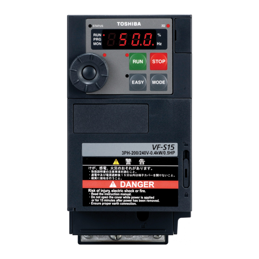
E6581611 Names and functions 1.3.1 Outside view Charge lamp Indicates there is a high voltage still in the inverter. STATUS lamp Do not open the terminal block cover when this lamp is lit because it is dangerous. Lights and blinks when ®... - Page 16 E6581611 Example of the protective label on the top of the inverter [Opening the cover] Insert a small screw driver and slide the door lock to upside for unlock. (Slide it to downside for lock.) About the monitor display The LED on the operation panel uses the following symbols to indicate parameters and operations. LED display (numbers) LED display (letters)
-
Page 17: Operation Panel
E6581611 [Operation panel] RUN lamp % lamp Hz lamp Lit when a frequency is Displayed numbers are Displayed numbers are not output with the ON in Hertz. in %. run command. This lamp blinks when operation RUN key starts. Pressing this key while the RUN key lamp is on PRG lamp starts operation. - Page 18 E6581611 1.3.2 Opening terminal cover and terminal block Warning Never touch the internal connector while the upper cover of control panel is opened. There is a risk of electrical shock because it carries a high voltage. Prohibited Caution When removing and mounting the terminal cover or the terminal block with a screwdriver, be sure not to scratch your hand as these results in injury.
- Page 19 E6581611 (1) Removing the outside terminal block cover (VFS15-2004PM-W to 2007PM-W, VFS15S-2002PL-W to 2007PL-W) Press in on the screwdriver. Insert a screwdriver or other thin object into the hole indicated with the mark. While pressing on the screwdriver, rotate the Pull the terminal cover up at an angle.
- Page 20 E6581611 (2) Removing the inside terminal block cover (VFS15-2004PM-W to 2007PM-W, VFS15S-2002PL-W to 2007PL-W) The finger is put on to the tab part of the While pressing on the screwdriver, rotate the terminal block cover. terminal cover downward to remove it. Pull the terminal cover up at an angle.
- Page 21 E6581611 (3) Removing the outside terminal block cover (VFS15-2015PM-W to 2037PM-W, VFS15S-2015PL-W, 2022PL-W, VFS15-4004PL-W to 4037PL-W) Insert a screwdriver or other thin object into the Press in on the screwdriver. hole indicated with the mark. While pressing on the screwdriver, sidles the terminal cover downward to remove it.
- Page 22 E6581611 (4) Removing the inside terminal block cover (VFS15-2015PM-W to 2037PM-W, VFS15S-2015PL-W, 2022PL-W, VFS15-4004PL-W to 4015PL-W) The finger is put on to the tab part of the While pressing on the screwdriver, rotate the terminal block cover. terminal cover downward to remove it. Pull the terminal cover up at an angle.
- Page 23 E6581611 (5) Removing the inside terminal block cover (VFS15-4022PL-W, 4037PL-W) The finger is put on to the tab part of the While pressing on the screwdriver, rotate the terminal block cover. terminal cover downward to remove it. Pull the terminal cover up at an angle. ★...
- Page 24 E6581611 (6) Removing the power terminal cover (VFS15-2055PM-W to 2150PM-W, VFS15-4055PL-W to 4150PL-W) Insert a screwdriver or other thin object into the Press in on the screwdriver. hole indicated with the mark. While pressing on the screwdriver, slide the ★ After wiring is complete, be sure to restore the terminal cover downward to remove it.
- Page 25 E6581611 1.3.3 Power circuit and control circuit terminal blocks 1) Power circuit terminal In case of the lug connector, cover the lug connector with insulated tube, or use the insulated lug connector. Use a plus or minus screwdriver to loose or tighten screws. Screw size Tightening torque M3.5 screw...
- Page 26 E6581611 VFS15-2015PM-W, 2022PM-W M4 screw Shorting-bar Grounding terminal Grounding terminal (M4 screw) (M4 screw) Grounding terminal For EMC plate (M5 screw) VFS15-2037PM-W M4 screw Shorting-bar Grounding terminal For EMC plate (M5 screw) Note1) Bend the clips on the wiring port of the terminal cover to connect the PB, PO, PA/+, and PC/- terminals. Note2) Be careful to insert all wires into the cage of terminal block.
- Page 27 E6581611 VFS15S-2002PL-W to 2007PL-W Grounding capacitor switch Shorting-bar Grounding terminal Grounding terminal (M4 screw) (M4 screw) Grounding terminal (M5 screw) For EMC plate VFS15S-2015PL-W, 2022PL-W M4 screw Grounding capacitor switch Shorting-bar Grounding terminal Grounding terminal (M4 screw) (M4 screw) Grounding terminal (M5 screw) For EMC plate Note1) Bend the clips on the wiring port of the terminal cover to connect the PB, PO, PA/+, and PC/- terminals.
- Page 28 E6581611 VFS15-4004PL-W to 4015PL-W Shorting-bar Grounding capacitor switch M4 screw Grounding terminal (M5 screw) For EMC plate VFS15-4022PL-W, 4037PL-W Grounding capacitor switch M4 screw Shorting-bar Grounding terminal (M5 screw) For EMC plate Note1) Bend the clips on the wiring port of the terminal cover to connect the PB, PO, PA/+, and PC/- terminals. Note2) Be careful to insert all wires into the cage of terminal block.
- Page 29 E6581611 VFS15-2055PM-W, 2075PM-W VFS15-4055PL-W, 4075PL-W Grounding capacitor switch (4055PL-W, 4075PL-W only) M5 screw Shorting-bar Grounding terminal (M5 screw) Grounding terminal (M5 screw) For EMC plate VFS15-2110PM-W, 2150PM-W M6 screw Shorting-bar Grounding terminal Grounding terminal (M5 screw) (M5 screw) For EMC plate Note1) Bend the clips on the wiring port of the terminal cover to connect the PB, PO, PA/+, and PC/- terminals.
- Page 30 E6581611 VFS15-4110PL-W, 4150PL-W Grounding capacitor switch M5 screw Shorting-bar Grounding terminal (M5 screw) Grounding terminal (M5 screw) For EMC plate Note1) Bend the clips on the wiring port of the terminal cover to connect the PB, PO, PA/+, and PC/- terminals. Note2) Be careful to insert all wires into the cage of terminal block.
- Page 31 E6581611 2) Grounding capacitor switch Single-phase 240V model and three-phase 500V model have a built-in high-attenuation noise filter and is grounded via a capacitor. A switch makes for easy switching to reduce leakage current from the inverter and the load on the capacitor.
- Page 32 E6581611 3) Control circuit terminal block The control circuit terminal block is common to all equipment. VIB CC VIC S3 FM FLA FLB FLC RY RC SINK SOURCE OUT P24 F R CC +SU +24 Screw for removable control terminal block RS485 connector RES S1 S2 Recommended...
-
Page 33: Notes On The Application
E6581611 Notes on the application 1.4.1 Motors When this inverter and the motor are used in conjunction, pay attention to the following items. Caution Use an inverter that conforms to the specifications of power supply and three-phase induction motor being operated. If the inverter being used does not conform to those specifications, not only will the three-phase induction motor not rotate correctly, but it may cause serious accidents through overheating Mandatory and fire. - Page 34 E6581611 Low loads and low inertia loads The motor may demonstrate instability such as abnormal vibrations or overcurrent trips at light loads of 5% or under of the load percentage, or when the load's inertia moment is extremely small. If that happens reduce the carrier frequency.
- Page 35 E6581611 Motors with a brake When motors with a brake are directly connected to the inverter's output, the brake cannot be released at startup because of low voltage. Wire the brake circuit separately from the main circuit. 3-phase FLB FLC S2 (ST) power source Circuit diagram 1...
- Page 36 E6581611 1.4.2 Inverters Protecting inverters from overcurrent The inverter has an overcurrent protection function. The programmed current level is set to the inverter's maximum applicable motor. If the motor used has a small capacity, the overcurrent level and the electronic thermal protection must be readjusted. If adjustment is necessary, refer to section 5.6, and make adjustments as directed.
- Page 37 E6581611 Circuit breaking when two or more inverters are used on the same power line MCCB1 MCCB2 (circuit breaking fuse) INV1 MCCB3 INV2 MCCB: Molded-case circuit breaker MCCBn1 INVn Breaking of selected inverter There is no fuse in the inverter's main circuit. Thus, as the diagram above shows, when more than one inverter is used on the same power line, you must select interrupting characteristics so that only MCCB2 to MCCBn+1 will trip and the MCCB1 will not trip when a short occurs in the inverter (INV1).
- Page 38 E6581611 1.4.3 What to do about the leakage current Caution The leakage current through the input/output power cables of inverter and capacitance of motor may affect to peripheral devices. The value of leakage current is increased under the condition of the PWM carrier frequency and the Mandatory length of the input/output power cables.
- Page 39 E6581611 (2) Influence of leakage current across lines Thermal relays Inverter Power supply Leakage current path across wires Thermal relays The high frequency component of current leaking into electrostatic capacity between inverter out- put wires will increase the effective current values and make externally connected thermal relays operate improperly.
-
Page 40: Installation Environment
E6581611 Remedies: 1. Use a meter output terminal in the inverter control circuit. The load current can be output on the meter output terminal (FM). If the meter is connected, use an ammeter of 1mAdc full scale or a voltmeter of 10V full scale. 0-20mAdc (4-20mAdc) can be also output. - Page 41 If the inverter is installed in a location that is subject to vibration, anti-vibration measures are required. Please consult with Toshiba about these measures. If the inverter is installed near any of the equipment listed below, provide measures to insure against errors in operation.
- Page 42 Warning Do not install or operate the inverter if it is damaged or any component is missing. This can result in electric shock or fire. Call your Toshiba distributor for repairs. Prohibited Mount the inverter on a metal plate.
- Page 43 E6581611 The space shown in the diagram is the minimum allowable space. Because air cooled equipment has cooling fans built in on the top or bottom surfaces, make the space on top and bottom as large as possible to allow for air passage.
- Page 44 E6581611 Panel designing taking into consideration the effects of noise The inverter generates high frequency noise. When designing the control panel setup, consideration must be given to that noise. Examples of measures are given below. Wire so that the main circuit wires and the control circuit wires are separated. Do not place them in the same conduit, do not run them parallel, and do not bundle them.
- Page 45 E6581611 Installing more than one unit in a cabinet When two or more inverters are installed in one cabinet, pay attention to the followings. Inverters may be installed side by side with each other with no space left between them. When installing inverters side by side, remove the protective label on the top of the inverter.
-
Page 46: Connection
2. Connection Warning Never disassemble, modify or repair. This can result in electric shock, fire and injury. Call your Toshiba distributor for repairs. Disassembly prohibited Do not stick your fingers into openings such as cable wiring holes and cooling fan covers. - Page 47 E6581611 Warning Ground must be connected securely. If the ground is not securely connected, it could lead to electric shock or fire. Be Grounded Caution Do not attach devices with built-in capacitors (such as noise filters or surge absorber) to the output (motor side) terminal.
-
Page 48: Standard Connections
E6581611 Standard connections Warning Do not connect input power to the output (motor side) terminals (U/T1, V/T2, W/T3). Connecting input power to the output could destroy the inverter or cause a fire. Do not insert a braking resistor between DC terminals (between PA/+ and PC/- or PO and PC/-). It could cause a fire. -
Page 49: Signal Output
3ph-500V class: three-phase 380-500V -50/60Hz Control power supply Forward run command Single MCCB(2P) Control phase R/L1 Reverse run command VF-S15 circuit Power S/L2/N Reset supply Preset-speed command 1 Preset-speed command 2 Protective function activation output Preset-speed command 3 *1: The T/L3 terminal is not provided for... -
Page 50: Standard Connection Diagram
T/L3 W/T3 3ph-500V class: three-phase 380-500V -50/60Hz Control power MCCB(2P) supply Single R/L1 Forward run command phase Control VF-S15 circuit Power S/L2/N Reverse run command supply Reset Preset-speed command 1 Protective function Preset-speed command 2 activation output Preset-speed command 3... -
Page 51: Description Of Terminals
E6581611 Description of terminals 2.3.1 Power circuit terminals Connections with peripheral equipment Molded-case Magnetic Input AC noise circuit braker contactor reactor reduction filter Motor U/T1 Inverter R/L1 Power S/L2 V/T2 supply W/T3 T/L3 Zero-phase PA/+ reactor Braking resistor Note 1: The T/L3 terminal is not provided for any single-phase models. So if you are using single-phase models, use the R/L1 and S/L2/N terminals to connect power cables. -
Page 52: Operations
E6581611 2.3.2 Control circuit terminals The control circuit terminal block is common to all equipment. Regarding to the function and specification of each terminal, please refer to the following table. Refer to section 1.3.3.3) about the arrangement of control circuit terminals. Control circuit terminals Terminal Input /... - Page 53 E6581611 Terminal Input / Electrical Function Inverter internal circuits symbol output specifications Common Control circuit's equipotential terminal to Input / (3 terminals) output +24V 10Vdc Voltage (permissible load Output Analog power supply output Regulator current: 10mAdc) Multifunction programmable analog input. Default setting: 0-10Vdc (1/1000 resolution) and 0-60Hz (0-50Hz) 10Vdc...
- Page 54 E6581611 Terminal Input / Electrical Function Inverter internal circuits symbol output specifications 1mAdc full-scale ammeter or QS60T(option) Multifunction programmable analog 0-20mA (4-20mA) – output. Default setting: output frequency. DC ammeter +24V The function can be changed to ammeter, Permissible load +24V Voltage Output...
- Page 55 E6581611 Terminal Input / Electrical Function Inverter internal circuits symbol output specifications Multifunction programmable open Open collector collector output. Default setting detect output 24Vdc-100mA and output speed reach signal. Multifunction output terminals to which To output pulse two different functions can be assigned. trains, The NO terminal is an equipotential a current of 10mA...
- Page 56 E6581611 SINK (Negative) logic/SOURCE (Positive) logic (When the inverter's internal power supply is used) Current flowing out turns control input terminals on. These are called sink logic terminals. The general used method in Europe is source logic in which current flowing into the input terminal turns it Sink logic is sometimes referred to as negative logic, and source logic is referred to as positive logic.
-
Page 57
E6581611 SINK (Negative) logic (When an external power supply is used) The P24 terminal is used to connect to an external power supply or to separate a terminal from other input or output terminals.
Sink (Negative) logic Slide switch SW1 : PLC side Input... - Page 58 E6581611 Switching of slide switch Refer to section 1.3.3 3) about location of slide switch. (1) Switching of sink/source logic: SW1 (Default setting : PLC side) Setting of sink/source logic for F, R, RES, S1, S2, and S3 terminals are switched by slide switch SW1. When an external power supply is used for sink logic, set the slide switch SW1 to PLC side.
-
Page 59: Operations
Continuous use of the inverter in such a state may cause fire. Call your Toshiba distributor for repairs. Always turn the power off if the inverter is not used for long periods of time since there is a possibility of malfunction caused by leaks, dust and other material. -
Page 60: How To Set The Setup Menu
Toshiba distributer.) Each setup menu automatically sets all parameters relating to the base frequency and the base frequency voltage of the motor connected. - Page 61 E6581611 Values set by each setup parameter asia (Mainly in Asia, Title Function (Mainly in (Mainly in (Mainly in Oceania) Europe) North America) Japan) Note 1) ul/vl/170/ f204 /f213 / 50.0(Hz) 60.0(Hz) 50.0(Hz) Frequency 60.0(Hz) f219 /f330 / f367 /f814 Base 240V...
-
Page 62: Simplified Operation Of The Vf-S15
E6581611 Simplified Operation of the VF-S15 Operation command and Operation frequency command are necessary to operate the inverter. Operation method and operation frequency setting can be selected from the following. At default setting, the inverter runs and stops with RUN/STOP key on the panel keypad, and frequency can be set with the setting dial. - Page 63 E6581611 3.2.1 How to run and stop [Example of setting procedure] Panel operation LED display Operation Displays the output frequency (operation stopped). (When standard monitor display selection f710=0 [output frequency]) Displays the first basic parameter [History (auh)]. MODE Turn the setting dial, and select "cmod".
- Page 64 E6581611 (3) Coast stop Coast stop Assign parameters as described below in case of Motor Coast stop. Inverter will display off at Coast stop. speed 1) Assign "6 (ST)" to an input terminal. Set parameter =. Open the ST-CC for coast stop(see the F-CC status described on the right).
- Page 65 E6581611 3.2.2 How to set the frequency [Example of fmod setting procedure] fmod=1: Setting the frequency by the terminal VIA Panel operation LED display Operation Displays the output frequency (operation stopped). 00 (When standard monitor display selection f710=0 [output frequency]) MODE Displays the first basic parameter [History (auh)].
- Page 66 E6581611 (2) Setting of frequency using external signals to terminal block (=, or) ⇒ Refer to section 7.3 for details. (3) Switching two frequency commands ⇒ Refer to section 5.8 for details.
-
Page 67: How To Operate The Vf-S15
E6581611 How to operate the VF-S15 Overview of how to operate the inverter with simple examples Operation Command: Panel Operation Ex.1 Frequency Command: Setting Dial 1 Wiring PC/- PA/+ Motor MCCB U/T1 R/L1 S/L2 V/T2 W/T3 T/L3 Operation panel Parameter setting (default setting) - Page 68 E6581611 Operation Command : Panel Operation Ex.2 Frequency Command: Setting Dial 2 Wiring PC/- PA/+ Motor MCCB R/L1 U/T1 S/L2 V/T2 T/L3 W/T3 Operation panel Parameter setting Title Function Setting value Command mode selection Frequency setting mode selection 1 ...
- Page 69 E6581611 Operation Command: External Signal Ex.3 Frequency Command: Setting Dial Wiring PC/- PA/+ Motor MCCB R/L1 U/T1 S/L2 V/T2 W/T3 T/L3 Forward signal Operation panel Reverse signal Common Parameter setting Title Function Setting value Command mode selection Frequency setting mode selection 1 0 or 3 ...
- Page 70 E6581611 Operation Command: External Signal Ex.4 Frequency Command: External Analog Signal Wiring PA/+ PC/- Motor MCCB R/L1 U/T1 S/L2 V/T2 T/L3 W/T3 Forward signal Reverse signal Common Current signal: VIB PP 4(0)20mA Voltage signal: 0+10V (or -10+10Vdc) External potentiometer (Otherwise, input voltage signal between the terminals VIA-CC.) Parameter setting Title Function...
-
Page 71: Setting Parameters
E6581611 4. Setting parameters Setting and Display Modes This inverter has the following three display modes. Standard monitor mode The standard inverter mode. This mode is enabled when inverter power goes on. This mode is for monitoring the output frequency and setting the frequency reference value. If also displays information about status alarms during running and trips. - Page 72 E6581611 Status monitor mode The mode for monitoring all inverter status. Allows monitoring of frequency command value, output current/voltage and terminal information. Refer to chapter 8. The inverter can be moved through each of the modes by pressing the MODE key. Frequency setting method ...
-
Page 73: How To Set Parameters
E6581611 How to set parameters There are two types of setting monitor modes: Easy mode and Standard setting mode. The mode active when power is turned on can be selected at (EASY key mode selection), and the mode can be switched by the EASY key. Note, however, that the switching method differs when only the Easy mode is selected. - Page 74 E6581611 Standard setting mode : The mode changes to the Standard setting mode when the EASY key is pressed and "std" is displayed. Both basic and extended all parameters are displayed. Basic parameters : This parameter is a basic parameter for the operation of the inverter.
- Page 75 E6581611 4.2.1 Settings in the Easy setting mode The inverter enters this mode by pressing the MODE key when the Easy setting mode is selected Easy setting mode (Registered parameters at default setting) When you are unsure of something during operation: Title Function You can return to the Standard monitor...
- Page 76 E6581611 4.2.2 Settings in the Standard setting mode The inverter enters this mode by pressing the MODE key when the Standard setting mode is selected. How to set basic parameters When you are unsure of something (1) Select parameter to be changed. (Turn the setting dial.) during operation: You can return to the Standard monitor (2) Read the programmed parameter setting.
-
Page 77: Functions Useful In Searching For A Parameter Or Changing A Parameter Setting
E6581611 How to set extended parameters Each extended parameter is composed of an "f, a or c "suffixed with a 3-digit figure, so first select and read out the heading of the parameter you want "f1--" to "f9--", "a---", "c---" ("f1--": Parameter starting point is 100, "a---": Parameter starting point is A.) (5) Select the title of the parameter you want to change. - Page 78 E6581611 Set parameters by purpose (Guidance function) auf Only parameters required for a special purpose can be called up and set. To use this function, select parameter auf Refer to section 5.3 for details. Reset parameters to default settings typ Use the typ parameter to reset all parameters back to the default settings.
- Page 79 E6581611 How to search and reprogram parameters Panel operation LED display Operation Displays the output frequency (operation stopped). (When standard monitor display selection is set as f710=0 0.0 [output frequency]) MODE Displays the first basic parameter "History function (auh)." Turn the setting dial, and select gru.
- Page 80 E6581611 4.3.2 Return to default settings typ : Default setting Function It is possible to return groups of parameters to their defaults, clear run times, and record/recall set parameters. [Parameter setting] Title Function Adjustment range Default setting 0: - 1: 50Hz default setting 2: 60Hz default setting 3: Default setting 1 (Initialization)
- Page 81 Setting typ to 5 resets the cumulative operation time to the initial value (zero). Initialization of type information (typ = 6) Setting typ to 6 clears the trips when an etyp format error occurs. But if the displayed, contact your Toshiba distributor. D-11...
- Page 82 E6581611 Save user setting parameters (typ = 7) Setting typ to 7 saves the current settings of all parameters. Load user setting parameters (typ = 8) Setting typ to 8 loads parameter settings to (calls up) those saved by setting typ to 7. By setting typ to 7 or 8, you can use parameters as your own default parameters.
-
Page 83: Checking The Region Settings Selection
E6581611 Checking the region settings selection set : Checking the region setting Function The region selected on the setup menu can be checked. Also, the setup menu starts and can be changed to a different region. [Parameter setting] Title Function Adjustment range Default setting... -
Page 84: Easy Key Function
E6581611 EASY key function psel : EASY key mode selection f750 : EASY key function selection f751 to f782 : Easy setting mode parameter 1 to 32 • Function It is possible to switch between standard mode and easy setting mode using the EASY key. (default setting) Up to 32 arbitrary parameters can be registered to easy setting mode. - Page 85 E6581611 psel =0 * When the power is turned on, the inverter is in standard mode. Press the EASY key to switch to easy setting mode. psel =1 * When the power is turned on, the inverter is in easy setting mode. Press the EASY key to switch to standard mode.
- Page 86 E6581611 [How to select parameters] Select the desired parameters as easy setting mode parameters 1 to 32 (f751 to f782). Note that parameters should be specified by communication number. For communication numbers, refer to Table of parameters. In easy setting mode, only parameters registered to parameters 1 to 32 are displayed in order of registration. The values of the default settings are shown in the table below.
- Page 87 E6581611 Shortcut key function (f750=1) This function allows you to register, in a shortcut list, parameters whose settings need to be changed frequently so that you can read them out easily in a single operation. The shortcut is usable in the frequency monitor mode only. [Operation] Set f750 to 1, read out the setting of the parameter you want to register, and press and hold down the EASY key for 2 seconds or more.
-
Page 88: Main Parameters
E6581611 5. Main parameters Here are described main parameters you set before use according to the section 11. Tables of parameters and data. Meter setting and adjustment : Meter selection : Meter adjustment gain Function Output of 0 - 1mAdc, 0 (4) - 20mAdc, 0 - 10vdc can be selected for the output signal from the FM terminal, depending on the ... -
Page 89
E6581611 Adjustment scale with parameter (Meter adjustment) Connect meters as shown below.
= = Inverter Inverter The reading of the The reading of the meter will fluctuate meter will during scale fluctuate during * Optional QS-60T frequency * Meter with a maximum... - Page 90 E6581611 Example of 4-20mA output adjustment (Refer to section 6.17.2 for details) =1, =0 =1, =20 (mA) (mA) Output Output currrent currrent f692 100% 100% Internal calculated value Internal calculated value Note 1) When using the FM terminal for current output, be sure that the external load resistance is less than 600Ω. Use over 1kΩ...
-
Page 91: Setting Acceleration/Deceleration Time
E6581611 Setting acceleration/deceleration time :Acceleration time 1 :Setting of acceleration/deceleration time unit :Deceleration time 1 :Automatic acceleration/deceleration Function 1) For acceleration time 1 programs the time that it takes for the inverter output frequency to go from 0.0Hz to maximum frequency . -
Page 92: Maximum Frequency
E6581611 Maximum frequency : Maximum frequency Function 1) Programs the range of frequencies output by the inverter (maximum output values). 2) This frequency is used as the reference for acceleration/deceleration time. Output frequency (Hz) When =80Hz ・This function determines the value 80Hz in line with the ratings of the motor and load. -
Page 93: Upper Limit And Lower Limit Frequencies
E6581611 Upper limit and lower limit frequencies : Upper limit frequency : Lower limit frequency Function Programs the lower limit frequency that determines the lower limit of the output frequency and the upper limit frequency that determines the upper limit of that frequency. Lower limit Upper limit Command frequency (Hz) -
Page 94: Base Frequency
E6581611 Base frequency : Base frequency 1 : Base frequency voltage 1 Function Set the base frequency and the base frequency voltage in conformance with load specifications or the base frequency. Note: This is an important parameter that determines the constant torque control area. Base frequency voltage ... -
Page 95: Setting The Electronic Thermal
E6581611 Setting the electronic thermal : Overload characteristic selection : Motor electronic-thermal protection level 1 : Electronic-thermal protection characteristic selection 3 : Motor electronic-thermal protection level 2 : Motor 150% overload detection time ... - Page 96 E6581611 [Parameter setting] Title Function Adjustment range Default setting 0: Disabled (thr, f173) 1: Enabled (thr, f173) Electronic-thermal memory 2: Disabled (thr) 3: Enabled (thr) 10-100 Overload alarm level *1: The inverter's rated current is 100%. When (current/voltage unit selection) = 1 (A (amps)/V (volts)) is selected, it can be set at A (amps).
- Page 97 E6581611 Setting of electronic thermal protection characteristics selection Setting value Overload protection Overload stall valid invalid valid valid invalid invalid invalid valid Setting of motor electronic thermal protection level 1 thr (Same as f173) When the capacity of the motor in use is smaller than the capacity of the inverter, or the rated current of the motor is smaller than the rated current of the inverter, adjust thermal protection level 1 thr for the motor in accordance with the motor's rated current.
- Page 98 E6581611 [Using a VF motor (motor for use with inverter)] Setting of electronic thermal protection characteristics selection Setting value Overload protection Overload stall valid invalid valid valid invalid invalid invalid valid VF motors (motors designed for use with inverters) can be used in frequency ranges lower than those for standard motors, but their cooling efficiency decreases at frequencies below 6Hz.
- Page 99 E6581611 = (150%-60s), = (Constant torque characteristic) Protection is given uniformly regardless of temperature, as shown by the 150%-60 sec overload curve in the figure below. Inverter overload Current Inverter overload time [s] time [s] (Outline data) 2400 Monitored output current [%] 110% 150% 100%: Inverter rated output current...
- Page 100 E6581611 Note 1: If the load applied to the inverter exceeds 150% of its rated load or the operation frequency is less than 0.1Hz, the inverter may trip (ol1 or oc1 to oc3) in a shorter time. Note 2: The inverter is default setting so that, if the inverter becomes overloaded, it will automatically reduce the carrier frequency to avoid an overload trip (ol1 or oc1 to oc3).
- Page 101 E6581611 5) Overload characteristic selection aul Overload characteristic of inverter can be selected to 150%-60s or 120%-60s. [Parameters settings] Title Function Adjustment range Default setting 0: - 1: Constant torque characteristic(150%-60s) Overload characteristic selection 2: Variable torque characteristic(120%-60s) Regarding to characteristic for aul=1 setting, refer to section 3.5.3). Note 1) In case of aul=2 setting, be sure to install the input AC reactor (ACL) between power supply and inverter.
- Page 102 E6581611 = (Variable torque characteristic), = (Temperature estimation) This parameter adjusts automatically overload protection, predicting the inverter internal temperature rise. (diagonally shaded area in the figure below) time [s] f631=0 Monitored output current [%] 105% 120% 100%: Inverter rated output current Note 1: The rated output current of inverter is changed by setting of aul=1 or 2.
-
Page 103: Preset-Speed Operation (Speeds In 15 Steps
E6581611 Preset-speed operation (speeds in 15 steps) sr0 to sr7 : Preset-speed frequency 0 to 7 f287 to f294 : Preset-speed frequency 8 to15 : Operation frequency setting target by setting dial f724 Function A maximum of 15 speed steps can be selected just by switching an external logic signal. Multi-speed frequencies can be programmed anywhere from the lower limit frequency ... -
Page 104: Terminal Function Selection
E6581611 Note) When the other preset-speed command is input while adjusting frequency with the setting dial, operation frequency will change but not the inverter display and the subject of adjustment. Ex) If sr2 is input when operating under sr1 and changing frequency with the setting dial, operation frequency will change to sr2 but inverter display and the subject of adjustment continue to be sr1. - Page 105 E6581611 3) Using other speed commands with preset-speed command 1: Panel keypad (including extension panel) Command mode 2: RS485 communication 0: Terminal block selection 3: CANopen communication 4: Communication option 0:Setting dial 1 (save even if power is off) 0:Setting dial 1 (save even if power is off) 1: Terminal VIA 1: Terminal VIA...
-
Page 106: Switching Between Two Frequency Commands
E6581611 Switching between two frequency commands fmod : Frequency setting mode selection1 f200 : Frequency priority selection f207 : Frequency setting mode selection2 Function These parameters are used to switch between two frequency commands automatically or with input terminal signals. Parameter setting Title Function... - Page 107 E6581611 2) Automatic switching by frequency command Frequency priority selection parameter f200 = 1 Switch frequency command set with fmod and f207 automatically according to the frequency command entered. If the frequency set with fmod is above 1Hz: The frequency command set with fmod If the frequency set with fmod is 1Hz or less: The frequency command set with f207 E-20...
-
Page 108: Auto-Restart (Restart Of Coasting Motor
E6581611 Auto-restart (Restart of coasting motor) f301 : Auto-restart control selection Caution Stand clear of motors and mechanical equipment If the motor stops due to a momentary power failure, the equipment will start suddenly when power is restored. Mandatory This could result in unexpected injury. - Page 109 E6581611 2) Restarting motor during coasting (Motor speed search function) Motor speed Forward / reverse ST-CC Setting f301 to 2 o r 3: This function operates after the ST-CC terminal connection has been opened first and then connected again. Note 1: As the default setting for ST (Standby) is Always ON, change the following settings. ...
-
Page 110: Changing Operation Panel Display
E6581611 5.10 Changing operation panel display 5.10.1 Changing the unit (A/V) from a percentage of current and voltage f701 :Current/voltage unit selection Function These parameters are used to change the unit of monitor display. % A (ampere)/V (volt) Current 100% = Rated current of inverter Input/output voltage 100% = 200Vac (240V class), 400Vac (500V class) Example of setting... - Page 111 E6581611 5.10.2 Displaying the motor or the line speed f702 : Frequency free unit display magnification f703 : Frequency free unit coverage selection f705 : Inclination characteristic of free unit display f706 : Free unit display bias Function The frequency or any other item displayed on the monitor can be converted into the rotational speed of the motor or load device.
- Page 112 E6581611 * The f702 converts the following parameter settings: In case of f703=0 Free unit Frequency monitor display Output frequency, Frequency command value, PID feedback value, Stator frequency, During stop: Frequency command value (During operation: Output frequency) fc, fh, ul, ll, sr1 sr7, Frequency-related parameters f100, f101, f102, f167, f190, f192, f194, f196, f198, f202, f204, f211,...
-
Page 113: Other Parameters
E6581611 6. Other parameters Extended parameters are provided for sophisticated operation, fine adjustment and other special purposes. Modify parameter settings as required. Refer to section 11 tables of parameters. Refer to the corresponding sections regarding the following parameters. You will find detailed information concerning this subject in chapter 6 of the manual E6581611 (Detailed manual). Title Function Reference... -
Page 114: Operating External Signals
E6581611 7. Operations with external signal Operating external signals You can control the inverter externally. The parameter settings differ depending upon your method of operation. Determine your method of operation (the operational signal input method, speed (frequency) command input method) before using the procedure below to set the parameters. -
Page 115: Applied Operations By An I/O Signal (Operation From The Terminal Block)
E6581611 Applied operations by an I/O signal (operation from the terminal block) Input terminal sink and source logic are set by using slide switch SW1. 7.2.1 Input terminal function [Control terminal block] (sink logic) SINK SOURCE This function is used to send a signal to the input terminal from an external programmable controller to operate or configure the inverter. - Page 116 E6581611 Note 1) Multiple functions assigned to a single terminal operate simultaneously. Note 2) In case of setting always active function, assign the menu number to , and (always active function selection). Note 3) In case of using terminal S2 as a logic input, set the parameter =0 (logic input). Note 4) In case of using terminal S3 as a logic input, set the slide switch SW2 (lower) to S3 side and the parameter =0 (logic input).
- Page 117 E6581611 Forward run (F) : Pressing forward run (F) rotates forward at Forward run the specified frequency command value. Reverse run Reverse run (R) : Pressing reverse run (R) rotates in reverse at the specified frequency command value. HD (S2): Pressing HD (S2) decelerates and stops. Output Forward frequency...
- Page 118 E6581611 List of logic input terminal function settings Parameter Parameter programmed value programmed value Function Function Positive Negative Positive Negative logic logic logic logic Integrating wattmeter (kWh) display No function clear ...
- Page 119 E6581611 7.2.2 Output terminal function (sink logic) [Control terminal block] This function is used to output a variety of signals to external devices from the inverter. With the logic output terminal function, you can SINK SOURCE select from multiple output terminal functions. Set two types of functions for the RY-RC, OUT terminal and then you can output when either one or both of them is ON.
- Page 120 E6581611 Assign one type of function to an output terminal Terminal Title Function Adjustment range Default setting symbol 4 (Low-speed detection RY-RC Output terminal selection 1A signal) 6 (Output frequency 0 - 255 Output terminal selection 2A attainment signal) ...
-
Page 121
E6581611 (1) Output signals when two types of functions are simultaneously turned ON.
In case of RY-RC terminal, signals are output when parameter = 0 or 2, and the functions set at parameters and are simultaneously turned on. ☆... - Page 122 E6581611 (3) Holding the output of signals in ON status If the conditions for activating the functions assigned to RY-RC terminal and OUT terminal agree with and as a result the output of signals is put in ON status, the output of signals is held ON, even if the conditions change.
-
Page 123
E6581611 List of output terminal function settings
Alarm …... Alarm output when a setting has been exceeded. Pre-alarm …... Alarm output when the inverter may cause a trip during continued operation. List of detection levels for output terminal selection Parameter Parameter programmed value... - Page 124 E6581611 Note 1) ON with positive logic : Open collector output transistor or relay turned ON. OFF with positive logic : Open collector output transistor or relay turned OFF. ON with negative logic : Open collector output transistor or relay turned OFF. OFF with negative logic : Open collector output transistor or relay turned ON.
-
Page 125: Speed Instruction (Analog Signal) Settings From External Devices
E6581611 Speed instruction (analog signal) settings from external devices [Control terminal block] Function of analog input terminals can be selected from four functions (external potentiometer, 0 to 10Vdc, 4 (0) to 20mAdc, SINK SOURCE -10 to +10Vdc). The selective function of analog input terminals gives system design flexibility. - Page 126 Run and stop settings MCCB Motor You can switch between forward run (F) U/T1 R/L1 and reverser run (R), and run/stop with Power VF-S15 V/T2 external signals. S/L2 Supply W/T3 T/L3 Setting characteristics for the voltage input signal and frequency * Connect a single-phase Set characteristics at two points.
- Page 127 Run and stop settings MCCB Motor You can switch between forward run (F) and U/T1 R/L1 reverser run (R), and run/stop with external Power VF-S15 V/T2 S/L2 signals. Supply W/T3 T/L3 Setting characteristics for the current input signal and frequency * Connect a single-phase Set characteristics at two points.
- Page 128 Run and stop settings MCCB You can switch between forward run (F) Motor U/T1 R/L1 and reverser run (R), and run/stop with Power VF-S15 S/L2 V/T2 external signals. Supply T/L3 W/T3 Setting characteristics for the voltage input signal and frequency * Connect a single-phase Set characteristics at two points.
-
Page 129: Monitoring The Operation Status
E6581611 8. Monitoring the operation status Flow of status monitor mode Status monitor mode Flow of monitor as following About Setting monitor mode 20 kinds of data MODE MODE ☆ Display mode Standard monitor mode (Refer to section 4.1) 60.0 ... -
Page 130: Status Monitor Mode
E6581611 Status monitor mode 8.2.1 Status monitor under normal conditions In this mode, you can monitor the operation status of the inverter. To display the operation status during normal operation: Press the MODE key twice. Setting procedure (eg. operation at 60Hz) Panel Communic Item displayed... - Page 131 E6581611 (Continued) Panel Communic Item displayed Description operated display ation No. The ON/OFF status of each of the control signal input terminals (F, R, RES, S1, S2, S3, VIB, VIA) are displayed in bits. }}i}}i}i ON: FE06 OFF: }}i}}i}i Note 4 Input terminal...
-
Page 132: Display Of Detailed Information On A Past Trip
E6581611 (Continued) Panel Communic Item displayed Description operated display ation No. The status of signal transmission and reception of communication are displayed in bits. Communication FD57 Status RX: signal receiving TX: signal transmitting receiving or transmitting : not receiving or not transmitting: The ON/OFF status of each of the cooling fan, circuit board capacitor, main circuit capacitor of parts replacement alarm, cumulative operation... - Page 133 E6581611 Panel LED display Description Item displayed operated The output frequency when the trip occurred is 6 Output frequency displayed. The direction of rotation when the trip occurred is Direction of displayed. rotation (: Forward run, : Reverse run) The frequency command value when the trip occurred is Frequency Note 1...
-
Page 134: Display Of Trip Information
E6581611 Display of trip information 8.3.1 Trip code display If the inverter trips, an error code is displayed to suggest the cause. Since trip records are retained, information on each trip can be displayed anytime in the status monitor mode. Refer to section 13.1 for details about trip code display. - Page 135 E6581611 (Continued) Panel Communic Item displayed Description operated display ation No. The ON/OFF status of each of the control signal input terminals (F, R, RES, S1, S2, S3, VIB, VIA) are displayed in bits. }}i}}i}i ON: Input terminal FE06 OFF: ...
- Page 136 E6581611 (Continued) Panel Communic Item displayed Description operated display ation No. The status of signal transmission and reception of communication are displayed in bits. Communication FD57 Status RX: signal receiving TX: signal transmitting receiving or transmitting : not receiving or not transmitting: The ON/OFF status of each of the cooling fan, circuit board capacitor, main circuit capacitor of parts replacement alarm, cumulative operation...
- Page 137 E6581611 Note 6: Overload characteristic of inverter and region setting are displayed on the monitor as follows; c -xx : aul = 1 (Constant torque characteristic) is selected. v -xx : aul = 2 (Variable torque characteristic) is selected. x- eu : Setup menu is selected to eu . x- as : Setup menu is selected to asia .
- Page 138 E6581611 Parameter Setting No. LED display Function Unit Communication No. x60.0 Output frequency Hz / free unit FE00 c16.5 Output current % / A FC02 f50.0 Frequency command value Hz / free unit FE02 Input voltage (DC detection) % / V FC05 y100 p 90...
- Page 139 E6581611 *1: These monitor values can be filtered by setting. *2: If a negative value of signed signal is specified, the negative sign “-“ is displayed. When the negative sign “-“ is displayed, do not display “ q ”, “ b ”. *3: Data set with FA65-FA79 is displayed.
-
Page 140: Measures To Satisfy The Standards
E6581611 9. Measures to satisfy the standards How to cope with the CE Marking Directive In Europe, the EMC Directive and the Low Voltage Directive, which took effect in 1996 and 1997, respectively, made it obligatory to put the CE mark on every applicable product to prove that it complies with the directives. Inverters do not work alone but are designed to be installed in a control panel and always used in combination with other machines or systems for the purpose of controlling them. -
Page 141: Measures To Satisfy The Emc Directive
C1 (PWM carrier (PWM carrier frequency of 4kHz frequency of 4kHz and motor wiring and motor wiring length of 5m or less) length of 1m or less) VFS15-2004PM-W VFS15-2007PM-W VFS15-2015PM-W VFS15-2022PM-W VFS15-2037PM-W VFS15-2055PM-W VFS15-2075PM-W VFS15-2110PM-W VFS15-2150PM-W Contact your Toshiba distributor. - Page 142 E6581611 Single-phase 240 V class Combination of inverter and filter Conductive noise IEC61800-3, category C2 Inverter type (PWM carrier frequency of 12kHz and motor wiring length of 5m or less) VFS15S-2002PL-W VFS15S-2004PL-W Built-in filter VFS15S-2007PL-W VFS15S-2015PL-W VFS15S-2022PL-W Three-phase 500 V class Conductive noise Conductive noise IEC61800-3, category C2...
- Page 143 E6581611 (2) Use shielded power cables, such as inverter output cables, and shielded control cables. Route the cables and wires so as to minimize their lengths. Keep a distance between the power cable and the control cable and between the input and output wires of the power cable. Do not route them in parallel or bind them together. Instead, if necessary, cross at right angle.
- Page 144 E6581611 [Example of wiring] Install the shield cable after modifying it as shown below. Fixed by insulation lock Remove the covering of the cable and fix the shield in the metal saddle. EMC plate Braking resistor wiring (Shielded cables) Motor wiring (Shielded cables) PA/+, PB U/T1, V/T2, W/T3 Control wiring (Shielded cables)
-
Page 145: Compliance With Ul Standard And Csa Standard
About the Low Voltage Directive The Low Voltage Directive provides for the safety of machines and systems. All Toshiba inverters are CE-marked in accordance with the standard EN 50178 specified by the Low Voltage Directive, and can therefore be installed in machines or systems and imported without problem to European countries. - Page 146 E6581611 For instruction in the Canada, Integral solid state short circuit protection does not provide branch circuit protection. Branch circuit protection must be provided in accordance with the Canadian Electrical Code and any additional local codes. 9.2.3 Compliance with Peripheral devices Use the UL listed fuses at connecting to power supply.
-
Page 147: Motor Thermal Protection
E6581611 (1) Input withstand rating is that for which the product has been designed thermally. Installation on a supply greater than this level will require additional inductance to satisfy this level. (2) Output interrupt rating relies on Integral solid state short circuit protection. This does not provide branch circuit protection. -
Page 148: Peripheral Devices
E6581611 10. Peripheral devices Warning When using switchgear for the inverter, it must be installed in a cabinet. Failure to do so can lead to risk of electric shock. Mandatory action Ground must be connected securely. If the ground is not securely connected, it could lead to electric shock or fire. Be Grounded 10.1 Selection of wiring materials and devices ... - Page 149 Note 4: The wire sizes specified in the above table apply to HIV wires (copper wires shielded with an insulator with a maximum allowable temperature of 75°C) used at an ambient temperature of 50°C or less. Note 5: In case of aul=2 setting, contact your Toshiba distributor for wire size.
- Page 150 Note 1: Selections for use the Toshiba 4-pole standard motor with power supply voltage of 200V/ 400 - 50Hz. Note 2: Be sure to attach a surge absorber to the exciting coil of the relay and the magnetic contactor.
-
Page 151: Installation Of A Magnetic Contactor
E6581611 10.2 Installation of a magnetic contactor If using the inverter without installing a magnetic contactor (MC) in the primary circuit, use an MCCB (with a power cut off device) to open the primary circuit when the inverter protective circuit is activated. When using an optional braking resistor, install a magnetic contactor (MC) or molded-case circuit breaker with a power cutoff device on the primary power supply of the inverter, so that the power circuit opens when the failure detection relay (FL) in the inverter or the externally installed overload relay is actuated. -
Page 152: Installation Of An Overload Relay
( ) and appropriate to the motor used should be installed between the inverter and the motor. When using a motor with a current rating different to that of the corresponding Toshiba general-purpose motor When operating a single motor with an output smaller than that of the applicable standard motor or more than one motor simultaneously. -
Page 153: Optional External Devices
: CCL003Z (DCL) (17) Profibus DP communication option : PDP003Z DIN rail kit (18) DeviceNet communication option : DEV003Z VF-S15 (19) EtherNet / IP-Modbus TCP communication option : IPE002Z (20) EtherCAT communication option : IPE003Z (7) Braking resistor (21) CANopen communication option... - Page 154 E6581611 How to mount the option ① Mount the option to the option ② Unlock the front cover and open it. adapter. ST AT RU N PR G M ON R U N S T O P E A S Y M O D E ③...
- Page 155 E6581611 ⑤ Hang the hook of the option adapter on the bottom of the front cover and mount it to the inverter. ST AT RU N PR G M ON R U N S T O P E A S Y M O D E Hook Side view...
-
Page 156: Table Of Parameters And Data
E6581611 11. Table of parameters and data 11.1 Frequency setting parameter Minimum setting unit User Title Function Unit Adjustment range Default setting Reference Panel/Comm setting unication Operation 0.1/0.01 - 3.2.2 frequency of operation panel 11.2 Basic parameters Five navigation functions Minimum Communication setting unit... - Page 157 E6581611 Basic parameters Minimum Communication setting unit Default User Title Function Unit Adjustment range Reference Panel/Commun setting setting ication 0003 Command mode 0: Terminal block selection 1: Panel keypad (including extension 6.2.1 panel) 2: RS485 communication 3: CANopen communication 4: Communication option 0004 Frequency setting...
-
Page 158: V/F 5-Point Setting
E6581611 Minimum Communication setting unit Default User Title Function Unit Adjustment range Reference Panel/Commun setting setting ication 0009 Acceleration time 0.1/0.1 0.0-3600 (360.0) *8 10.0 0010 Deceleration time 0.1/0.1 0.0-3600 (360.0) *8 10.0 0011 Maximum 0.1/0.01 30.0-500.0 80.0 ... -
Page 159: Extended Parameters
E6581611 Minimum Communication setting unit Default User Title Function Unit Adjustment range Reference Panel/Commun setting setting ication 0007 Default setting 0: - 4.3.2 1: 50Hz default setting 2: 60Hz default setting 3: Default setting 1 (Initialization) 4: Trip record clear 5: Cumulative operation time clear 6: Initialization of type information 7: Save user setting parameters... - Page 160 E6581611 11.3 Extended parameters Input/output parameters 1 Minimum Communication setting unit Default User Title Function Unit Adjustment range Reference Panel/Commun setting setting ication 0100 Low-speed signal 0.1/0.01 0.0- 6.5.1 output frequency 0101 Speed reach 0.1/0.01 0.0- 6.5.3 setting frequency 0102 Speed reach...
- Page 161 E6581611 Minimum Communication setting unit Default User Title Function Unit Adjustment range Reference Panel/Commun setting setting ication 0130 Output terminal 6.7.3 selection 1A (LOW) 7.2.2 (RY-RC) 0131 Output terminal selection 2A (OUT) (RCH) 0132 Output terminal 0-255 *7 selection 3 (FL) (FL) 0137...
-
Page 162: Basic Parameter
E6581611 Basic parameter 2 Minimum setting unit Communication Default User Title Function Unit Adjustment range Reference Panel/Commun setting setting ication 0170 Base frequency 2 0.1/0.01 20.0-500.0 6.8.1 0171 Base frequency 1/0.1 50-330 (240V class) voltage 2 50-660 (500V class) 0172 Torque boost 0.1/0.1... - Page 163 E6581611 Minimum setting unit Communication Default User Title Function Unit Adjustment range Reference Panel/Commun setting setting ication 0209 Analog input filter 2-1000 6.10.2 0210 VIB input point 1 -100-+100 setting 0211 VIB input point 1 0.1/0.01 0.0-500.0 frequency 0212 VIB input point 2...
- Page 164 E6581611 Minimum Communication setting unit Default User Title Function Unit Adjustment range Reference Panel/Commun setting setting ication 0260 Jog run frequency 0.1/0.01 6.14 -20.0 0261 Jog run stopping 0: Deceleration stop pattern 1: Coast stop 2: DC braking stop 0262 Panel jog run 0: Invalid...
- Page 165 E6581611 Operation mode parameters Minimum Communication setting unit Default User Title Function Unit Adjustment range Reference Panel/Commun setting setting ication 0300 PWM carrier 0.1/0.1 2.0 -16.0 12.0 6.18 frequency 0301 Auto-restart 0: Disabled control selection 1: At auto-restart after momentary stop 2: At ST terminal off and on 3: 1+2...
-
Page 166: Operation Frequency
E6581611 Minimum Communication setting unit Default User Title Function Unit Adjustment range Reference Panel/Commun setting setting ication 0316 PWM carrier 0: Carrier frequency without reduction 6.18 frequency control 1: Carrier frequency with automatic mode selection reduction 2: Carrier frequency without reduction Support for 500V models 3: Carrier frequency with automatic reduction... - Page 167 E6581611 Minimum Communication setting unit Default User Title Function Unit Adjustment range Reference Panel/Commun setting setting ication 0333 Light-load high- 0.1/0.1 0.0-10.0 6.21 speed operation load detection time 0334 Light-load high- 0.1/0.1 0.0-10.0 speed operation heavy load detection time 0335 Switching load 1/0.01...
- Page 168 E6581611 Minimum Communication setting unit Default User Title Function Unit Adjustment range Reference Panel/Commun setting setting ication 0361 Delay filter 0.1/0.1 0.0-25.0 6.24 0362 Proportional gain 0.01/0.01 0.01-100.0 0.30 0363 Integral gain 0.01/0.01 0.01-100.0 0.20 0366 Differential gain 0.01/0.01 0.00-2.55 0.00...
- Page 169 E6581611 Torque boost parameters 1 Minimum Communication setting unit Default User Title Function Unit Adjustment range Reference Panel/Commun setting setting ication 0400 Auto-tuning 6.25 0: Auto-tuning disabled 1: Initialization of (after execution : 0) 2: Auto-tuning executed (after execution: 0) 3: - 4: Motor constant auto calculation...
- Page 170 E6581611 Input/output parameters 2 Minimum Communication setting unit Default User Title Function Unit Adjustment range Reference Panel/Commun setting setting ication 0470 VIA input bias 0-255 6.10.3 0471 VIA input gain 0-255 0472 VIB input bias 0-255 0473 VIB input gain 0-255...
- Page 171 E6581611 Minimum Communication setting unit Default User Title Function Unit Adjustment range Reference Panel/Commun setting setting ication 0511 Deceleration time 0.1/0.1 0.0-3600 (360.0) *8 10.0 6.27.2 0512 Acceleration/decel 0: Linear eration 3 pattern 1: S-pattern 1 2: S-pattern 2 0513 Acceleration/decel 0.1/0.01...
-
Page 172: Dc Braking
E6581611 Protection parameters Minimum Communication setting unit Default User Function Unit Title Adjustment range Reference Panel/Commun setting setting ication 0601 Stall prevention 10-199, 6.29.2 level 1 200 (disabled) 0602 Inverter trip 0: Cleared with power off 6.29.3 retention selection 1: Retained with power off 0603... - Page 173 E6581611 Minimum Communication setting unit Default User Function Unit Title Adjustment range Reference Panel/Commun setting setting ication 0627 Undervoltage 0: Alarm only(detection level 60% or less) 6.29.13 trip/alarm 1: Tripping (detection level 60% or less) selection 2: Alarm only(detection level 50% or less, inputAC reactor required) 3: - 0629...
- Page 174 E6581611 Output parameters Minimum Communication setting unit Default User Function Unit Title Adjustment range Reference Panel/Commun setting setting ication 0667 Integral input 0: 0.1kWh 6.33.1 power pulse 1: 1kWh output unit 2: 10kWh 3: 100kWh 0668 Integral input 0.1/0.1 0.1-1.0 ...
- Page 175 E6581611 Operation panel parameters Minimum Communication setting unit Default User Title Function Unit Adjustment range Reference Panel/Commun setting setting ication 0700 Parameter 0: Permitted 6.34.1 protection 1: Writing prohibited (Panel and selection extension panel) 2: Writing prohibited (1 + RS485 communication) 3: Reading prohibited (Panel and extension panel)
- Page 176 E6581611 Minimum Communication setting unit Default User Title Function Unit Adjustment range Reference Panel/Commun setting setting ication 0710 Initial panel 0: Output frequency (Hz/free unit) 6.34.5 display selection 1: Output current (%/A) 8.2.1 2: Frequency command value 8.3.2 (Hz/free unit) 3: Input voltage (DC detection) (%/V) 4: Output voltage (command value) (%/V) 5: Input power (kW)
- Page 177 E6581611 Minimum Communication setting unit Default User Title Function Unit Adjustment range Reference Panel/Commun setting setting ication 0711 Status monitor 1 0: Output frequency (Hz/free unit) 6.34.6 1: Output current (%/A) 8.2.1 2: Frequency command value 8.3.2 (Hz/free unit) 3: Input voltage (DC detection) (%/V) 4: Output voltage (command value) (%/V) 0712...
- Page 178 E6581611 Minimum Communication setting unit Default User Title Function Unit Adjustment range Reference Panel/Commun setting setting ication 0729 Operation panel -100-+100 6.31 override multiplication gain 0730 Panel frequency 0: Permitted 6.34.1 setting prohibition 1: Prohibited () 0731 Disconnection 0: Permitted ...
- Page 179 E6581611 Minimum Communication setting unit Default User Title Function Unit Adjustment range Reference Panel/Commun setting setting ication 0750 EASY key function 0: Easy / standard setting mode selection switching function 6.16 1: Shortcut key 6.37 2: Local / remote key 3: Monitor peak / minimum hold trigger 4: -...
- Page 180 E6581611 Minimum Communication setting unit Default User Title Function Unit Adjustment range Reference Panel/Commun setting setting ication 0778 Easy setting mode parameter 28 6.37 0779 Easy setting mode parameter 29 0-2999 0780 Easy setting mode (Set by communication number) parameter 30 0781 Easy setting mode...
- Page 181 2 setting 0814 Communication 0.1/0.01 0.0- command point 2 frequency 0829 Selection of 0: Toshiba inverter protocol 6.38.1 communication 1: Modbus RTU protocol protocol 0856 Number of motor 1: 2 poles poles for 2: 4 poles...
- Page 182 E6581611 PM motor parameters Minimum Communication Default User setting unit Title Function Unit Adjustment range Reference Panel/Commun setting setting ication 0900 Factory specific coefficient 9A 0901 Factory specific coefficient 9B 0902 Factory specific coefficient 9C 0909 Factory specific ...
-
Page 183: Default Settings By Inverter Rating
E6581611 Factory specific parameters Title Function Reference Factory specific coefficient *3: Factory specific coefficient parameters are manufacturer setting parameters. Do not change the value of these parameters. Communication option parameters Title Function Reference Communication option common parameters E6581913 , ... -
Page 184: Default Settings By Setup Menu
E6581611 11.5 Default settings by setup menu Main regions asia Function Title (Asia, (North (Europe) Oceania) (Japan) America) Note 1) f170 / f204 / 50.0(Hz) 50.0(Hz) Frequency f213 / 60.0(Hz) 60.0(Hz) f219 / f330 / f367 / f814 Base 240V class 230(V) 230(V) -
Page 185: Input Terminal Function
E6581611 11.6 Input Terminal Function It can be assigned the function No. in the following table to parameter f104, f108, f110 to f118, f151 to f156, a973 to a976. Table of input terminal functions 1 Function Code Function Action Reference No function Disabled... - Page 186 E6581611 Table of input terminal functions 2 Function Code Function Action Reference PID integral/differential clear ON: Integral/differential clear, OFF: Clear canceled 6.24 IDCN Inversion of PID integral/differential clear Inversion of IDC PID characteristics switching ON: Inverted characteristics of selection OFF: Characteristics of ...
-
Page 187: Low Voltage Operation
E6581611 Table of input terminal functions 3 Function Code Function Action Reference Run/Stop command ON: Run command 7.2.1 OFF: Stop command Inversion of run/Stop command Inversion of RS FCHG Frequency setting mode forced switching ON: f207 (f200=0) 6.2.1 OFF: fmod FCHGN Inversion of frequency setting mode forced Inversion of FCHG... - Page 188 E6581611 Input terminal function priority 6,7 8,9 10,11 24,25 36,37 88,89 12,13 28,29 52,53 90,91 Function 14,15 32,33 54,55 92,93 Code 16,17 ○ ○ ○ ○ ○ ○ ○ ○ ○ ◎ ○ ◎ ◎ ○ ◎ ○ ○ ○...
-
Page 189: Output Terminal Function
E6581611 11.7 Output Terminal Function It can be assigned the function No. in the following table to parameter f130 to f138, f157, f158. Table of output terminal functions 1 Function Code Function Action Reference Frequency lower limit ON: Output frequency is more than OFF: Output frequency is or less ... - Page 190 E6581611 Table of output terminal functions 2 Function Code Function Action Reference POLR Braking resistor overload pre-alarm ON: 50% or more of calculated value of set 6.19.4 overload protection level OFF: Less than 50% of calculated value of set overload protection level POLRN Inversion of braking resistor overload pre-...
- Page 191 E6581611 Table of output terminal functions 3 Function Code Function Action Reference DATA1 Designated data output 1 ON: bit0 of FA50 is ON 6.38 OFF: bit0 of FA50 is OFF DATA1N Inversion of designated data output 1 Inversion of DATA1 DATA2 Designated data output 2 ON: bit1 of FA50 is ON...
- Page 192 E6581611 Table of output terminal functions 4 Function Code Function Action Reference PIDF Signal in accordance of frequency command ON: Frequency commanded by and are 6.24 within ±. OFF: Other than those above PIDFN Inversion of signal in accordance of Inversion of PIDF frequency command Fault signal (output also at a retry waiting)
- Page 193 E6581611 11.8 Application easy setting When 1 to 7 is set by parameter aua (Application easy setting), the parameters of the table below are set to parameter f751 to f782 (Easy setting mode parameter 1 to 32). Parameter f751 to f782 are displayed at easy setting mode. Refer to section 4.2 about easy setting mode.
-
Page 194: Application Easy Setting
E6581611 11.9 Unchangeable parameters in running For reasons of safety, the following parameters cannot be changed during inverter running. Change parameters while inverter stops. [Basic parameters] (Guidance function) *1(Frequency setting mode selection) (Application easy setting) (Maximum frequency) (Automatic acceleration/deceleration) (V/F control mode selection) ... -
Page 195: Specifications
E6581611 12. Specifications 12.1 Models and their standard specifications Standard specifications Item Specification Input voltage 3-phase 240V Applicable motor (kW) 0.75 Type VFS15 Form 2004PM-W 2007PM-W 2015PM-W 2022PM-W 2037PM-W 2055PM-W 2075PM-W 2110PM-W 2150PM-W Capacity (kVA) Note 1) 10.5 12.6 20.6 25.1 Rated output/current... - Page 196 E6581611 Note 5. Required power supply capacity varies with the value of the power supply side inverter impedance (including those of the input reactor and cables). Common specification Item Specification Control system Sinusoidal PWM control Output voltage range Adjustable within the range of 50 to 330V (240V class) and 50 to 660V (500V class) by correcting the supply Note1) voltage Output frequency range...
-
Page 197
E6581611
Item Specification Protective function Stall prevention, current limitation, over-current, output short circuit, over-voltage, over-voltage limitation, undervoltage, ground fault detection, input phase failure, output phase failure, overload protection by electronic thermal function, armature over-current at start-up, load side over-current at start-up, over-torque, undercurrent, overheating, cumulative operation time, life alarm, emergency stop, various pre-alarms Electronic thermal Switching between standard motor and constant-torque VF motor, switching between motors 1 &... -
Page 198: Outside Dimensions And Mass
E6581611 12.2 Outside dimensions and mass Outside dimensions and mass Applicable Dimensions (mm) Approx. weight Voltage class Inverter type Drawing motor (kW) (kg) VFS15-2004PM-W 0.75 VFS15-2007PM-W 121.5 VFS15-2015PM-W VFS15-2022PM-W 3-phase 240V VFS15-2037PM-W VFS15-2055PM-W VFS15-2075PM-W VFS15-2110PM-W VFS15-2150PM-W VFS15S-2002PL-W VFS15S-2004PL-W 1-phase 240V 0.75 VFS15S-2007PL-W 121.5... -
Page 199: Outline Drawing
E6581611 Outline drawing STOP STOP EASY EASY MODE 60(Mounting 93(Mounting dimension) dimension) VF-S15 VF-S15 EMC plate EMC plate (Option) (Option) Note 2) Note 2) *58mm for 1-phase 240V- 1.5, 2.2kW models. Fig.A Fig.B Note 1. To make it easier to grasp the dimensions of... - Page 200 E6581611 STOP EASY 130(Mounting dimension) 2-R2.5 VF-S15 EMC plate (Option) Note 2) Fig.D STOP EASY 160(Mounting dimension) 2-R3 VF-S15 EMC plate (Option) Note 2) Fig.E...
-
Page 201: Before Making A Service Call - Trip Information And Remedies
When a problem arises, diagnose it in accordance with the following table. If it is found that replacement of parts is required or the problem cannot be solved by any remedy described in the table, contact your Toshiba distributor. [Trip information]... - Page 202 E6581611 (Continued) Error code Failure code Problem Possible causes Remedies The deceleration time is too short. Increase the deceleration time . 000B Overvoltage during deceleration (Regenerative energy is too large.) Overvoltage limit operation is set ...
- Page 203 Check the suitable detection level for the fault system (, , ). Contact your Toshiba distributor if the setting is correct. 001E Undervoltage fault The input voltage (in the main circuit) is ...
-
Page 204: Braking Function
DC braking function or change the DC braking to Servo lock function. 0029 Inverter type error It may be a breakdown failure. Contact your Toshiba distributor. 002D Over speed fault The input voltage fluctuates abnormally. -
Page 205: Permanent Magnet Motors
E6581611 (Continued) 0047 Auto-tuning error When auto-tuning (relating parameters Auto tuning for permanent magnet motor (PM motor) are pt=6, f400=2), the current of is not allowed for this motor, please the permanent magnet motor exceeded measure inductance with the LCR meter the threshold level. - Page 206 Install the control terminal block to the block connection Internal circuit is defective. inverter. alarm Contact your Toshiba distributor. S3 terminal alarm Slide switch SW2 and parameter f147 Match the settings of SW2 and f147. settings are different.
-
Page 207: Restoring The Inverter From A Trip
E6581611 13.2 Restoring the inverter from a trip Do not reset the inverter when tripped because of a failure or error before eliminating the cause. Resetting the tripped inverter before eliminating the problem causes it to trip again. The inverter can be restored from a trip by any of the following operations: (1) By turning off the power (Keep the inverter off until the LED turns off.) Note) See inverter trip hold selection ... -
Page 208: If The Motor Does Not Run While No Trip Message Is Displayed
Is the 7-segment LED Is power being supplied normally? normally. extinguished? Contact your Toshiba distributor. Close the circuit between CC (or P24) and the terminal to which the ST (standby) Is displayed? function on the control circuit terminal is assigned. -
Page 209: How To Determine The Causes Of Other Problems
E6581611 13.4 How to determine the causes of other problems The following table provides a listing of other problems, their possible causes and remedies. Problems Causes and remedies The motor runs in the Invert the phases of the output terminals U/T1, V/T2 and W/T3. ... -
Page 210: Inspection And Maintenance
E6581611 14. Inspection and maintenance Warning The equipment must be inspected daily. If the equipment is not inspected and maintained, errors and malfunctions may not be discovered which could lead to accidents. Before inspection, perform the following steps. (1) Shut off all input power to the inverter. -
Page 211: Periodical Inspection
Performing an inspection without carrying out these steps first could lead to electric shock. Do not replace parts. This could be a cause of electric shock, fire and bodily injury. To replace parts, call your Toshiba distributor. Prohibited... -
Page 212: Check Items
E6581611 Check items 1. Check to see if all screwed terminals are tightened firmly. If any screw is found loose, tighten it again with a screwdriver. 2. Check to see if all caulked terminals are fixed properly. Check them visually to see that there is no trace of overheating around any of them. - Page 213 E6581611 Replacement of expendable parts The inverter is composed of a large number of electronic parts including semiconductor devices. The following parts deteriorate with the passage of time because of their composition or physical properties. The use of aged or deteriorated parts leads to degradation in the performance or a breakdown of the inverter.
-
Page 214: Making A Call For Servicing
Note 3: The life of parts varies greatly depending on the operating environment. 14.3 Making a call for servicing If defective conditions are encountered, please contact your Toshiba distributor. When making a call for servicing, please inform us of the contents of the rating label on the right panel of the inverter, the presence or absence of optional devices, etc., in addition to the details of the failure. - Page 215 Failure or damage caused by the use of the inverter for any purpose or application other than the intended one All expenses incurred by Toshiba for on-site services shall be charged to the customer, unless a service contract is signed beforehand between the customer and Toshiba, in which case the service contract has priority over this...
-
Page 216: Disposal Of The Inverter
E6581611 16. Disposal of the inverter Caution If you dispose of the inverter, have it done by a specialist in industry waste disposal(*). If you dispose of the inverter by yourself, this can result in explosion of capacitor or produce noxious gases, resulting in injury. - Page 217 200120, The People's Republic of China TEL : +86-(0)21-6841-5666 FAX : +86-(0)21-6841-1161 For further information, please contact your nearest Toshiba Representative or Global Industrial Products Business Unit-Producer Goods. The data given in this manual are subject to change without notice.