Siemens 7SR21 Manual
Hide thumbs
Also See for 7SR21:
- Technical manual (644 pages) ,
- Manual (69 pages) ,
- Installation manual (22 pages)
Table of Contents
Quick Links
7SR21 Non-Directional
7SR22 Directional
Overcurrent Relay
Document Release History
This document is issue 2010/05. The list of revisions up to and including this issue is:
2010/05
Additional Comms modules option of (RS485 + IRIG-B) and (RS232 + IRIG-B) and
typographical revisions
2010/02
Document reformat due to rebrand
2009/09
Third Issue. Software revision 2435H80004/5 R4b-4
2008/07
Second issue. Software revision 2435H80004/5 R3d-3.
2008/03
First issue
Software Revision History
2009/09
2435H80004/5 R4b-4
2008/07
2435H80004/5R3d-3
2008/03
2435H80004/5R2c-2b
The copyright and other intellectual property rights in this document, and in any model or article produced from it
(and including any registered or unregistered design rights) are the property of Siemens Protection Devices
Limited. No part of this document shall be reproduced or modified or stored in another form, in any data retrieval
system, without the permission of Siemens Protection Devices Limited, nor shall any model or article be
reproduced from this document unless Siemens Protection Devices Limited consent.
While the information and guidance given in this document is believed to be correct, no liability shall be accepted
for any loss or damage caused by any error or omission, whether such error or omission is the result of
negligence or any other cause. Any and all such liability is disclaimed.
©2010 Siemens Protection Devices Limited
7SR21 & 7SR22 Argus Description of Operation
CTS-I Supervision. Undercurrent 37G & 37SEF. Vx U/O
Voltage. 46BC U/C. Comms Settings. Waveform Storage
Settings. Fault Storage Settings. Energy Storage. Trip test
function. Local/Remote modes. Settings ranges extended.
Protocol changes.
Demand records. Optional DNP3.0 data comms.
First Release
Table of Contents

Related Manuals for Siemens 7SR21


Summary of Contents for Siemens 7SR21
-
Page 1: Document Release History
Limited. No part of this document shall be reproduced or modified or stored in another form, in any data retrieval system, without the permission of Siemens Protection Devices Limited, nor shall any model or article be reproduced from this document unless Siemens Protection Devices Limited consent. -
Page 2: Table Of Contents
7SR21 & 7SR22 Argus Description of Operation Contents Document Release History ............................1 Software Revision History............................1 Contents .................................. 2 List of Figures ................................4 List of Tables................................5 Section 1: Introduction ............................. 6 Current Transformer Circuits........................6 External Resistors ........................... 6 Fibre Optic Communication........................ - Page 3 7SR21 & 7SR22 Argus Description of Operation 5.2 VT Supervision (60VTS) – 7SR22 ......................61 5.3 CT Supervision (60CTS & 60CTS-I) ..................... 63 5.4 (60CTS-I) – 7SR21 & 7SR22 ........................ 63 5.5 (60CTS) – 7SR22 ..........................63 5.6 Broken Conductor (46BC)........................64 5.7 Trip Circuit Supervision (74TCS) ......................
-
Page 4: List Of Figures
Figure 5.1-1 Logic Diagram: Circuit Breaker Fail Protection (50BF)............60 Figure 5.2-1 Logic Diagram: VT Supervision Function (60VTS)............62 Figure 5.4-1 Logic Diagram: CT Supervision Function (60CTS-I) – 7SR21 & 7SR22......63 Figure 5.5-1 Logic Diagram: CT Supervision Function (60CTS) – 7SR22 ..........63 Figure 5.6-1 Logic Diagram: Broken Conductor Function (46BC) ............64... -
Page 5: List Of Tables
7SR21 & 7SR22 Argus Description of Operation List of Tables Table 1-1 Ordering Information – 7SR21 Non-Directional Overcurrent..........7 Table 1-2 Ordering Information – 7SR22 Directional Overcurrent............10 Table 2-1 Summary of Overcurrent Relay Configurations..............14 Table 6-1 Operation Mode .........................69 Symbols and Nomenclature... -
Page 6: Section 1: Introduction
• 7SR22 Multi-Function Directional Overcurrent and Directional Earth Fault Relay The 7SR21 and 7SR22 relays integrate the protection and control elements required to provide a complete overcurrent based protection. The ‘Ordering Options’ Tables summarise the features available in each model. -
Page 7: Table 1-1 Ordering Information - 7Sr21 Non-Directional Overcurrent
7SR21 & 7SR22 Argus Description of Operation Table 1-1 Ordering Information – 7SR21 Non-Directional Overcurrent Product description Variants Order No. □ □ □ □ □ Nondirectional O/C Relay 7 S R 2 1 0 ▲ ▲ ▲ ▲ ▲ ▲... -
Page 8: Figure 1-1 Functional Diagram Of 7Sr21 Relay
7SR21 & 7SR22 Argus Description of Operation 7SR21 CTS- (x2) (x2) (x2) CTS- (x2) (x2) (x2) CTS- (x2) (x2) (x2) (x2) (x2) (x2) (x2) (x2) (x2) (x2) (x2) Optional Figure 1-1 Functional Diagram of 7SR21 Relay ©2010 Siemens Protection Devices Limited... -
Page 9: Figure 1-2 Connections Diagram For 7Sr21 Relay
7SR21 & 7SR22 Argus Description of Operation 7SR21 BI 10 BO 9 BI 11 BO 10 Data Comms Optional Analogue (Optional) BI 12 BO 11 BI 13 BO 12 BO 13 Rear View BI 14 BO 14 Arrangement of terminals and modules... -
Page 10: Table 1-2 Ordering Information - 7Sr22 Directional Overcurrent
7SR21 & 7SR22 Argus Description of Operation Table 1-2 Ordering Information – 7SR22 Directional Overcurrent Product description Variants Order No. □ □ □ □ □ Directional O/C Relay 7 S R 2 2 0 ▲ ▲ ▲ ▲ ▲ ▲... - Page 11 7SR21 & 7SR22 Argus Description of Operation Product description Variants Order No. □ □ □ □ □ Directional O/C Relay 7 S R 2 2 0 ▲ ▲ Protection Function Packages Standard version – Included in all models 27/59 Under/overvoltage...
-
Page 12: Figure 1-3 Functional Diagram Of 7Sr22 Relay
7SR21 & 7SR22 Argus Description of Operation 7SR22 CTS- (x2) (x4) (x4) CTS- (x2) (x4) (x4) CTS- (x2) (x4) (x4) (x2) (x4) (x4) (x2) (x4) (x4) (x2) (x4) (x4) NOTE: The use of some functions are mutually exclusive (x4) (x2) -
Page 13: Figure 1-4 Connection Diagram For 7Sr22 Relay
7SR21 & 7SR22 Argus Description of Operation 7SR22 BI 4 BO 7 BI 5 BO 8 Data Comms Optional Analogue (Optional) BI 6 BO 9 BI 7 BO 10 BO 11 Rear View BI 8 BO 12 Arrangement of terminals and modules... -
Page 14: Section 2: Hardware Description
Processor module Analogue Input module, either • 4 x Current + 6 x Binary Inputs + 2 x Binary Outputs (7SR21), or • 5 x Current + 4 x Voltage (7SR22). Power Supply and Basic Binary Input (BI) and Binary Output (BO). -
Page 15: Front Cover
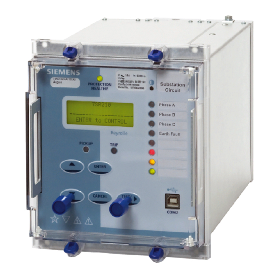
Dielectric Test Voltage 2kV Impulse Test Above 5kV Caution: Refer to Equipment Documentation Caution: Risk of Electric Shock Figure 2.5 7SR21 with 3 + 8 LEDs in E6 Case ©2010 Siemens Protection Devices Limited Chapter 1 Page 15 of 71... -
Page 16: Figure 2.5-2 7Sr22 With 3 + 16 Leds In E8 Case
7SR21 & 7SR22 Argus Description of Operation Figure 2.5-1 7SR22 with 3 + 16 LEDs in E8 Case Figure 2.5-2 7SR22 with Function Keys and 3 + 8 LEDs in E8 Case NOTE: Pushbuttons on cover not shown The fascia is an integral part of the relay. Handles are located at each side of the element to allow it to be withdrawn from the relay case. - Page 17 7SR21 & 7SR22 Argus Description of Operation Relay Information Above the LCD three labels are provided, these provide the following information: 1) Product name and order code. 2) Nominal current rating, rated frequency, voltage rating, auxiliary dc supply rating, binary input supply rating, configuration and serial number.
-
Page 18: Current Inputs
Function keys can be used with Quick Logic. Current Inputs Four current inputs are provided in the 7SR21 relay and five inputs are provided in the 7SR22 relay Current inputs are located on the Analogue Input module. Terminals are available for both 1A and 5A inputs. -
Page 19: Binary Inputs
The Power Supply module includes the relay basic I/O. The module includes 3 x BI and 6 x BO. Non-directional (7SR21) relays have an additional 6 x BI on the analogue module. Additional I/O modules may be fitted, these provide 10 x BI. -
Page 20: Binary Outputs (Output Relays)
– providing in total 1 x normally closed (NC), 2 x change-over (CO) and 3 x normally open (NO) contacts. Non-directional (7SR21) relays have two additional binary outputs providing 2 x NO contacts on the analogue module. Additional I/O modules may be fitted; these provide 8 x NO contacts. -
Page 21: 2.10 Virtual Input/Outputs
7SR21 & 7SR22 Argus Description of Operation 2.10 Virtual Input/Outputs The relays have 16 virtual input/outputs, these are internal logic states. Virtual I/O is assigned in the same way as physical Binary Inputs and Binary Outputs. Virtual I/O is mapped from within the INPUT CONFIG > INPUT MATRIX and OUTPUT CONFIG >... -
Page 22: Section 3: Protection Functions
7SR21 & 7SR22 Argus Description of Operation Section 3: Protection Functions Current Protection: Phase Overcurrent (67, 51, 50) All phase overcurrent elements have a common setting to measure either fundamental frequency RMS or True RMS current: True RMS current: 51/50 Measurement = RMS Fundamental Frequency RMS current: 51/50 Measurement = Fundamental 3.1.1... -
Page 23: Figure 3.1-1 Logic Diagram: Directional Overcurrent Element (67)
7SR21 & 7SR22 Argus Description of Operation Minimum Polarising Voltage The 67 Minimum Voltage setting defines the minimum polarising voltage level. Where the measured polarising voltage is below this level no directional output is given and operation of protection elements set as directional will be inhibited. -
Page 24: Instantaneous Overcurrent Protection (50)
3.1.2 Instantaneous Overcurrent Protection (50) Two instantaneous overcurrent elements are provided in the 7SR21 relay. Four elements are provided in the 7SR22 e.g. giving the option of using two elements set to forward and two to reverse. Each instantaneous element (50-n) has independent settings. 50-n Setting for pick-up current and 50-n Delay follower time delay. -
Page 25: Time Delayed Overcurrent Protection (51)
3.1.3 Time Delayed Overcurrent Protection (51) Two time delayed overcurrent elements are provided in the 7SR21 relay. Four elements are provided in the 7SR22 relay e.g. giving the option of using two elements set to forward and two to reverse. -
Page 26: Figure 3.1-3 Logic Diagram: Time Delayed Overcurrent Element
7SR21 & 7SR22 Argus Description of Operation See Voltage Controlled Overcurrent (51V) 51-n Element 51-n Setting Enabled 51-n Charact AUTORECLOSE Disabled & 51-n Time Mult 79 P/F Inst Trips = 51-n & 51-n Delay (DTL) 79 P/F Prot’n Trip n = Delayed 51-n Min. -
Page 27: Current Protection: Voltage Controlled Overcurrent (51V) - 7Sr22
7SR21 & 7SR22 Argus Description of Operation Current Protection: Voltage Controlled Overcurrent (51V) – 7SR22 Voltage controlled overcurrent is available in the 7SR22 relay. Each shaped overcurrent element 51-n Setting can be independently controlled by the level of measured (control) input voltage. -
Page 28: Current Protection: Derived Earth Fault (67N, 51N, 50N)
7SR21 & 7SR22 Argus Description of Operation Current Protection: Derived Earth Fault (67N, 51N, 50N) The earth current is derived by calculating the sum of the measured line currents. The elements measure the fundamental frequency RMS current. 3.3.1 Directional Control of Derived Earth Fault Protection (67N) – 7SR22 The directional element produces forward and reverse outputs for use with derived earth fault elements. -
Page 29: Instantaneous Derived Earth Fault Protection (50N)
Instantaneous Derived Earth Fault Protection (50N) Two instantaneous derived earth fault elements are provided in the 7SR21 relay. Four elements are provided in the 7SR22 relay e.g. giving the option of using two elements set to forward and two to reverse. -
Page 30: Time Delayed Derived Earth Fault Protection (51N)
Time Delayed Derived Earth Fault Protection (51N) Two time delayed derived earth fault elements are provided in the 7SR21 relay. Four elements are provided in the 7SR22 relay e.g. giving the option of using two elements set to forward and two to reverse. -
Page 31: Figure 3.3-3 Logic Diagram: Derived Time Delayed Earth Fault Protection
7SR21 & 7SR22 Argus Description of Operation Figure 3.3-3 Logic Diagram: Derived Time Delayed Earth Fault Protection ©2010 Siemens Protection Devices Limited Chapter 1 Page 31 of 71... -
Page 32: Current Protection: Measured Earth Fault (67G, 51G, 50G)
7SR21 & 7SR22 Argus Description of Operation Current Protection: Measured Earth Fault (67G, 51G, 50G) The earth current is measured directly via a dedicated current analogue input. All measured earth fault elements have a common setting to measure either fundamental frequency RMS or True... -
Page 33: Instantaneous Measured Earth Fault Protection (50G)
Instantaneous Measured Earth Fault Protection (50G) Two instantaneous measured earth fault elements are provided in the 7SR21 relay. Four elements are provided in the 7SR22 relay e.g. giving the option of using two elements set to forward and two to reverse. -
Page 34: Time Delayed Measured Earth Fault Protection (51G)
Time Delayed Measured Earth Fault Protection (51G) Two time delayed measured earth fault elements are provided in the 7SR21 relay. Four elements are provided in the 7SR22 relay e.g. giving the option of using two elements set to forward and two to reverse. -
Page 35: Current Protection: Sensitive Earth Fault (67Sef, 51Sef, 50Sef)
7SR21 & 7SR22 Argus Description of Operation Current Protection: Sensitive Earth Fault (67SEF, 51SEF, 50SEF) Current for the Sensitive Earth Fault (SEF) elements is measured directly via a dedicated current analogue input. SEF elements measure the fundamental frequency RMS current. -
Page 36: Instantaneous Sensitive Earth Fault Protection (50Sef)
3.5.2 Instantaneous Sensitive Earth Fault Protection (50SEF) Two instantaneous SEF elements are provided in the 7SR21 relay. Four elements are provided in the 7SR22 relay e.g. giving the option of using two elements set to forward and two to reverse. -
Page 37: Figure 3.5-3 Logic Diagram: Sef Time Delayed Element (51Sef)
3.5.3 Time Delayed Sensitive Earth Fault Protection (51SEF) Two time delayed sensitive earth fault elements are provided in the 7SR21 relay. Four elements are provided in the 7SR22 relay. e.g. giving the option of using two elements set to forward and two to reverse. -
Page 38: Current Protection: High Impedance Restricted Earth Fault (64H)
7SR21 & 7SR22 Argus Description of Operation Current Protection: High Impedance Restricted Earth Fault (64H) One high impedance Restricted Earth Fault (REF) element is provided. The relay utilises fundamental current measurement values for this function. The single phase current input is derived from the residual output of line/neutral CTs connected in parallel. An external stabilising resistor must be connected in series with this input to ensure that this element provides a high impedance path. -
Page 39: Current Protection: Cold Load (51C)
7SR21 & 7SR22 Argus Description of Operation Current Protection: Cold Load (51c) The setting of each shaped overcurrent element (51-n) can be inhibited and alternative ‘cold load’ settings (51c-n) can be applied for a period following circuit switch in. The Cold Load settings are applied after the circuit breaker has been open for longer than the Pick-Up Time setting. -
Page 40: Current Protection: Negative Phase Sequence Overcurrent (46Nps)
7SR21 & 7SR22 Argus Description of Operation Current Protection: Negative Phase Sequence Overcurrent (46NPS) The negative sequence phase (NPS) component of current (I2) is derived from the three phase currents. It is a measure of the quantity of unbalanced current in the system. -
Page 41: Current Protection: Under-Current (37, 37G & 37Sef)
7SR21 & 7SR22 Argus Description of Operation Current Protection: Under-Current (37, 37G & 37SEF) Two under-current elements are provided for each 37, 37G & 37SEF protection function. Each phase has an independent level detector and current-timing element. 37-n Setting sets the pick-up current. -
Page 42: Current Protection: Thermal Overload (49)
7SR21 & 7SR22 Argus Description of Operation 3.10 Current Protection: Thermal Overload (49) The relay provides a thermal overload suitable for the protection of static plant. Phase segregated elements are provided. The temperature of the protected equipment is not measured directly. Instead, thermal overload conditions are calculated using the measure True RMS current. -
Page 43: Figure 3.10-1 Logic Diagram: Thermal Overload Protection (49S)
7SR21 & 7SR22 Argus Description of Operation 49 Overload Setting 49 Therm. Overload 49 Time Constant Enabled 49 Capacity Alarm Disabled & Inhibit 49 cap alarm trip 49 Alarm cap alarm trip 49 Trip cap alarm trip Figure 3.10-1 Logic Diagram: Thermal Overload Protection (49S) ©2010 Siemens Protection Devices Limited... -
Page 44: Voltage Protection: Phase Under/Over Voltage (27/59) - 7Sr22
7SR21 & 7SR22 Argus Description of Operation 3.11 Voltage Protection: Phase Under/Over Voltage (27/59) - 7SR22 In total five under/over voltage elements are provided in the 7SR22 relay. Four elements are provided for the ‘Phase’ Voltages and one for the ‘Auxiliary’ input voltage. -
Page 45: Voltage Protection: Negative Phase Sequence Overvoltage (47) - 7Sr22
7SR21 & 7SR22 Argus Description of Operation 3.12 Voltage Protection: Negative Phase Sequence Overvoltage (47) – 7SR22 Negative phase sequence (NPS) voltage (V2) is a measure of the quantity of unbalanced voltage in the system. The relay derives the NPS voltage from the three input voltages (VL1, VL2 and VL3). -
Page 46: 3.13 Voltage Protection: Neutral Overvoltage (59N) - 7Sr22
7SR21 & 7SR22 Argus Description of Operation 3.13 Voltage Protection: Neutral Overvoltage (59N) – 7SR22 Two Neutral Overvoltage (or Neutral Voltage Displacement) elements are provided in the 7SR22 relay. 59N Voltage Source setting selects the source of the residual voltage to be measured. The voltage is measured directly from the Vx input or derived from the line voltages where suitable VT connections are present. -
Page 47: 3.14 Voltage Protection: Under/Over Frequency (81) - 7Sr22
7SR21 & 7SR22 Argus Description of Operation 3.14 Voltage Protection: Under/Over Frequency (81) – 7SR22 Six under/over frequency elements are provided in the 7SR22 relay. The relay utilises fundamental voltage measurement values for this function. The frequency calculation is based on the highest input voltage derived from the voltage selection algorithm. -
Page 48: Section 4: Control & Logic Functions
7SR21 & 7SR22 Argus Description of Operation Section 4: Control & Logic Functions Auto-Reclose (79) 4.1.1 Overview A high proportion of faults on an Overhead Line (OHL) network are transient. These faults can be cleared and the network restored quickly by using Instantaneous (Fast) Protection trips followed by an automated sequence of Circuit Breaker (CB) reclosures after the line has been dead for a short time, this ‘deadtime’... - Page 49 7SR21 & 7SR22 Argus Description of Operation Indications The Instruments Menu includes the following meters relevant to the status of the Auto-Reclose and Manual Closing of the circuit breaker: - Autoreclose Status Out of Service Close Shot. CB Open Countdown Timer...
-
Page 50: 4.1.2 Auto Reclose Sequences
7SR21 & 7SR22 Argus Description of Operation 4.1.2 Auto Reclose sequences The CONTROL & LOGIC>AUTO RECLOSE PROT’N and CONTROL & LOGIC>AUTORECLOSE CONFIG’ menus, allow the user to set independent Protection and Auto Reclose sequences for each type of fault i.e. Phase Fault (P/F), Derived/Measured Earth Fault (E/F), Sensitive Earth Fault (SEF) or External Protections (EXTERN). -
Page 51: Autoreclose Prot'n Menu
7SR21 & 7SR22 Argus Description of Operation Autoreclose Prot’n Menu This menu presents the Overcurrent Protection elements available for each type of Fault i.e. P/F, E/F or SEF and allows the user to select those that are to be applied as Inst trips; those that are to be applied as Delayed Trips;... - Page 52 7SR21 & 7SR22 Argus Description of Operation • At the end of the 79 Reclose Blocked Delay due to presence of a persistent Block signal. • When the 79 Elem HS Trips to Lockout count is reached. • When the 79 Elem Delayed Trips to Lockout count is reached.
-
Page 53: P/F Shots Sub-Menu
7SR21 & 7SR22 Argus Description of Operation P/F Shots Sub-Menu This menu allows the Phase fault trip/reclose sequence to be parameterized:- The first protection Trip in the P/F sequence can be set to either Inst or Delayed. 79 P/F Prot’n Trip1 Sets the first Reclose Delay (Dead time) in the P/F sequence. -
Page 54: Extern Shots Sub-Menu
7SR21 & 7SR22 Argus Description of Operation Extern Shots Sub-Menu This menu allows the External Protection auto-reclose sequence to be parameterized:- Not Blocked/Blocked - Blocked raises an output which can be mapped to a Binary 79 P/F Prot’n Trip1 output to Block an External Protection’s Trip Output. -
Page 55: Figure 4.7-1 Basic Auto-Reclose Sequence Diagram
7SR21 & 7SR22 Argus Description of Operation Figure 4.7-1 Basic Auto-Reclose Sequence Diagram ©2010 Siemens Protection Devices Limited Chapter 1 Page 55 of 71... -
Page 56: Manual Control
7SR21 & 7SR22 Argus Description of Operation Manual Control A Manual Close Command can be initiated in one of three ways: via a Close CB binary input, via the data communication Channel(s) or from the relay CONTROL MODE menu. It causes an instantaneous operation via 79MC Close CB binary output, over-riding any AR sequence in progress. -
Page 57: Figure 4.9-1 Logic Diagram: Circuit Breaker Status
7SR21 & 7SR22 Argus Description of Operation Blocked Close Delay The close command may be delayed by a Block Close CB signal applied to a binary input. This causes the feature to pause before it issues the CB close command and can be used, for example, to delay CB closure until the CB energy has reached an acceptable level. -
Page 58: 4.10 Quick Logic
7SR21 & 7SR22 Argus Description of Operation 4.10 Quick Logic The ‘Quick Logic’ feature allows the user to input up to 16 logic equations (E1 to E16) in text format. Equations can be entered using Reydisp or at the relay fascia. -
Page 59: Figure 4.10-1 Sequence Diagram: Quick Logic Pu/Do Timers (Counter Reset Mode Off)
7SR21 & 7SR22 Argus Description of Operation Figure 4.10-1 Sequence Diagram: Quick Logic PU/DO Timers (Counter Reset Mode Off) When the count value = En Counter Target the output of the counter (En) = 1 and this value is held until the initiating conditions are removed when En is instantaneously reset. -
Page 60: Section 5: Supervision Functions
7SR21 & 7SR22 Argus Description of Operation Section 5: Supervision Functions Circuit Breaker Failure (50BF) The circuit breaker fail function has two time delayed outputs that can be used for combinations of re-tripping or back-tripping. CB Fail outputs are given after elapse of the 50BF-1 Delay or 50BF-2 Delay settings. The two timers run concurrently. -
Page 61: Vt Supervision (60Vts) - 7Sr22
7SR21 & 7SR22 Argus Description of Operation VT Supervision (60VTS) – 7SR22 1 or 2 Phase Failure Detection Normally the presence of negative phase sequence (NPS) or zero phase sequence (ZPS) voltage in a power system is accompanied by NPS or ZPS current. The presence of either of these sequence voltages without the equivalent level of the appropriate sequence current is used to indicate a failure of one or two VT phases. -
Page 62: Figure 5.2-1 Logic Diagram: Vt Supervision Function (60Vts)
7SR21 & 7SR22 Argus Description of Operation 60VTS Element Enabled Disabled & 60VTS Inhibit 1 or 2 Phase Fail 60VTS V Setting Component > Phase Seq. Filter & NPS/ZPS 60VTS Delay I Setting Phase Seq. & < Filter > 1... -
Page 63: Ct Supervision (60Cts & 60Cts-I)
Operation of the CT supervision elements can be inhibited from: A binary or virtual input. Inhibit 60CTS-I Figure 5.4-1 Logic Diagram: CT Supervision Function (60CTS-I) – 7SR21 & 7SR22 (60CTS) – 7SR22 Normally the presence of negative phase sequence (NPS) current in a power system is accompanied by NPS voltage. -
Page 64: Broken Conductor (46Bc)
7SR21 & 7SR22 Argus Description of Operation Broken Conductor (46BC) The element calculates the ratio of NPS to PPS currents. Where the NPS:PPS current ratio is above 46BC Setting an output is given after the 46BC Delay. The Broken Conductor function can be inhibited from A binary or virtual input or function key. -
Page 65: Inrush Restraint (81Hbl2)
7SR21 & 7SR22 Argus Description of Operation Inrush Restraint (81HBL2) Inrush restraint detector elements are provided, these monitor the line currents. The inrush restraint detector can be used to block the operation of selected elements during transformer magnetising inrush conditions. -
Page 66: Section 6: Other Features
7SR21 & 7SR22 Argus Description of Operation Section 6: Other Features Data Communications Two communication ports, COM1 and COM2 are provided. RS485 connections are available on the terminal blocks at the rear of the relay (COM1). A USB port, COM 2, is provided at the front of the relay for local access using a PC. -
Page 67: Data Storage
7SR21 & 7SR22 Argus Description of Operation Data Storage 6.3.1 General The relay stores three types of data records: relay event records, analogue/digital waveform records and fault records. Data records are backed up in non-volatile memory and are permanently stored even in the event of loss of auxiliary d.c. -
Page 68: Waveform Records
7SR21 & 7SR22 Argus Description of Operation 6.3.4 Waveform Records. Relay waveform storage can be triggered either after user selected relay operations, from the relay fascia, from a suitably programmed binary input or via the data comms channel(s). The stored analogue and digital waveforms illustrate the system and relay conditions at the time of trigger. -
Page 69: Operating Mode
7SR21 & 7SR22 Argus Description of Operation Operating Mode The relay has three operating modes, Local, Remote and Out of Service. The following table identifies the functions operation in each mode. The modes can be selected by the following methods: SYSTEM CONFIG>RELAY MODE setting, a Binary Input or Command... -
Page 70: Real Time Clock
7SR21 & 7SR22 Argus Description of Operation Real Time Clock Time and date can be set either via the relay fascia using appropriate commands in the System Config menu, via the data comms channel(s) or via the optional IRIG-B input. Time and date are maintained while the relay is de- energised by a back up storage capacitor. -
Page 71: 2010 Siemens Protection Devices Limited Chapter
The password validation screen also displays a numerical code. If the password is lost or forgotten, this code should be communicated to Siemens Protection Devices Ltd. and the password can be retrieved. ©2010 Siemens Protection Devices Limited Chapter 1 Page 71 of 71...