HP MSA 2040 User Manual
Hide thumbs
Also See for MSA 2040:
- Quickspecs (35 pages) ,
- Troubleshooting manual (30 pages) ,
- Firmware release notes (9 pages)
Table of Contents
Quick Links
See also:
Troubleshooting Manual
HP MSA 2040
User Guide
For firmware release GL200 or later
Abstract
This document describes initial hardware setup for HP MSA 2040 controller enclosures, and is intended for use by storage system
administrators familiar with servers and computer networks, network administration, storage system installation and configuration,
storage area network management, and relevant protocols.
HP Part Number: 723983-003
Published: September 2014
Edition: 1
Table of Contents
Troubleshooting

Related Manuals for HP MSA 2040


Summary of Contents for HP MSA 2040
-
Page 1: User Guide
For firmware release GL200 or later Abstract This document describes initial hardware setup for HP MSA 2040 controller enclosures, and is intended for use by storage system administrators familiar with servers and computer networks, network administration, storage system installation and configuration, storage area network management, and relevant protocols. - Page 2 The information contained herein is subject to change without notice. The only warranties for HP products and services are set forth in the express warranty statements accompanying such products and services. Nothing herein should be construed as constituting an additional warranty. HP shall not be liable for technical or editorial errors or omissions contained herein.
-
Page 3: Table Of Contents
MSA 2040 Array SFF enclosure ..........13 MSA 2040 Array LFF or supported drive expansion enclosure ......13 Disk drives used in MSA 2040 enclosures . - Page 4 Connecting switch attach configurations ..........37 Dual controller configuration .
- Page 5 MSA 2040 6 Gb 3.5" 12-drive enclosure—rear panel layout ......87...
- Page 6 C Specifications and requirements ........89 Safety requirements .
- Page 7 6 MSA 2040 SAS controller module face plate (HD mini-SAS) ......
- Page 8 Figures...
- Page 9 Tables 1 Installation checklist ............19 2 Terminal emulator display settings .
- Page 10 Tables...
-
Page 11: Overview
The MSA 2040 enclosures support either large form factor (LFF 12-disk) or small form factor (SFF 24-disk) 2U chassis, using either AC or DC power supplies. HP MSA Storage models include MSA 2040 SAN and MSA 2040 SAS controllers, which are introduced below. -
Page 12: Msa 2040 Sas
"MSA 2040 SAN controller module—rear panel LEDs" (page 83) for more information. IMPORTANT: See the “HP MSA 2040 SAN Storage array and iSCSI SFPs Read This First” document for important information pertaining to iSCSI SFPs. TIP: See the “Configuring host ports” topic within the SMU Reference Guide for information about configuring Converged Network Controller ports with host interface protocols of the same type or a combination of types. -
Page 13: Components
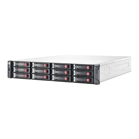
Components Front panel components HP MSA 2040 models support small form factor (SFF) and large form factor (LFF) enclosures. The SFF chassis, configured with 24 2.5" SFF disks, is used as a controller enclosure. The LFF chassis, configured with 12 3.5" LFF disks, is used as either a controller enclosure or a drive enclosure. -
Page 14: Disk Drives Used In Msa 2040 Enclosures
LFF/SFF Midline SAS and LFF/SFF Enterprise self-encrypting disks that work with the Full Disk Encryption (FDE) features. For information about creating disk groups and adding spares using these different disk drive types, see the HP MSA 2040 SMU Reference Guide and HP MSA 2040 Solid State Drive Read This First document. Also see"FDE considerations"... -
Page 15: Msa 2040 San Controller Module-Rear Panel Components
Service port 2 (used by service personnel only) (Sticker shown covering the opening) Reserved for future use SAS expansion port Figure 4 MSA 2040 SAN controller module face plate (FC or 10GbE iSCSI) Figure 5 shows Converged Network Controller ports configured with 1 Gb RJ-45 SFPs. 6Gb/s... -
Page 16: Msa 2040 Sas Controller Module-Rear Panel Components
USB Type - B CLI port for accessing the Command-line Interface via a telnet client. Drive enclosures Drive enclosure expansion modules attach to MSA 2040 controller modules via the mini-SAS expansion port, allowing addition of disk drives to the system. MSA 2040 controller enclosures support adding the 6 Gb drive enclosures described below. Components... -
Page 17: Lff Drive Enclosure - Rear Panel Layout
Figure 7 LFF 12-drive enclosure: rear panel SFF drive enclosure MSA 2040 controllers support the D2700 6 Gb drive enclosure for adding storage. For information about this product, visit http://www.hp.com/support. Pictorial representations of this drive enclosure are also provided in the MSA 2040 Quick Start Instructions and MSA 2040 Cable Configuration Guide. -
Page 18: Supercapacitor Pack
(subject to volume write optimization setting). Supercapacitor pack To protect RAID controller cache in case of power failure, MSA 2040 controllers are equipped with supercapacitor technology, in conjunction with CompactFlash memory, built into each controller module to provide extended cache memory backup time. The supercapacitor pack provides energy for backing up unwritten data in the write cache to the CompactFlash in the event of a power failure. -
Page 19: Installing The Enclosures
Follow the “Removing the failed drive” and “Installing the replacement drive” procedures within the HP MSA Drive Module Replacement Instructions. Import the keys for the disks so that the disk content becomes available. -
Page 20: Connecting Controller And Drive Enclosures
Connecting the MSA 2040 controller to the LFF drive enclosure The LFF MSA 2040 6 Gb 3.5"12-drive enclosure, supporting 6 Gb internal disk drive and expander link speeds, can be attached to an MSA 2040 controller enclosure using supported mini-SAS to mini-SAS cables of 0.5 m (1.64') to 2 m (6.56') length [see... -
Page 21: Connecting The Msa 2040 Controller To Mixed Model Drive Enclosures
Connecting the MSA 2040 controller to mixed model drive enclosures MSA 2040 controllers support cabling of 6 Gb SAS link-rate LFF and SFF expansion modules—in mixed model fashion—as shown in Figure 13 (page 25), and further described in the HP MSA 2040 Cable Configuration Guide;... -
Page 22: Cabling Connections Between The Msa 2040 Controller And A Single Drive Enclosure
= SFF 25-drive enclosure = LFF 12-drive enclosure Figure 9 Cabling connections between the MSA 2040 controller and a single drive enclosure The figure above shows examples of the MSA 2040 controller enclosure—equipped with a single controller module—cabled to a single drive enclosure equipped with a single expansion module. The empty I/O module slot in each of the enclosures is covered with an IOM blank to ensure sufficient air flow during enclosure operation. -
Page 23: Cabling Connections Between Msa 2040 Controllers And Lff Drive Enclosures
Figure 1 1 Cabling connections between MSA 2040 controllers and LFF drive enclosures The diagram at left (above) shows fault-tolerant cabling of a dual-controller enclosure cabled to MSA 2040 6 Gb 3.5" 12-drive enclosures featuring dual-expansion modules. Controller module 1A is connected to expansion module 2A, with a chain of connections cascading down (blue). -
Page 24: Cabling Connections Between Msa 2040 Controllers And Sff Drive Enclosures
Straight-through cabling Figure 12 Cabling connections between MSA 2040 controllers and SFF drive enclosures The figure above provides sample diagrams reflecting cabling of MSA 2040 controller enclosures and D2700 6 Gb drive enclosures. The diagram at left shows fault-tolerant cabling of a dual-controller enclosure and D2700 6 Gb drive enclosures featuring dual-expansion modules. -
Page 25: Cabling Connections Between Msa 2040 Controllers And Drive Enclosures Of Mixed Model Type
= LFF 12-drive enclosure = SFF 25-drive enclosure Figure 13 Cabling connections between MSA 2040 controllers and drive enclosures of mixed model type The figure above provides sample diagrams reflecting cabling of MSA 2040 controller enclosures and supported mixed model drive enclosures. In this example, the SFF drive enclosures follow the LFF drive enclosures. -
Page 26: Fault-Tolerant Cabling Connections Showing Maximum Number Of Enclosures Of Same Type
The figure above provides sample diagrams reflecting fault-tolerant cabling of a maximum number of supported MSA 2040 enclosures. The diagram at left shows fault-tolerant cabling of an MSA 2040 controller enclosure and seven LFF drive enclosures; whereas the diagram at right shows fault-tolerant cabling of an MSA 2040 controller enclosure and seven D2700 drive enclosures. -
Page 27: Cabling Connections Showing Maximum Enclosures Of Mixed Model Type
SFF drive enclosures. Given that both drive enclosure models use 6 Gb SAS link-rate and SAS2.0 expanders, they can be ordered in desired sequence within the array, following the controller enclosure. MSA 2040 controller enclosures support up to eight enclosures (including the controller enclosure) for adding storage. -
Page 28: Testing Enclosure Connections
Connect the cables and power cords to the enclosures as explained in the quick start instructions. NOTE: MSA 2040 controller enclosures and drive enclosures do not have power switches (they are switchless). They power on when connected to a power source, and they power off when disconnected. -
Page 29: Dc And Ac Power Supplies Equipped With A Power Switch
Proceed to step • Use the CLI to shut down both controllers, as described in the HP MSA 2040 CLI Reference Guide. Disconnect the power cord male plug from the power source. Disconnect the power cord female plug from the power cord connector on the power supply. -
Page 30: Connect Power Cable To Dc Power Supply
Connect power cable to DC power supply Locate two DC power cables that are compatible with your controller enclosure. Connector pins (typical 2 places) Ring/lug connector (typical 3 places) Connector (front view) Figure 18 DC power cable featuring sectioned D-shell and lug connectors Figure 18 and the illustration at left (in Figure... - Page 31 • Use the SMU to shut down both controllers, as described in the online help and HP MSA 2040 SMU Reference Guide. Proceed to step • Use the CLI to shut down both controllers, as described in the HP MSA 2040 CLI Reference Guide.
- Page 32 Installing the enclosures...
-
Page 33: Connecting Hosts
Use the set host-port-mode CLI command to set the host interface protocol for MSA 2040 SAN host ports using qualified SFP options. MSA 2040 SAN models ship with host ports configured for FC. When connecting host ports to iSCSI hosts, you must use the CLI (not the SMU) to specify which ports will use iSCSI. -
Page 34: Fibre Channel Protocol
Each controller module provides four host ports designed for use with an FC SFP supporting data rates up to 16 Gbit/s. When configured with FC SFPs, MSA 2040 SAN controller enclosures can also be cabled to support the optionally-licensed Remote Snap replication feature via the FC ports. -
Page 35: Gb Iscsi Protocol
Remote Snap replication feature. To connect the MSA 2040 SAN controller to a server or switch—using the 1 Gb SFPs in controller ports—select the appropriate qualified RJ-45 SFP option (see the QuickSpecs). Such cables are also used for connecting a local storage system to a remote storage system via a switch, to facilitate use of the optional Remote Snap replication feature. -
Page 36: Single-Controller Configurations
Single-controller configurations One server/one HBA/single path MSA 2040 SAN Server 6Gb/s IOM blank MSA 2040 SAS Server 12Gb/s 12Gb/s 6Gb/s IOM blank Figure 19 Connecting hosts: direct attach—one server/one HBA/single path Dual-controller configurations One server/one HBA/dual path MSA 2040 SAN... -
Page 37: Four Servers/One Hba Per Server/Dual Path
Four servers/one HBA per server/dual path MSA 2040 SAN Server 1 Server 2 Server 3 Server 4 6Gb/s 6Gb/s MSA 2040 SAS Server 1 Server 2 Server 3 Server 4 12Gb/s 12Gb/s 6Gb/s 12Gb/s 12Gb/s 6Gb/s Figure 22 Connecting hosts: direct attach—four servers/one HBA per server/dual path... -
Page 38: Four Servers/Multiple Switches/San Fabric
Replication configuration possibilities are many, and can be cabled—in switch attach fashion—to support MSA 2040 SAN systems on the same network, or on different networks (MSA 2040 SAS systems do not support replication). As you consider the physical connections of your system—specifically connections for replication—keep several important points in mind:... -
Page 39: Cabling For Replication
Once the MSA 2040 systems are physically cabled, see the SMU Reference Guide or online help for information about configuring, provisioning, and using the optional Remote Snap feature. -
Page 40: Host Ports And Replication
Host ports and replication MSA 2040 SAN controller modules can use qualified SFP options of the same type, or they can use a combination of qualified SFP options supporting different interface protocols. If you use a combination of different protocols, then host ports 1 and 2 are set to FC (either both16 Gbit/s or both 8 Gbit/s), and host ports 3 and 4 must be set to iSCSI (either both 10GbE or both 1 Gb). -
Page 41: Multiple Servers/Different Networks/Multiple Switches
Since each switch would include both VLANs or zones, the configuration would function as multiple networks. Multiple servers/different networks/multiple switches The diagram below shows the rear panel of two MSA 2040 SAN controller enclosures with both I/O and replication occurring on different networks. Peer sites with failover... -
Page 42: Connecting Two Storage Systems For Remote Snap: Multiple Servers/San Fabric/Two Locations
= "B" Application servers Figure 29 Connecting two storage systems for Remote Snap: multiple servers/SAN fabric/two locations Although not shown in the preceding cabling examples, you can cable replication-enabled MSA 2040 SAN systems and compatible P2000 G3 systems—via switch attach—for performing replication tasks. -
Page 43: Updating Firmware
Firmware. The Update Firmware panel displays the currently installed firmware versions, and enables you to update them. Optionally, you can update firmware using FTP (File Transfer Protocol) as described in the MSA 2040 SMU Reference Guide. IMPORTANT: See the “About firmware update” and “Updating firmware” topics within the MSA 2040 SMU Reference Guide before performing a firmware update. - Page 44 Connecting hosts...
-
Page 45: Connecting To The Controller Cli Port
Obtaining IP values One method of obtaining IP values for your system is to use a network management utility to discover “HP MSA Storage” devices on the local LAN through SNMP. Alternative methods for obtaining IP values for your system are described in the following subsections. -
Page 46: Setting Network Port Ip Addresses Using The Cli Port And Cable
NOTE: For more information, see “Using the Configuration Wizard” and scroll to the network ports topic within the HP MSA 2040 SMU Reference Guide. Setting network port IP addresses using the CLI port and cable You can set network port IP addresses manually using the command-line interface port and cable. If you have not done so already, you need to enable your system for using the command-line interface port [also "Using the CLI port and cable—known issues on Windows"... -
Page 47: Terminal Emulator Display Settings
Enable the CLI port for subsequent communication: • Linux customers should enter the command syntax provided in "Preparing a Linux computer before cabling to the CLI port" (page 45). • Windows customers should locate the downloaded device driver described in "Downloading a device driver for Windows computers"... - Page 48 2 page 46. The USB device driver is also available from the Software Support and Documentation CD that shipped with your product. NOTE: Access the download from your HP MSA support website at http://www.hp.com/support. Connecting to the controller CLI port...
-
Page 49: Using The Cli Port And Cable-Known Issues On Windows
Using the CLI port and cable—known issues on Windows When using the CLI port and cable for setting controller IP addresses, be aware of the following known issues on Microsoft Windows platforms. Problem On Windows operating systems, the USB CLI port may encounter issues preventing the terminal emulator from reconnecting to storage after the Management Controller (MC) restarts or the USB cable is unplugged and reconnected. - Page 50 Connecting to the controller CLI port...
-
Page 51: Basic Operation
IMPORTANT: For detailed information on accessing and using the SMU, see the “Getting started” section in the web-posted HP MSA 2040 SMU Reference Guide. The Getting Started section provides instructions for signing-in to the SMU, introduces key concepts, addresses browser setup, and provides tips for using the main window and the help window. - Page 52 Basic operation...
-
Page 53: Troubleshooting
Troubleshooting USB CLI port connection MSA 2040 controllers feature a CLI port employing a mini-USB Type B form factor. If you encounter problems communicating with the port after cabling your computer to the USB device, you may need to either download a device driver (Windows), or set appropriate parameters via an operating system command (Linux). -
Page 54: Use The Cli
Use the CLI As an alternative to using the SMU, you can run the show system command in the CLI to view the health of the system and its components. If any component has a problem, the system health will be Degraded, Fault, or Unknown, and those components will be listed as Unhealthy Components. -
Page 55: Isolate The Fault
Informational. A configuration or state change occurred, or a problem occurred that the system corrected. No immediate action is required. See the HP MSA Event Descriptions Reference Guide for information about specific events, located at your HP MSA 2040 manuals page: http://www.hp.com/support/msa2040/manuals. -
Page 56: Diagnostic Steps
3 is zero. See the HP MSA 2040 CLI Reference Guide for additional information, at your HP MSA 2040 manuals page: http://www.hp.com/support/msa2040/manuals. Diagnostic steps This section describes possible reasons and actions to take when an LED indicates a fault condition during initial system setup. -
Page 57: Is The Enclosure Rear Panel Fru Ok Led Off
• The disk is not configured. Table 7 Diagnostics LED status: Front panel disks “Online/Activity” and “Fault/UID” NOTE: "Disk drives used in MSA 2040 enclosures" (page 14). Is the disk drive module Fault/UID LED blinking amber? Answer Possible reasons Actions No, but the The disk drive is rebuilding. -
Page 58: Is A Connected Host Port Host Link Status Led Off
Answer Possible reasons Actions Yes, and the The disk drive is offline. A • Check the event log for specific information regarding the Online/Activity predictive failure alert may have fault. LED is off. been received for this device. • Isolate the fault. •... -
Page 59: Is A Connected Port Network Port Link Status Led Off
Is a connected port Network Port Link Status LED off? Answer Possible reasons Actions System functioning properly. No action required. The link is down. Use standard networking troubleshooting procedures to isolate faults on the network. Table 1 1 Diagnostics LED status: Rear panel “Network Port Link Status” Is the power supply Input Power Source LED off? Answer Possible reasons... -
Page 60: If The Controller Has Failed Or Does Not Start, Is The Cache Status Led On/Blinking
To preserve the existing data stored in the CompactFlash, you must transport the CompactFlash from the failed controller to a replacement controller using the procedure outlined in HP MSA Controller Module Replacement Instructions shipped with the replacement controller module. Failure to use this procedure will result in the loss of data stored in the cache module. -
Page 61: Host-Side Connection Troubleshooting Featuring Sas Host Ports
SFPs, cables, and HBAs. Host-side connection troubleshooting featuring SAS host ports The procedure below applies to MSA 2040 SAS controller enclosures employing 12 Gb SFF-8644 connectors in the HD mini-SAS host ports used for I/O. Halt all I/O to the storage system as described in "Stopping I/O"... -
Page 62: Isolating A Controller Module Expansion Port Connection Fault
• Flashing at 1/10 second on and 9/10 second off – Cache is being refreshed by the supercapacitor. • Off – Cache is clean (no unwritten data). Reseat the host cable and inspect for damage. Is the host link status LED on? •... -
Page 63: Isolating Remote Snap Replication Faults
• See HP Remote Snap technical white paper for replication best practices • See HP MSA 2040 SMU Reference Guide for procedures to setup and manage replications • See HP MSA 2040 CLI Reference Guide for replication commands and syntax See HP MSA Event Descriptions Reference Guide for replication event reporting •... -
Page 64: Diagnostic Steps For Replication Setup
If the Replication feature is not enabled, obtain and install a valid license for Remote Snap. NOTE: Remote Snap is not supported by MSA 2040 SAS controller enclosures. Compatible firmware revision Perform the following actions on each system used for replication: supporting Remote Snap is not •... -
Page 65: Can You Create A Replication Set
Can you create a replication set? Answer Possible reasons Actions System functioning properly. No action required. Selected link type or port-to-link • Remote Replication mode: In the Configuration View panel in connections are incorrect. the SMU, right-click the remote system, and select Tools > Check Remote System Link. -
Page 66: Can You Replicate A Volume
Can you replicate a volume? Answer Possible reasons Actions System functioning properly. No action required. Remote Snap is not licensed on See actions described in "Can you successfully use the Remote Snap each controller enclosure used for feature?" (page 64). replication. -
Page 67: Resolving Voltage And Temperature Warnings
NOTE: The shorthand v3 and v2 prefixes are used to distinguish between the product versions supported by MSA 2040 enclosures. General references to the SMU—that do not require version distinction—use the generic term. • v3: In the lower corner of the footer, overall health status of the enclosure is indicated by a health status icon. -
Page 68: Temperature Sensors
speed remains under the 4,000 RPM threshold, the internal enclosure temperature may continue to rise. Replace the power supply reporting the fault. Table 22 Cooling fan sensor descriptions Description Location Event/Fault ID LED condition Fan 1 Power supply 1 < 4,000 RPM Fan 2 Power supply 1 <... -
Page 69: Power Supply Module Voltage Sensors
Power supply module voltage sensors Power supply voltage sensors ensure that the enclosure power supply voltage is within normal ranges. There are three voltage sensors per power supply. Table 25 Voltage sensor descriptions Sensor Event/Fault LED condition Power supply 1 voltage, 12V <... - Page 70 Troubleshooting...
-
Page 71: Support And Other Resources
Sign up for proactive notifications to receive MSA product advisories. Applying the suggested resolutions can enhance the availability of the product. Sign up for notifications at: http://www.hp.com/go/myadvisory Related information The following user documents are available on the HP MSA 2040 manuals page at http://www.hp.com/support/msa2040/manuals • HP MSA System Racking Instructions •... -
Page 72: Prerequisites
The chapter describes fault isolation methodology, basic fault isolation steps, and options available for performing the basic steps using the Storage Management Utility (SMU), the Command-line Interface (CLI), event notification, and LEDs. Diagnostics steps are also described. For additional information see the HP MSA 2040 Guided Troubleshooting website: http://www.hp.com/support/msa2040/Troubleshooting Typographic conventions... -
Page 73: Rack Stability
HP customer self repair (CSR) programs allow you to repair your storage product. If a CSR part needs replacing, HP ships the part directly to you so that you can install it at your convenience. Some parts do not qualify for CSR. Your HP-authorized service provider will determine whether a repair can be accomplished by CSR. - Page 74 Support and other resources...
-
Page 75: Documentation Feedback
Documentation feedback HP is committed to providing documentation that meets your needs. To help us improve the documentation, send any errors, suggestions, or comments to Documentation Feedback ([email protected]). Include the document title and part number, version number, or the URL when submitting your feedback. - Page 76 Documentation feedback...
-
Page 77: A Regulatory Information
Hewlett-Packard Company, 3000 Hanover Street, Palo Alto, California 94304, U.S. Local Representative information Russian: • HP Russia: ЗАО “Хьюлетт-Паккард А.О.”, 125171, Россия, г. Москва, Ленинградское шоссе, 16А, стр.3, тел/факс: +7 (495) 797 35 00, +7 (495) 287 89 05 •... -
Page 78: Warranty Information
Warranty information HP Proliant Servers http://www.hp.com/support/ProliantServers-Warranties HP Enterprise Servers http://www.hp.com/support/EnterpriseServers-Warranties HP Storage Products http://www.hp.com/support/Storage-Warranties HP Networking Products http://www.hp.com/support/Networking-Warranties Regulatory information... -
Page 79: Bled Descriptions
LED descriptions Front panel LEDs HP MSA 2040 models support small form factor (SFF) and large form factor (LFF) enclosures. The SFF chassis, configured with 24 2.5" SFF disks, is used as a controller enclosure. The LFF chassis, configured with 12 3.5" LFF disks, is used as either a controller enclosure or drive enclosure. -
Page 80: Msa 2040 Array Lff Or Supported 12-Drive Expansion Enclosure
Off — Both power supplies are off; the system is powered off. Fault ID Amber — Fault condition exists. The event has been identified, but the problem needs attention. Off — No fault condition exists. Figure 32 LEDs: MSA 2040 Array LFF enclosure front panel LED descriptions... -
Page 81: Disk Drive Leds
Disk drive LEDs 3.5" LFF disk drive 2.5" SFF disk drive Disk drive LED key: (sled grate is not shown) = Fault/UID (amber/blue) = Online/Activity (green) Online/Activity (green) Fault/UID (amber/blue) Description Normal operation. The disk drive is online, but it is not currently active. -
Page 82: Rear Panel Leds
The diagrams with tables that immediately follow provide descriptions of the different controller modules and power supply modules that can be installed into the rear panel of an MSA 2040 controller enclosure. Showing controller modules and power supply modules separately from the enclosure provides improved clarity in identifying the component items called out in the diagrams and described in the tables. -
Page 83: Msa 2040 San Controller Module-Rear Panel Leds
When powering up and booting, iSCSI LEDs will be on/blinking momentarily, then they will switch to the mode of operation. When port is down, both LEDs are off. Figure 35 LEDs: MSA 2040 SAN controller module (FC and 10GbE SFPs) Rear panel LEDs... -
Page 84: Leds: Msa 2040 San Controller Module (1 Gb Rj-45 Sfps)
When powering up and booting, iSCSI LEDs will be on/blinking momentarily, then they will switch to the mode of operation. When port is down, both LEDs are off. Figure 36 LEDs: MSA 2040 SAN controller module (1 Gb RJ-45 SFPs) LED descriptions... -
Page 85: Msa 2040 Sas Controller Module-Rear Panel Leds
See the qualified HD mini-SAS host cable options described in the QuickSpecs. When port is down, both LEDs are off. Figure 37 LEDs: MSA 2040 SAS controller module NOTE: Once a Link Status LED is lit, it remains so, even if the controller is shutdown via the SMU or CLI. -
Page 86: Power Supply Leds
Voltage/Fan Fault/Service Required Amber — Output voltage is out of range or a fan is operating below the minimum required RPM. Off — Output voltage is normal. Figure 38 LEDs: MSA 2040 Storage system enclosure power supply modules LED descriptions... -
Page 87: Msa 2040 6 Gb 3.5" 12-Drive Enclosure-Rear Panel Layout
MSA 2040 6 Gb 3.5" 12-drive enclosure—rear panel layout MSA 2040 controllers support the MSA 2040 6 Gb 3.5" 12-drive enclosure. The front panel of the drive enclosure looks identical to that of an MSA 2040 Array LFF. The rear panel of the drive enclosure is shown below. - Page 88 LED descriptions...
-
Page 89: C Specifications And Requirements
(such as air conditioning motors, elevator motors, and factory loads). NOTE: For power requirements, see the QuickSpecs: http://www.hp.com/support/msa2040/QuickSpecs. Site wiring and DC power requirements The following are required for all installations using DC power supplies: •... -
Page 90: Weight And Placement Guidelines
• Site wiring must include an earth ground connection to the DC power source. Grounding must comply with local, national, or other applicable government codes and regulations. • Power circuits and associated circuit breakers must provide sufficient power and overload protection. Weight and placement guidelines Refer to "Physical requirements"... -
Page 91: Physical Requirements
Table 28 provides weight data for MSA 2040 controller enclosures and select drive enclosures. For information about other HP MSA drive enclosures that may be cabled to these systems (i.e., D2700), check the QuickSpecs: http://www.hp.com/support/msa2040/QuickSpecs. Table 27 Rackmount enclosure dimensions... -
Page 92: Environmental Requirements
(UPS). IMPORTANT: See the QuickSpecs for information about power cables provided with your MSA 2040 Storage product. Specifications and requirements... -
Page 93: D Electrostatic Discharge
Electrostatic discharge Preventing electrostatic discharge To prevent damaging the system, be aware of the precautions you need to follow when setting up the system or handling parts. A discharge of static electricity from a finger or other conductor may damage system boards or other static-sensitive devices. - Page 94 Electrostatic discharge...
-
Page 95: Esfp Option For Host Ports
49). Install an SFP transceiver For each target MSA 2040 SAN host port, perform the following procedure to install an SFP. Refer to the figure above when performing the steps. Orient the SFP as shown above, and align it for insertion into the target host port. -
Page 96: Verify Component Operation
The installed SFP should look similar to the position shown in the right detail view. When ready to attach to the host, obtain and connect a qualified cable option to the duplex jack at the end of the SFP connector. NOTE: To remove an SFP module, perform the above steps in reverse order. -
Page 97: Index
CLI (command-line interface) SAS expansion port SMU (Storage Management Utility) service port 1 service port 2 MSA 2040 SAS cables enclosure rear panel 10GbE iSCSI CLI port (USB - Type B) 1Gb iSCSI HD mini-SAS ports Ethernet... - Page 98 Network Port Link Active troubleshooting Network Port Link Speed web-browser based configuring and OK to Remove provisioning Unit Locator weight MSA 2040 SAS Ethernet cables 6/12 Gb Host Link Activity requirements 6/12 Gb Host Link Status Cache Status Expansion Port Status Fault/Service Required...
- Page 99 Remote Snap replication faults using event notification using system LEDs using the CLI using the SMU ventilation requirements warnings rack stability voltage and temperature HP MSA 2040 User Guide...
- Page 100 100 Index...